

Most gold vs tin contact plating advice is a slogan: gold is better, tin is cheaper. The slogan is wrong often enough to be dangerous. Hard gold on a 20 A motor feed is a thin, soft, expensive film that wears through in a few dozen mating cycles. Matte tin on a thermocouple input mated for six years in a humid cabinet is an oxide film that grows until the loop reads garbage. Each finish is correct inside a window set by three variables: current, mating cycles, and what the environment does to the interface.
This article builds that window from the physics up, with one equation: the constriction resistance relation published by Ragnar Holm. It explains the most counterintuitive fact in connector metallurgy — gold thickness has almost nothing to do with the contact resistance you measure.
Why Gold vs Tin Contact Plating Is Not a Materials Question
Discard the properties table. Gold’s bulk resistivity is roughly 2.44 µΩ·cm and tin’s roughly 11.5 µΩ·cm at 20 °C, so gold is the better conductor by a factor near five. If contact resistance were set by the finish, gold would measure one fifth of tin. In practice both land in the same order of magnitude on a fresh interface, and two connectors with the identical finish can differ tenfold. Resistivity is not the lever. Geometry is.
What moves the answer: current, mating cycles, micromotion, environment and dwell time, plus two parameters absent from most comparison charts — normal force and wipe. Thermal cycling and vibration shift mated contacts by micrometers, enough to destroy tin and barely disturb gold.
Constriction Resistance: The One Equation That Sets Contact Resistance
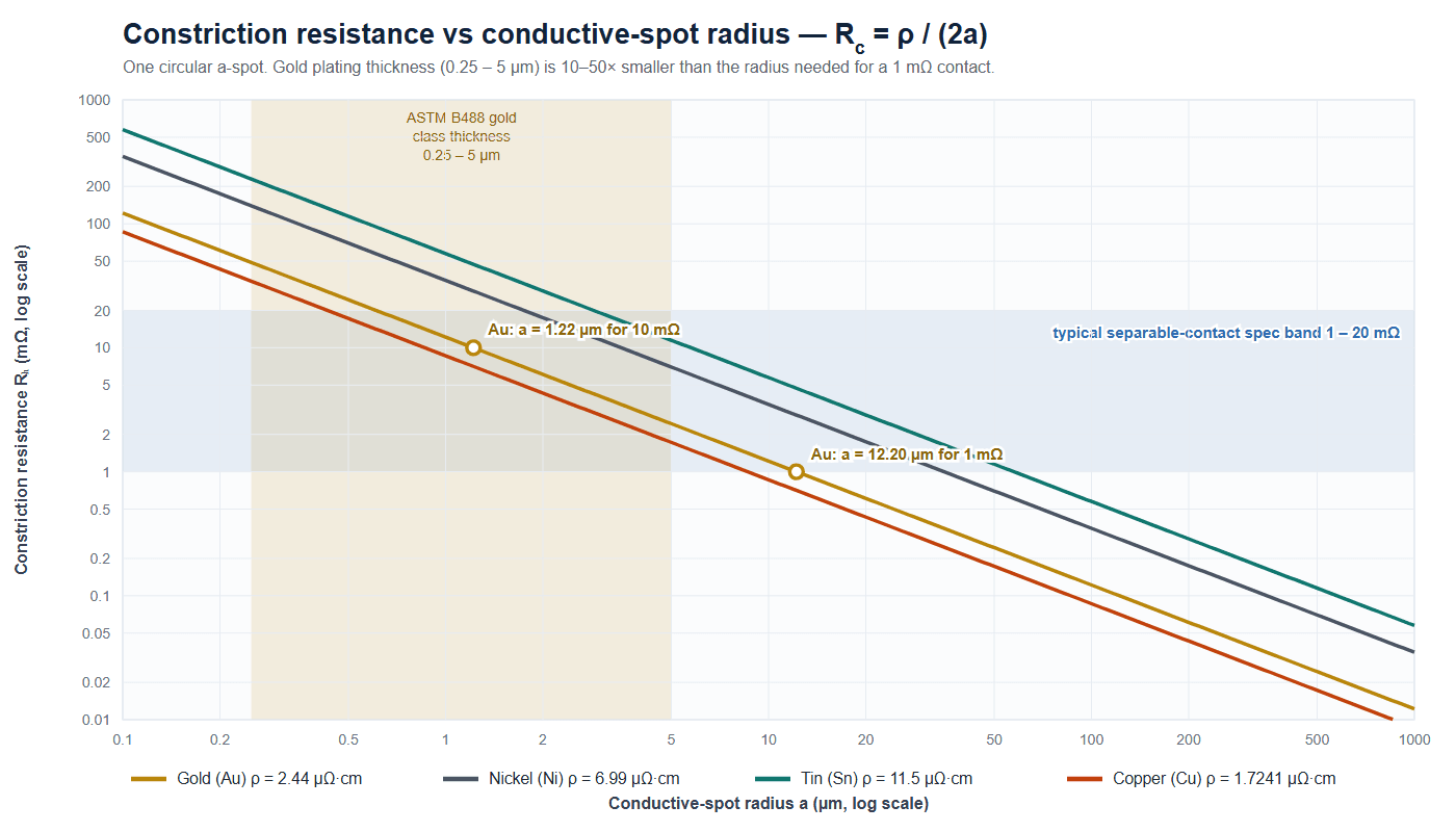
Two machined surfaces never touch across their apparent area, only at a scatter of microscopic high points through which current is squeezed. Holm’s result for a single circular conducting spot of radius a gives the constriction resistance:
R_c = ρ / (2a)
Here ρ is the resistivity of the material the current spreads into and a is the radius of the conducting spot. Two consequences follow. R_c is inversely proportional to a, so enlarging the spot or adding spots lowers resistance; nothing here mentions plating thickness. And ρ belongs to whichever material the spreading current actually flows through — current crosses a gold film in tenths of a micrometer, then spreads into the nickel underplate and copper alloy below. Once the spot radius exceeds the film thickness, the constriction happens in the substrate.
Solving the same equation for the spot radius turns it into a design check. Table 1 uses tabulated 20 °C resistivities: Cu 1.7241, Au 2.44, Ni 6.99, Sn 11.5 µΩ·cm.
| Target Rc | Copper base (µm) | Gold film (µm) | Nickel underplate (µm) | Tin film (µm) |
|---|---|---|---|---|
| 0.5 mΩ | 17.2 | 24.4 | 69.9 | 115 |
| 1 mΩ | 8.6 | 12.2 | 35.0 | 57.5 |
| 2 mΩ | 4.3 | 6.1 | 17.5 | 28.8 |
| 5 mΩ | 1.7 | 2.4 | 7.0 | 11.5 |
| 10 mΩ | 0.86 | 1.22 | 3.50 | 5.75 |
| 20 mΩ | 0.43 | 0.61 | 1.75 | 2.88 |
Read the 1 mΩ row against the gold column. Reaching 1 mΩ through gold alone needs a spot 12.2 µm in radius, while every gold thickness class in the relevant standards sits between 0.25 µm and 5 µm. The spot you need is 2.5 to 50 times thicker than the film — there is not enough gold there to spread in.
Why the same finish measures ten times different
Two connectors with identical gold, underplate and thickness can measure 2 mΩ and 20 mΩ on the same bench. The metallurgy did not change; the number and width of the conducting spots did. Normal force flattens asperity tips until the real area can carry the load, and because tips deform plastically that area scales roughly with load divided by hardness. Double the force and you get more, wider spots — exactly what the equation rewards. A burr on a stamping or a beam that lost its spring shrinks a and produces a reading that looks like a bad plating lot.
What Plating Thickness Actually Buys You
Read as a wear budget, the thickness ladder stops being arbitrary. ASTM B488, the specification for electrodeposited gold for engineering uses, defines a purity type, a Knoop hardness code and a minimum thickness class: 0.25, 0.50, 0.75, 1.0, 1.25, 2.5 and 5.0 µm. The legacy MIL-G-45204 uses the same scheme with grades in inches.
| Class (min. thickness) | Approx. µinch | Hardness code | Where it is normally used |
|---|---|---|---|
| 0.25 µm | 10 | A to C | Flash gold. Solder protection and shelf life only; not a mating surface for repeated cycles. |
| 0.50 µm | 20 | A to C | Low-cycle signal contacts, press-fit and one-time mating. |
| 0.75 µm | 30 | B to D | General signal and data contacts with moderate mating cycles. |
| 1.0 µm | 40 | B to D | Industrial signal contacts, hand-mated field devices. |
| 1.25 µm | 50 | B to D | The usual high-cycle industrial and telecom mating surface. |
| 2.5 µm | 100 | B to D | Severe abrasion or high cycle counts, including contacts cleaned and re-mated. |
| 5.0 µm | 200 | B to D | Extreme wear duty. Cost and process control become the limiting factors. |
Hardness is not implied by purity, and that decides many gold vs tin contact plating arguments. Type III is the highest purity at 99.9 % and is available only at code A, the softest, while Type II at 99.0 % reaches codes C and D — so “gold, 99.9 % pure, 1.25 µm” specifies a soft, easily galled mating surface. The class is a minimum, not a nominal.
The nickel underplate is doing more work than the gold
ASTM B488 requires a nickel underplate beneath gold on copper alloy substrates in most thickness classes, and its purposes explain most field failures: it blocks zinc diffusion from brass, levels the surface, stops pore corrosion, and carries the normal force so a thin film survives. Which type and code combinations are realistic to buy is set out by the NRAO Central Development Laboratory.
Nickel is not free: at 6.99 µΩ·cm its resistivity is about three times gold’s, so a given target needs a nickel spot nearly three times the radius of a gold one. In a published study of multilayer plated contacts, static resistance for tin layers 0.1 µm to 10 µm thick fell in the 0.8 mΩ to 2 mΩ range at 250 gf, and a 2 µm nickel underlayer left bright tin unchanged but pushed resistance up on matte tin. In gold vs tin contact plating the underplate is a reliability device, not a conductivity device — and a gold film is not hermetic, so “gold plated” without a thickness callout is not a specification.
Fretting Corrosion: The Failure Mode That Kills Tin
Fretting corrosion is the dominant field failure of tin-plated separable contacts, and it needs no mating event. Two mated contacts in a cabinet swinging between day and night temperatures move relative to each other by micrometers, because contact materials and housings expand at different rates. Each cycle abrades tin, exposes fresh metal, and that metal oxidizes within minutes.
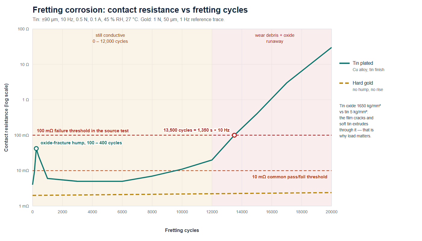
In a study of tin-plated copper alloy contacts at ±90 µm amplitude, 10 Hz, 0.5 N load, 0.1 A current, 45 % relative humidity and 27 °C, the resistance trace has a distinctive shape — and it is why gold vs tin contact plating decisions often come down to micromotion rather than current.
| Stage | Cycles | What is happening | Resistance trend |
|---|---|---|---|
| Oxide fracture | 100 to 400 | The brittle surface oxide cracks and soft tin extrudes through the cracks, creating fresh metal-to-metal contact. | Brief hump, then recovery |
| Stable plateau | 400 to 8,000 | Tin is ductile and conductive; the oxide is repeatedly broken by the micromotion. | Low and flat |
| Debris accumulation | 8,000 to 12,000 | Oxidized tin wear particles accumulate faster than they are expelled. | Slow but steady rise |
| Runaway | Beyond 12,000 | Conduction happens through an ever smaller set of metallic bridges until the contact is effectively an insulator. | Rise by orders of magnitude |
The same work reports the time to reach a 100 mΩ threshold at several temperatures. At 27 °C that is 1,350 s — at the 10 Hz test frequency, 13,500 cycles, exactly the knee where the trace turns upward. Two figures describing one failure from two directions is a useful sanity check: convert time-based numbers to cycles before quoting a fretting life.
| Temperature (°C) | Time to 100 mΩ (s) | Cycles at 10 Hz | Observation |
|---|---|---|---|
| 27 | 1,350 | 13,500 | Reference condition |
| 85 | 1,850 | 18,500 | Longer life than at 27 °C |
| 105 | 880 | 8,800 | Trend reverses |
| 125 | 810 | 8,100 | Accelerating |
| 155 | 680 | 6,800 | Accelerating |
| 185 | 580 | 5,800 | Roughly half the 27 °C life |
That table is not monotonic: at 85 °C the contact outlasted the 27 °C condition, and only above 105 °C does the trend settle into acceleration. Oxidation speeds up with temperature, but the tin also softens and debris is expelled instead of packing in, so no single Arrhenius factor carries a fretting life between temperatures.
Thick tin is a trap. Static resistance falls as tin gets thicker, but fretting life does not follow: in tests at 250 gf and 50 µm amplitude, cycles to 10 mΩ for 0.5 µm to 2.5 µm tin spread from roughly zero to 4,000 depending on bath, thickness and nickel underlayer, and work comparing 1 µm with 5 µm tin found the thicker layer produced more oxide and debris.
Tin Whiskers, Galling, and Wipe: Three Failure Modes the Catalog Omits
Tin whiskers
Tin finishes can grow conductive single-crystal filaments over months and years; in fine-pitch or high-voltage parts a whisker bridging two contacts is a permanent short. Risk comes from bath chemistry and deposit stress, not current. Bright tin is higher risk than matte, and the responses are a nickel underlayer, a controlled anneal, and no pure bright tin on fine-pitch parts. Cite JEDEC JESD201A when a customer asks, and see the NASA Goddard tin whisker resource for the mechanisms. Ask your plater for the anneal for their bath; it is not transferable. The tin specification is ASTM B545.
Gold on gold can cold weld
Gold’s counterintuitive failure is cold welding: two clean gold surfaces pressed together can adhere, because gold is soft and forms no protective oxide. Under micromotion that adhesive wear, called galling, tears material from the softer surface — hence hardness codes, with soft high-purity gold the most prone and hard gold at codes C and D the most resistant. Fretting tests agree: gold showed no resistance peak while reflow tin peaked near 140 mΩ within tens of cycles. Never use gold on a high-force power contact that slides during mating.
Tin needs wipe and load to work at all
Tin is not conductive until you break its oxide: tin oxide is around 1,650 kg/mm² hard, tin itself around 5 kg/mm². Under a 0.5 N load from a 1.5 mm radius rider the oxide shell cracks and soft tin extrudes through to form fresh metal contact. That is why gold vs tin contact plating changes connector geometry — tin needs a longer wipe stroke, because the wipe is an oxide-fracturing operation. Hold normal force high enough to extrude tin through the film: a low-force tin contact in a low-current circuit is the worst combination.
Durability and the Cost Model: Turning Thickness into Money
Durability is where the thickness budget is spent, and the standards split the measurement in two. IEC 60512-9-1 defines endurance test 9a, mechanical operation — it cycles the connector without electrical load and answers only whether the mechanism survives. Resistance is measured separately: IEC 60512-2-1 defines the millivolt-level method across a mated pair, and IEC 60512-2-2 the method at a specified test current.
Converting thickness into cycles is a division problem whose divisor only the supplier has: wear per cycle depends on normal force, wipe length, hardness, finish and whether debris escapes. Require measured wear depth per cycle, or cycles-to-10 mΩ from qualification, then check that thickness divided by wear rate leaves margin beyond the specified count. Two rules stretch the budget: put wear on the gold and wiping on the tin, and keep micromotion out of the interface. In a vibrating application the locking mechanism selection decision is a plating life decision.
Gold cost is mass: thickness times plated area times density, at 19.3 g/cm³ and 31.1035 g per troy ounce. Spot gold on 2026-09-17 was quoted at 4,270 to 4,320 USD per troy ounce; use the price on your quote date. Table 5 assumes 20 mm² of plated surface per contact, an M12-style contact band; scale linearly for your own area.
| ASTM B488 class | Thickness | Approx. µinch | Gold mass per contact | Gold metal cost per contact |
|---|---|---|---|---|
| Class 0.25 | 0.25 µm | 10 | 0.097 mg | 0.013 USD |
| Class 0.50 | 0.50 µm | 20 | 0.193 mg | 0.027 USD |
| Class 0.75 | 0.75 µm | 30 | 0.290 mg | 0.040 USD |
| Class 1.0 | 1.0 µm | 40 | 0.386 mg | 0.053 USD |
| Class 1.25 | 1.25 µm | 50 | 0.483 mg | 0.066 USD |
| Class 2.5 | 2.5 µm | 100 | 0.965 mg | 0.133 USD |
| Class 5.0 | 5.0 µm | 200 | 1.930 mg | 0.266 USD |
Three conclusions come out of that table. For gold vs tin contact plating, cost scales linearly in thickness and area, so a 2.5 µm finish costs five times a 0.5 µm finish and thickness is the only large lever. Per-contact metal cost is small, per-connector cost is not: a 12-pin circular connector at Class 1.25 carries about 0.79 USD of gold. And tin’s advantage is not metal cost but process — no tight thickness control, no scrap recovery. Compare cost per reliable contact-year.
Decision Matrix, and How to Write Plating on a Drawing
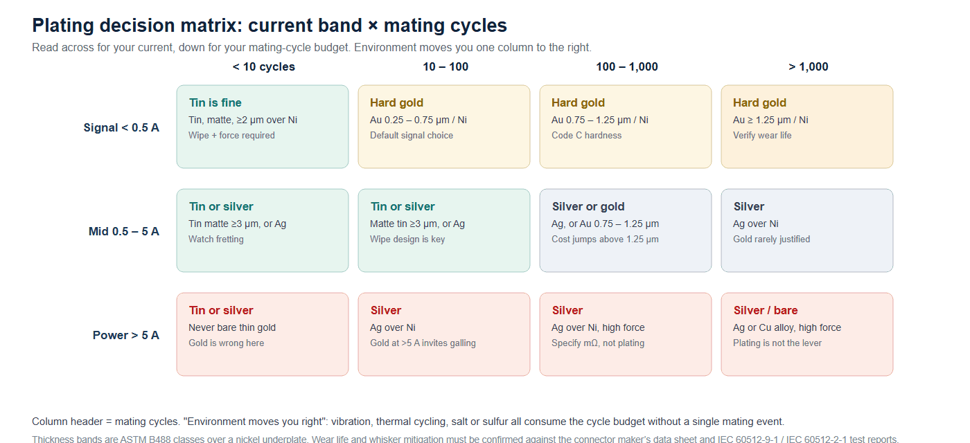
The whole argument collapses into one grid: read across for your current band and down for your mating-cycle budget, then move one column right if the environment adds vibration, thermal cycling, salt fog or sulfur, all of which consume cycle budget without a mating event.
| Current band | < 10 cycles | 10 to 100 | 100 to 1,000 | > 1,000 |
|---|---|---|---|---|
| Signal, under 0.5 A | Tin with wipe and force, or flash gold | Hard gold 0.25 to 0.75 µm over Ni | Hard gold 0.75 to 1.25 µm over Ni | Hard gold 1.25 µm and up over Ni |
| Mid, 0.5 to 5 A | Matte tin 3 µm and up, or silver | Matte tin 3 µm and up, or silver | Silver, or hard gold 0.75 to 1.25 µm | Silver over Ni |
| Power, over 5 A | Tin or silver; gold is the wrong answer | Silver over Ni | Silver over Ni with high force | Silver or bare copper alloy with high force |
Most plating disputes start because a drawing said “gold plated”. A complete callout has five elements, and any missing element will be resolved by whoever is cheapest, not whoever is right.
| Element | What to write | Why it matters |
|---|---|---|
| Finish identity | Gold per ASTM B488, Type II, Code C, Class 1.25, over nickel underplate | Fixes purity, hardness and minimum thickness in one line, in a scheme that carries across to the legacy MIL callout. |
| Underplate | Nickel underplate, minimum thickness, per ASTM B488 6.5.1 | The underplate carries load force and blocks diffusion. Without a minimum, thickness becomes whatever the plater ran last. |
| Coverage zone | Gold on the contact area, tin on the solder cup or crimp barrel, with masking boundaries stated | Solderability and mating performance have opposite requirements. Plating the whole part one way compromises one. |
| Resistance criterion | Contact resistance, millivolt level method, maximum value, after the stated number of cycles | Names the method from IEC 60512-2-1 and fixes the pass value instead of leaving it to the test house. |
| Durability and environment | Mating cycles, mechanical operation test per IEC 60512-9-1, plus the environmental sequence and its duration | Makes the thickness choice auditable. A duty claim without a cycle count and a test standard is not a requirement. |
For tin parts, add two things: the whisker mitigation, and the wipe length and minimum normal force on the assembly drawing rather than on the contact stamping. On an 8-way modular interface, dimensions come from IEC 60603-7, so a finish callout on an RJ45 plug must be read alongside it.
Two situations produce most plating failures at incoming inspection. The first is a low-normal-force resistance problem answered with thicker or softer gold — thickness does not enter the equation, so fix the spring or housing first. The second is a tin contact in a low-current, low-force, high-dwell application, where the oxide needs load or current to break and the design supplies neither; moving to gold, even flash gold over nickel, is the correct cheap answer. For mixed duty, selective plating — gold on the contact zone, tin on the solder or crimp zone, boundary on the drawing — costs more in process control and less in metal.
FAQ: Gold vs Tin Contact Plating in Practice
Does thicker gold lower contact resistance?
No. Constriction resistance is set by the size and number of conducting spots and by the resistivity of what the current spreads into. A 0.25 µm gold film is far thinner than the spot radius any normal target requires, so current spreads in the nickel underplate and copper body. Thicker gold buys wear life, not milliohms.
At what current is gold no longer worth it?
There is no sharp line, but the decision flips in the single-digit amp range. Below about 0.5 A the contact cannot clean itself electrically and gold’s oxide-free surface does real work. Above roughly 5 A, contact force and cross-section dominate, the finish becomes a wear surface rather than a conduction path, and silver or matte tin is cheaper and better.
Why does gold vs tin contact plating change the wipe stroke?
Because tin is never clean. Tin oxide has a hardness around 1,650 kg/mm² against roughly 5 kg/mm² for the tin beneath it, so the wipe has to fracture that brittle shell across the whole contact zone before soft tin extrudes through the cracks and makes real metal contact. Gold has no such film, so a shorter wipe is sufficient.
How many fretting cycles can a tin contact survive?
In published testing on tin-plated copper alloy at ±90 µm, 10 Hz, 0.5 N and 0.1 A, resistance stays low to about 8,000 cycles, rises to 12,000, then climbs rapidly to a 100 mΩ threshold near 13,500 cycles. That is one test matrix, not a constant — test at your own conditions.
Is bright tin or matte tin better?
Matte tin carries lower whisker risk and is widely used on separable contacts, but it is softer and makes more debris under fretting. Bright tin is harder and wears better in some tests, with higher whisker risk. Pick by dominant failure mode — fretting wear or whisker shorting — and specify the mitigation, not the bath name.
Can I mate a gold contact to a tin contact?
It happens constantly and it works, but it has to be designed. The tin side still needs wipe and load to fracture its oxide, and the gold side is the harder surface doing the abrading. Specify wipe and force for the tin half, and expect it to set the durability number.
What should I put on the drawing if I do not know the thickness I need?
Write the mechanism you are buying, not a guess: cycle count, current, wipe length, minimum normal force and environment, and require the supplier to propose a finish with the test data behind it. Then require the callout in ASTM B488 terms including the underplate, plus the resistance limit and durability test.
Does the nickel underplate ever hurt?
It raises resistance slightly: nickel is about 6.99 µΩ·cm against 2.44 for gold and 1.7241 for copper, so a given target needs a wider spot when spreading happens in nickel. Measured work found a 2 µm underlayer left bright tin unchanged but raised matte tin. Specify a minimum, and do not add nickel for lower milliohms.
Get a plating callout you can audit
Send the current, cycle count, wipe length and environment, and HKWIRE will return the finish type, ASTM B488 thickness class, nickel underplate minimum, selective plating boundaries, and the resistance and durability tests to write on the drawing. Material declarations for RoHS and REACH are provided per project.
Sources: ASTM B488, ASTM B545, IEC 60512-2-1, -2-2 and -9-1, IEC 60603-7, JEDEC JESD201A, the NASA Goddard tin whisker resource, NRAO Technical Note 229, Ossart et al. (WIT Transactions on Engineering Sciences Vol. 55), Park, Sankara Narayanan and Lee (Tribology International). Resistivities are 20 °C tabulated values.
Related: DC power cable and barrel plug selection, RJ45 vs M12 X-coded Ethernet, fieldbus cable selection, single pair vs four pair Ethernet, USB-C versions and PD, IP67 vs IP68 vs IP69K, bend radius and pull force, overmolded cable design, specifying an overmolded assembly, harness drawing checklist, cable assembly RFQ.
Products: M12 K-coded power, M12 S-coded power, M12 CAN bus, M12 washdown, M12 X-code Cat6A, M12 D-code, M12 bulkhead, IP67 RJ45 coupler, SPE bulkhead, Cat5e patch cord, Cat8 patch cord, ix Industrial patch, encoder cable, hybrid servo, XT60 DC plug, pogo pin, plus the Ethernet patch cord, panel mount, signal and data and M8 and M12 circular ranges, with the M12 coding guide.







