

Most cable failures that come back from the field are mechanical, and almost all of them trace back to one of three numbers that were never calculated: the cable bend radius, the pulling tension, and the support interval. Electrical selection gets all the attention; these three decide whether the assembly is still working next year. This guide gives you the multipliers, the formulas and the inspection points, with the arithmetic worked out so the numbers can go straight onto a drawing.
Two of the three have a rule behind them that can be quoted and checked. The third — the radius you allow a continuously flexing cable — has no standard at all, only the curves a cable maker publishes from its own test rig, and any article that gives you a single multiple for it is guessing. HKWIRE builds assemblies to IPC/WHMA-A-620, so the routing limits below are the ones that end up in our process instructions as well as on customer drawings.
1. Cable bend radius: the single most common cause of premature failure
A cable bend radius is quoted as a multiple of the cable outside diameter (OD), and the multiplier depends entirely on what the cable does in service. That part is well known. What is less well known is that the multipliers circulating online have three different kinds of provenance — a standard clause, a manufacturer’s data sheet, and folklore — and they get quoted as if they were interchangeable.
| Service condition | The figure that circulates | Where it actually comes from | What to put on the drawing |
|---|---|---|---|
| Fixed installation, one-time forming | about 4 × OD | manufacturer’s data sheet for the construction | the maker’s fixed-installation radius |
| 4-pair balanced twisted pair, unloaded or loaded | 4 × OD | TIA-568-C.0, clause 5.3.2.1, which gives 4 × OD in both states | 4 × OD |
| Occasional flex, installation handling | about 8 × OD | no single standard; screened and armored constructions and individual makers publish higher values | the maker’s value for that construction |
| Continuous flex in a drag chain | 10 to 15 × OD | nothing. It is a repeated claim with no standard behind it | the maker’s chain curve. igus publishes CF9 control cable at 5 to 8.5 × d |
| Torsional (twist) service | 15 to 20 × OD | the torsion specification, which is not a radius at all | the twist rating in degrees per meter. igus publishes CF77.UL.D at plus or minus 30 to plus or minus 180 °/m |
The rows with the weakest provenance are the ones that cause arguments, because a maker’s figure and a standard clause look identical once someone copies them into a drawing note.
Two corrections are worth making explicitly, because both are widespread. First, the rule that unshielded twisted pair needs 8 × OD during installation and 4 × OD afterwards is a myth: TIA-568-C.0 clause 5.3.2.1 gives 4 × OD, and the 8 × figure belongs to screened and other constructions where an individual maker chooses it. Second, NEC 300.34 — the clause that gives 8 × the outside diameter for unshielded conductors and 12 × for shielded or lead-covered ones, quoted verbatim in this Rockwell Automation paper on conductor bending — sits in Part II of Article 300, which covers installations over 1000 V. Quoting it as the general low-voltage building rule is a common mix-up, and the reader who knows the code will spot it immediately.
Continuous flex is the other place where the circulating figure should be replaced. The igus chainflex range for CF9 control cable is published at 5 to 8.5 × d, backed by the chainflex guarantee terms of four years or ten million double strokes, and that is a test result from a specific construction rather than a rule anyone can generalize.
Optical fiber has its own numbers and they are not multiples of the diameter in every case. TIA-568.3-D gives a cable with four or fewer fibers a static radius of 25 mm and a loaded radius of 50 mm at 220 N of tension, while other indoor fiber cables are given as 10 × OD static and 20 × OD loaded. If a route carries fiber and copper together, the fiber number usually governs the pull point geometry.
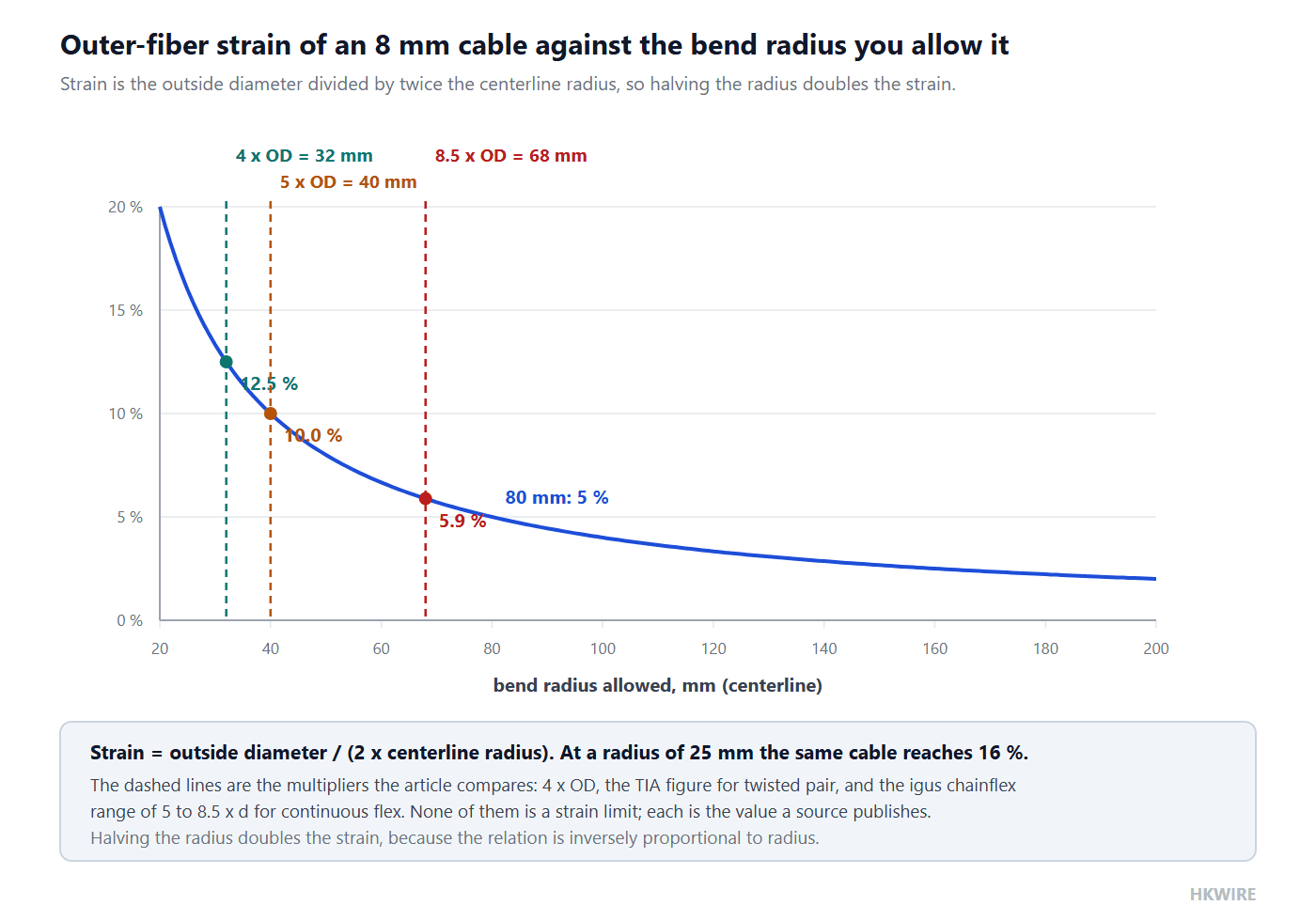
The geometry behind the multiplier: strain = d / (2R)
The reason a radius matters at all is that bending stretches the outside of the cable. Take the neutral axis at the centerline: at a bend angle θ, the centerline arc has length Rθ while the outer fiber has (R + d/2)θ. The difference over the original length gives
ε = d / (2R)
where d is the outside diameter and R is the centerline bend radius. This is the standard flexure relation from any mechanics of materials text, and it has one consequence worth internalizing: strain is inversely proportional to radius, so halving the radius doubles the strain, and the relationship is smooth rather than a cliff. An 8 mm cable at an 80 mm radius sits at 8 / 160 = 5 % outer-fiber strain. The same cable at a 25 mm radius sits at 8 / 50 = 16 %. Nothing about the cable changed except the radius that was allowed.
Putting the published multipliers onto the same axis makes the spread visible. At 4 × OD the radius is 32 mm and the strain is 8 / 64 = 12.5 %. At the igus chainflex range of 5 to 8.5 × d the radius is 40 to 68 mm, which is 10 % down to 5.9 %. A drag-chain cable quoted at 10 × OD would sit at 6.25 %, and one at 15 × OD at 3.3 %.
Worked example
An 8 mm OD cable in a drag chain, with the radius taken from the maker’s curve rather than from a rule of thumb. At 5 × d the minimum radius is 40 mm; at 8.5 × d it is 68 mm.
- If the carrier geometry only allows a 25 mm radius, the cable is being bent at 16 % outer-fiber strain instead of the 5.9 % it was designed for. That is not a small overshoot: it is roughly 2.7 times the strain, applied every cycle.
- The two ends of the chain — the fixed point and the moving point — are where the tightest radius in the whole system occurs, and they are also where the connector sits. The chain itself is usually the easy part.
2. Pulling tension during installation
Installers break cables by pulling them through conduit or trays, and the limit is set by the conductor, not by the jacket. The rule that has an actual traceable source is expressed per unit of conductor cross-section:
T_max = σ_allow × A_Cu
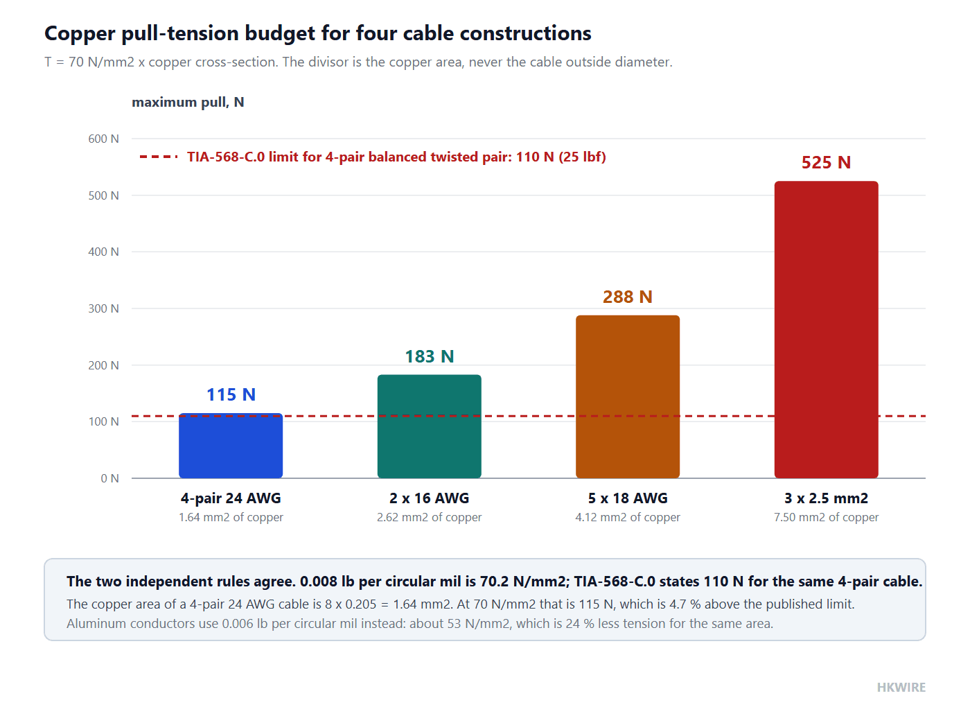
with σ_allow = 0.008 lb per circular mil for copper and 0.006 lb per circular mil for aluminum, a figure that traces back to AEIC G5-90 and IEEE 1185 and appears in cable makers’ installation guides such as this Southwire installation and application guide for 600 V conductors. Converting it is worth doing once: one circular mil is 5.067 × 10⁻⁴ mm², and 0.008 lb is 0.0356 N, so the allowance works out to about 70 N/mm² of copper. Aluminum gets about 53 N/mm².
The critical detail is what A_Cu is. It is the copper cross-section that carries the pull, not the overall area of the cable, and not the outside diameter. A thin, many-conductor data cable therefore has a surprisingly small tension budget, while a coarse power cable has a large one. This is the opposite of the intuition people bring from rope, where thickness is strength.
| Construction | Copper cross-section | Maximum pull at 70 N/mm² |
|---|---|---|
| 4-pair 24 AWG | 8 × 0.205 = 1.64 mm² | 115 N |
| 2 × 16 AWG | 2 × 1.31 = 2.62 mm² | 183 N |
| 5 × 18 AWG | 5 × 0.823 = 4.12 mm² | 288 N |
| 3 × 2.5 mm² power cable | 3 × 2.50 = 7.50 mm² | 525 N |
Here is the cross-check that makes the rule trustworthy, and it is the reason this is worth reading rather than skimming. A 4-pair 24 AWG cable contains eight conductors of 0.205 mm², so 1.64 mm² of copper. At 70 N/mm² that is 115 N. TIA-568-C.0 gives a maximum pulling tension of 110 N (25 lbf) for exactly this cable. Two independent sources — a conductor-strength rule from the power cable world and a cabling standard from the data world — land within about 5 % of each other. That agreement is the real answer to “where does the pulling limit come from”.
Running the arithmetic backwards is just as useful on site. If the route and the pulling gear only give you a 100 N budget, the copper area you may pull is 100 / 70 = 1.43 mm² — which is less than the 1.64 mm² of a single 4-pair 24 AWG data cable. A short run of network cable on a tight bend already exceeds that budget, which is why the practical answer is a pulling grip that engages the jacket and any strength members, never a pull on the conductors alone.
| Tension budget available | Copper area allowed | What that covers |
|---|---|---|
| 100 N | 1.43 mm² | less than one 4-pair 24 AWG cable at 1.64 mm² |
| 288 N | 4.12 mm² | a 5 × 18 AWG multicore, and no more |
| 525 N | 7.50 mm² | a 3 × 2.5 mm² power cable |
That is a light pull in absolute terms, which is why installers who judge by feel get it wrong. If a run needs more force than the limit allows, the correct answer is a different route or intermediate pull points, not more force. The cable will often survive the pull and fail months later, because the damage is work-hardening and strand breakage inside the conductor rather than a visible tear.
3. Termination pull-out and strain relief
Separate from installation pull, the termination has to hold the cable in service for years. This is a retention specification and it belongs on the drawing, not in a conversation:
- Pull-out force — the force the connector or boot withstands before the cable moves in the body. Specify a number rather than leaving the field undefined, and ask the maker what the sample achieved rather than what the mold can theoretically take.
- Where the splice sits — any conductor splice or crimp must be inside the strain-relieved zone, never in the bending region. A splice in a flexing zone is a fatigue crack with a schedule.
- Boot geometry — a molded boot that tapers gently spreads the bend over its length instead of concentrating it at one line. The radius at the end of the boot is the number to control.
For motion and vibration, this is precisely why overmolding outperforms field-wireable connectors — see how to specify an overmolded assembly. The retention figure and the bend transition are two different requirements with two different tests, and a specification that names only one of them is half a specification. The bend transition is where the cable bend radius collapses to whatever the boot happens to allow, so it is the number worth measuring on the first article.
Reading a retention figure
Retention values are only comparable when the specimen and the pull rate are stated. A figure taken on a short molded sample pulled slowly is not the same as one taken on a finished assembly pulled quickly, and neither is the same as the sustained load of a vertical run. HKWIRE states the specimen and the pull rate alongside the retention figure for that reason, and it is the first thing worth asking any supplier for.
4. Support intervals and vertical runs
Gravity is a long-term load rather than a short one, and cables left unsupported sag until the stress concentrates at the top clamp. The spacing figures come from several different documents with different scopes, which is where most of the confusion starts.
| Source | What it governs | The figure |
|---|---|---|
| NEC Table 300.19(A) | maximum support interval, indexed by conductor size | copper 18–8 AWG: 100 ft (30.5 m); 6 AWG–1/0 AWG: 100 ft; 2/0–4/0 AWG: 80 ft (24.4 m); above 750 kcmil: 35 ft (10.7 m) |
| HD 60364-5-52, Table 2 | cable support spacing for fixed installations | horizontal 250–400 mm and vertical 400–550 mm, in bands by overall diameter; for NYY and NYCWY, horizontal 20 × D and not more than 800 mm, vertical not more than 1.5 m |
| NEMA VE 1 | cable tray load classes | spans start at 5 ft (1.5 m); load classes are A = 50, B = 75 and C = 100 lb/ft with a safety factor of 1.5 |
Note the two attributions carefully. The support-spacing table lives in the harmonized European document HD 60364-5-52, not in the IEC 60364-5-52 text, and 1.5 m in NEMA VE 1 is the bottom of the tray span range rather than a required support interval.
The intervals tighten as the conductor gets heavier, which is the visible signature of a weight criterion: 100 ft for 8 AWG but 35 ft above 750 kcmil. That is a useful way to sanity-check any spacing rule you are given — if it does not change with conductor size, it is probably about something other than weight. It is also the point where the cable bend radius and the support interval meet: a clamp that is too tight deforms the cable, and a clamp spaced too far apart lets the cable sag into a radius you never designed.
The vertical run calculation
For a vertical run, the load at the top clamp is simply the weight of everything below it. Take an 8.0 mm cable with a jacket annulus from 5.5 mm to 8.0 mm at 1.42 g/cm³: the annulus is 26.51 mm², which is 37.6 g per meter of compound. Add the 4.12 mm² of copper at 8.96 g/cm³ for another 36.9 g per meter, and the cable weighs about 74.5 g per meter, or 0.73 N per meter. Fillers and tapes are ignored, so treat that as a floor.
| Unsupported length | Cable mass | Load carried by the top clamp |
|---|---|---|
| 10 m | 0.75 kg | 7.3 N |
| 20 m | 1.49 kg | 14.6 N |
| 30 m | 2.24 kg | 22 N |
| 50 m | 3.73 kg | 37 N |
| 100 m | 7.45 kg | 73 N |
| 300 m | 22.4 kg | 219 N |
Read that table against the tension budget from section 2 and the conclusion is counterintuitive but solid. This cable’s conductor budget is 288 N, which it would only reach at about 395 m of unsupported vertical run. Self-weight is therefore not what breaks the conductor over any realistic riser length. What self-weight does break is the termination, whose retention is specified an order of magnitude lower, and the jacket at the clamp, which creeps and necks under a sustained load that would be harmless as a short-term pull. The design rule is to divide the maker’s stated retention force by 0.73 N/m to get the maximum unsupported length, and to clamp at intervals below that.
5. Segregation and routing for signal integrity
Physical routing is also an EMC decision, and the mechanical rules above do not override it:
- Keep power and signal cables physically separated, in separate trays or behind a divider, and cross at right angles where they must cross at all.
- Keep the common-mode path short: shield the signal pair and bond the shield at one end, or per the system grounding scheme, rather than leaving it floating.
- In a drag chain, lay power and signal in separate compartments where the carrier provides them. The mechanical bundle you have already designed is also the electromagnetic one.
6. Inspection points that catch the failures early
- The end terminations of a drag chain — the tightest radius in the system. Look for jacket crazing and boot cracking at the point where the cable leaves the boot.
- The top clamp of a vertical run — look for necking of the jacket under its own weight, which appears as a visible waist just below the clamp.
- The entry to a conduit — look for a cut or a chafed jacket at the bell mouth. A radius former or a proper bell mouth is cheaper than the rework.
- Conductor fatigue — intermittent faults that appear only when the cable is bent are the classic symptom, and a continuity test on a straight cable will not reveal them.
7. Sidewall pressure: the tension limit no code sets
The tension budget from section 2 says what the copper can take. It says nothing about what happens where that tension is fed around a bend, and that is a second limit with its own name. Sidewall pressure is the radial force the conductor bundle presses onto the insulation at the inside of a bend:
SP = T / R
with the tension in newtons and the radius in meters, giving an answer in newtons per meter. For a three-core cable laid up in a triangle the geometry adds a factor, which is why makers publish a coefficient with their tables. There is no NEC clause for sidewall pressure at all; the values come from IEEE and ICEA practice and from individual cable makers, so the figure you design to is the one your maker publishes. Note that this limit and the cable bend radius are two views of the same geometry: the radius appears in the denominator of both, so tightening it costs you twice.
| Case | Tension | Radius | Sidewall pressure |
|---|---|---|---|
| 5 × 18 AWG, pulled on a tray bend | 288 N | 0.25 m | 1,152 N/m (1.15 kN/m) |
| 3 × 2.5 mm² power cable, generous bend | 525 N | 0.20 m | 2,625 N/m (2.6 kN/m) |
| 3 × 2.5 mm² power cable, tight bend | 525 N | 0.10 m | 5,250 N/m (5.3 kN/m) |
Compare those with the reference values that North American cable makers publish, for example in the Southwire MC cable installation guide: roughly 300 lb/ft, or 4.4 kN/m, for tray-type MC cable, and around 1000 lb/ft, or 14.6 kN/m, for power cable. The third row lands above the first of those references, and nothing about the cable changed except the bend radius. That is the practical point of computing sidewall pressure: it explains why a pull that is well inside the tension budget can still damage a cable, and why the person who quotes the low tension figure and then bends the cable around a 100 mm former has satisfied one limit and broken another.
8. Seven things a general guide will not tell you about cable bend radius
- The two published rules cross-validate. 0.008 lb per circular mil works out to about 70 N/mm²; applied to the 1.64 mm² of a 4-pair 24 AWG cable it gives 115 N, against the 110 N that TIA-568-C.0 states. That agreement is the real origin of the pulling limit, and it is never explained.
- The divisor is copper cross-section, not cable diameter. Thin multicore data cables have small tension budgets and coarse power cables have large ones, which is the reverse of the intuition brought from rope. Never pull a network cable the way you would pull a rope.
- NEC 300.34 is in the over-1000 V part of Article 300. Its 8 × and 12 × outside-diameter figures are not the general low-voltage building rule, and treating them as one is a frequent misattribution.
- TIA gives 4 × for unshielded twisted pair in both states. The familiar “8 × during installation, 4 × once fixed” is folklore; higher values appear in screened constructions and in individual makers’ data sheets.
- Vertical weight has to be calculated, not assumed. An 8 mm cable weighs about 0.73 N per meter here, so the conductor budget would only be reached at roughly 395 m. The binding constraint is the termination retention, and the unsupported length limit is that retention divided by 0.73 N/m.
- Filling the wrong table produces the wrong answer. There is no fixed fill percentage in IEC 60364-5-52; the percentage limits are in NEC Chapter 9 Table 1, and the support spacings are in HD 60364-5-52 and NEC Table 300.19(A).
- Continuous-flex radius is a curve, not a number. No standard publishes a multiple of the diameter for drag-chain service. The figure comes from the maker’s test rig, and igus publishes 5 to 8.5 × d for CF9 — well inside the 10 to 15 × OD that keeps being repeated.
How we help
Send us the route — bend radii, run lengths, support points — together with the motion profile and the environment, and we return a cable with the right conductor class, jacket and overmolded termination, plus the cable bend radius and retention values to put on your drawing. See our M8 and M12 motion cables for the standard build, or open a project through custom development.
Frequently asked questions
What cable bend radius should I use for continuous flex?
There is no standard multiple of the diameter for drag-chain service, so the number has to come from the maker’s chain curve. As a reference point, igus publishes CF9 control cable at 5 to 8.5 × d, which is tighter than the 10 to 15 × OD that circulates. At the chain ends, where the radius is always tightest, the end termination geometry governs.
How hard can I pull a cable during installation?
About 70 N per mm² of copper, which comes from the 0.008 lb per circular mil rule (aluminum is 0.006, about 53 N/mm²). For a 4-pair 24 AWG cable that is 115 N, against the 110 N limit TIA-568-C.0 states — the two rules agree. Always pull on a grip that engages the jacket, never on the conductors.
Why do cables fail at the connector?
Because the radius collapses to nearly zero at the termination, and the strain relation is inversely proportional to radius. A molded strain relief spreads that transition over a length of boot instead of concentrating it on one line, and keeping any splice out of the bending region removes a built-in fatigue crack.
Do vertical runs need special support?
Yes, but the reason is not conductor strength. An 8 mm cable here weighs 0.73 N per meter, so it would need roughly 395 m of unsupported run to reach its 288 N conductor budget. The real limit is the termination retention — divide that figure by 0.73 N/m for the maximum unsupported length — and the jacket necking under the clamp.
Is the minimum bending radius the same for fiber and copper?
No. TIA-568.3-D gives a cable of four fibers or fewer a 25 mm static radius and 50 mm loaded at 220 N, while other indoor fiber cables are quoted as 10 × OD static and 20 × OD loaded. Copper and fiber numbers come from different documents and should be shown separately on a route drawing.
What is sidewall pressure and do I have to check it?
It is the radial force the conductors press onto the insulation at a bend, computed as tension divided by radius in newtons per meter. NEC has no clause for it, so the value comes from IEEE, ICEA and individual makers — around 4.4 kN/m for tray-type MC cable and 14.6 kN/m for power cable in published reference tables. A pull that is inside the tension budget can still exceed the sidewall figure on a tight bend.
How often should a vertical run be clamped?
Work it out rather than copying a rule: divide the maker’s retention figure for the termination by the cable’s weight per meter. The support spacing tables (NEC Table 300.19(A) and HD 60364-5-52 Table 2) give the maximum intervals the installation standard allows, and the tighter of the two applies.
Does the conduit fill rule come from IEC 60364-5-52?
No. IEC 60364-5-52 does not set a fixed fill percentage; it uses current-carrying capacity correction factors for grouping. The percentage limits are in NEC Chapter 9 Table 1: 53 % for one conductor, 31 % for two, 40 % for three or more, and 60 % for a raceway 24 in or shorter.







