

A fieldbus cable looks like any other shielded twisted pair, and that is exactly what makes it dangerous to buy by appearance. Every industrial fieldbus is built around a specific characteristic impedance — 150 Ω for PROFIBUS DP, 120 Ω for DeviceNet, CANopen, CAN and RS-485, and 110 Ω for CC-Link — and the cable is the transmission line that carries those bits over distance. Install the wrong impedance and the network does not fail gracefully; a fifth of the signal reflects straight back into the transmitter and the link drops or errors out. This guide turns the choice of a fieldbus cable into arithmetic: the reflection coefficient that explains why impedance matters, the segment-length limits that are physical rather than advisory, and the termination and cable-parameter values that decide whether a network will run at all.
One note on scope before the detail. HKWIRE supplies the fieldbus cable and the assemblies that connect it, and we are certified to ISO 9001 with RoHS and REACH material declarations provided per project. The impedance, length and termination figures below come from the protocol specifications themselves, cited in each section, and where a value is a typical or approximate one it is labeled as such. A fieldbus cable choice is a matter of matching three numbers — impedance, length and termination — and every one of them is checkable.
1. What a fieldbus cable actually is
A fieldbus replaces the old point-to-point 4–20 mA loop with a single shared network over which many devices take turns talking. The physical layer of that network is a differential serial link, and the cable is the transmission line between the transceivers. That is the difference between a fieldbus cable and ordinary hook-up wire: at the bit rates and distances involved, the cable’s high-frequency behavior — its characteristic impedance — determines whether a clean edge arrives at the far end or a smeared, reflected mess arrives instead. A pair of loose wires in a conduit may carry the same voltage levels and still not work, because the impedance is uncontrolled.
The value that describes a transmission line’s behavior is its characteristic impedance, and for a lossless line it is set by the cable’s own geometry and materials:
Z₀ = √(L/C)
where L is the distributed inductance per unit length and C the distributed capacitance per unit length. The twist pitch, the conductor spacing, the insulation and the shield all move this number, which is why the impedance is a manufactured property, not a rating you can infer from a wire gauge. It is the input to the reflection formula that follows.
2. The reflection coefficient: why impedance is the identity of the cable
When a signal traveling down a line meets an impedance that differs from the line’s own, part of it reflects back toward the source. The fraction that reflects is the reflection coefficient:
Γ = (Z_L − Z₀) / (Z_L + Z₀)
where Z₀ is the characteristic impedance of the line and Z_L is the impedance it meets — a wrong cable, a missing terminator, or a badly placed stub. When Z_L = Z₀ the numerator is zero and nothing reflects; the larger the mismatch, the larger Γ. The sign records the direction of the reflection, but what matters for a data link is the magnitude — how much of the signal comes back to corrupt the next bit. This is the whole reason each bus has a mandated impedance, and the reason they cannot be swapped.
Γ is an amplitude (voltage) reflection coefficient, so a value of 0.2 means 20% of the signal amplitude reflects. The reflected power is Γ², so the same mismatch returns 4% of the power — but the 20% amplitude is what the receiver actually has to cope with, riding on top of the next transmitted bit. Both numbers describe the same physical event; do not let a supplier quote only the small power figure to make a mismatch sound harmless.3. Worked example: what a 100 Ω cable does to three buses
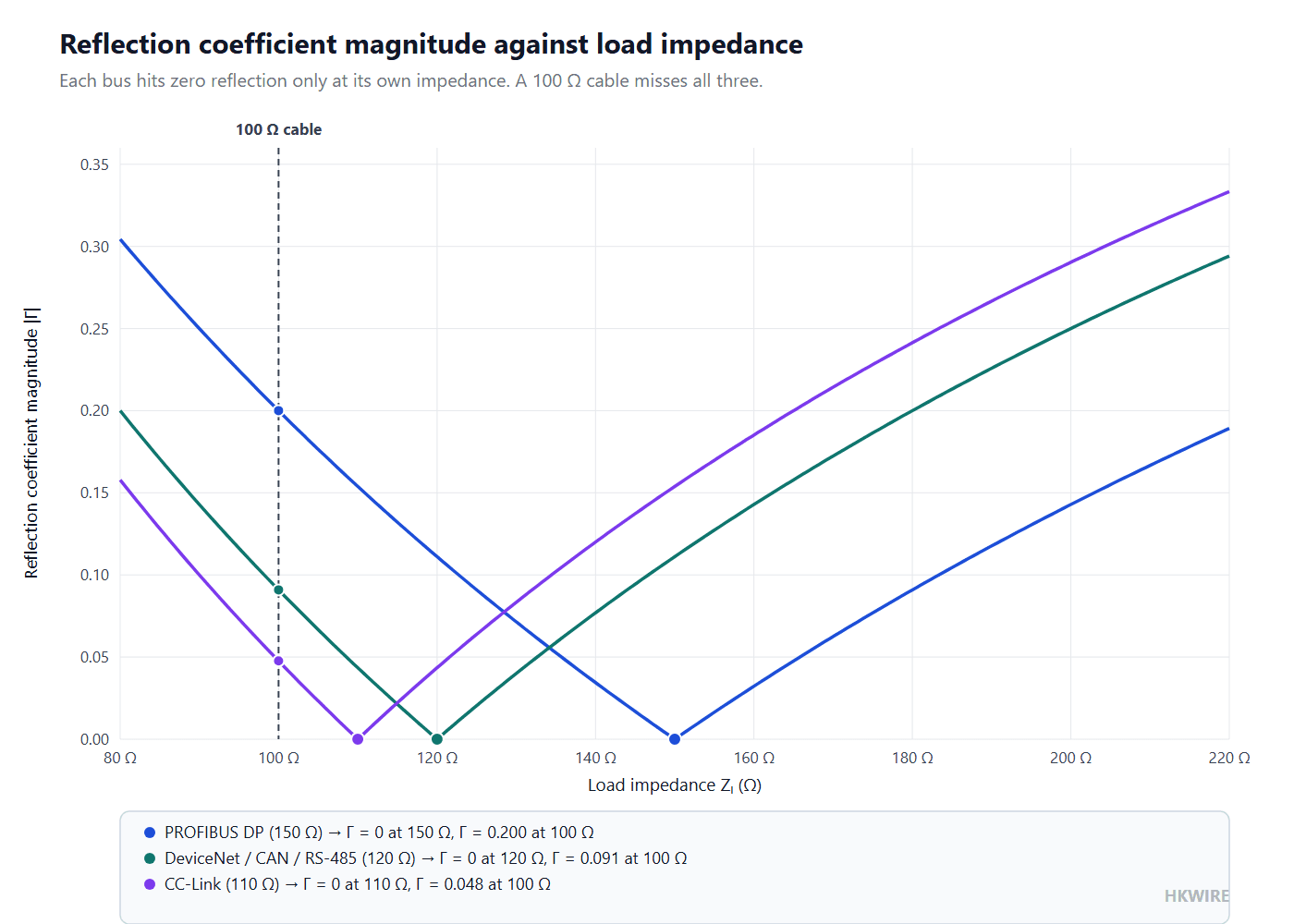
The most common mistake is installing a generic 100 Ω cable — the impedance people associate with ordinary twisted-pair and Ethernet-style wiring — onto a fieldbus that expects something else. Run the reflection arithmetic for each bus and the mistake becomes a number:
| Bus (system impedance) | Installed cable | Reflection coefficient | Signal reflected |
|---|---|---|---|
| PROFIBUS DP (150 Ω) | 100 Ω cable | (150 − 100) / (150 + 100) = 50 / 250 = 0.2 | 20% |
| DeviceNet / CAN / RS-485 (120 Ω) | 100 Ω cable | (120 − 100) / (120 + 100) = 20 / 220 = 0.091 | about 9% |
| Any bus, correctly matched | cable of the bus impedance | (Z₀ − Z₀) / (Z₀ + Z₀) = 0 | none |
The reflection coefficient is Γ = (Z_L − Z₀)/(Z_L + Z₀); the 20% and 9% figures are the amplitude reflected at a single impedance junction.
Read that table against the field experience. A 100 Ω cable on PROFIBUS reflects 20% of the signal at the junction, and at 12 Mbit/s a segment has almost no margin for that kind of corruption — the link either fails to come up or racks up retries and dropped slaves. The same 100 Ω cable on DeviceNet reflects only 9%, which is why some networks limp along with the wrong cable at low rates and then die as soon as the baud rate is raised. The correct match, Γ = 0, is not a nicety; it is the condition under which the protocol’s distance and node counts are actually valid.
4. The impedance of every major fieldbus, in one table
The impedance is the first number to get right, and each protocol pins it down in its own specification. Note that DeviceNet, CAN and RS-485 all land on 120 Ω, but that does not make their cables interchangeable — they differ in conductor count, shield requirements and the electrical parameters in the next section.
| Fieldbus | Characteristic impedance | Where the number comes from |
|---|---|---|
| PROFIBUS DP | 150 Ω (standard text 135–165 Ω, i.e. ±10%; 3–20 MHz) | PROFIBUS DP specification, Type A cable |
| DeviceNet | 120 Ω ±10% (at 1 MHz) | DeviceNet specification, data pair |
| CANopen / CAN | 120 Ω | ISO 11898 |
| RS-485 | 120 Ω | RS-485 physical layer practice |
| CC-Link | 110 Ω (±15 Ω / ±10 Ω) | CC-Link specification |
The PROFIBUS 150 Ω figure and the DeviceNet 120 Ω figure are the protocol’s own values; CC-Link is 110 Ω by the CC-Link specification.
The point of the table is that the impedance is not a family trait. PROFIBUS at 150 Ω, the 120 Ω group and CC-Link at 110 Ω are three different transmission lines, and a cable that is excellent for one is a mismatch for the other two. For a practical reference on the DeviceNet side, the Beijer Electronics DeviceNet guide walks through the cable and termination requirements, and the CC-Link specification publishes the 110 Ω figure directly. For the RS-485 reflection and termination reasoning, the Texas Instruments RS-485 design guide is the reference to keep open.
The 120 Ω group deserves one clarification, because it is where the wrong cable is most often justified. DeviceNet is a four-wire system — two conductors for the 24 V device power and two for the CAN data pair — so its cable is a shielded two-pair construction, not a single pair. CANopen and RS-485 typically run on a single shielded pair. All three terminate near 120 Ω, but a cable built for DeviceNet power-plus-data is not a CAN cable, and neither substitutes for the other where the shield, the pair count or the power-carrying capacity matters. Match the cable to the protocol, not just to the 120 Ω number.
5. Segment length versus baud rate is a physical limit, not advice
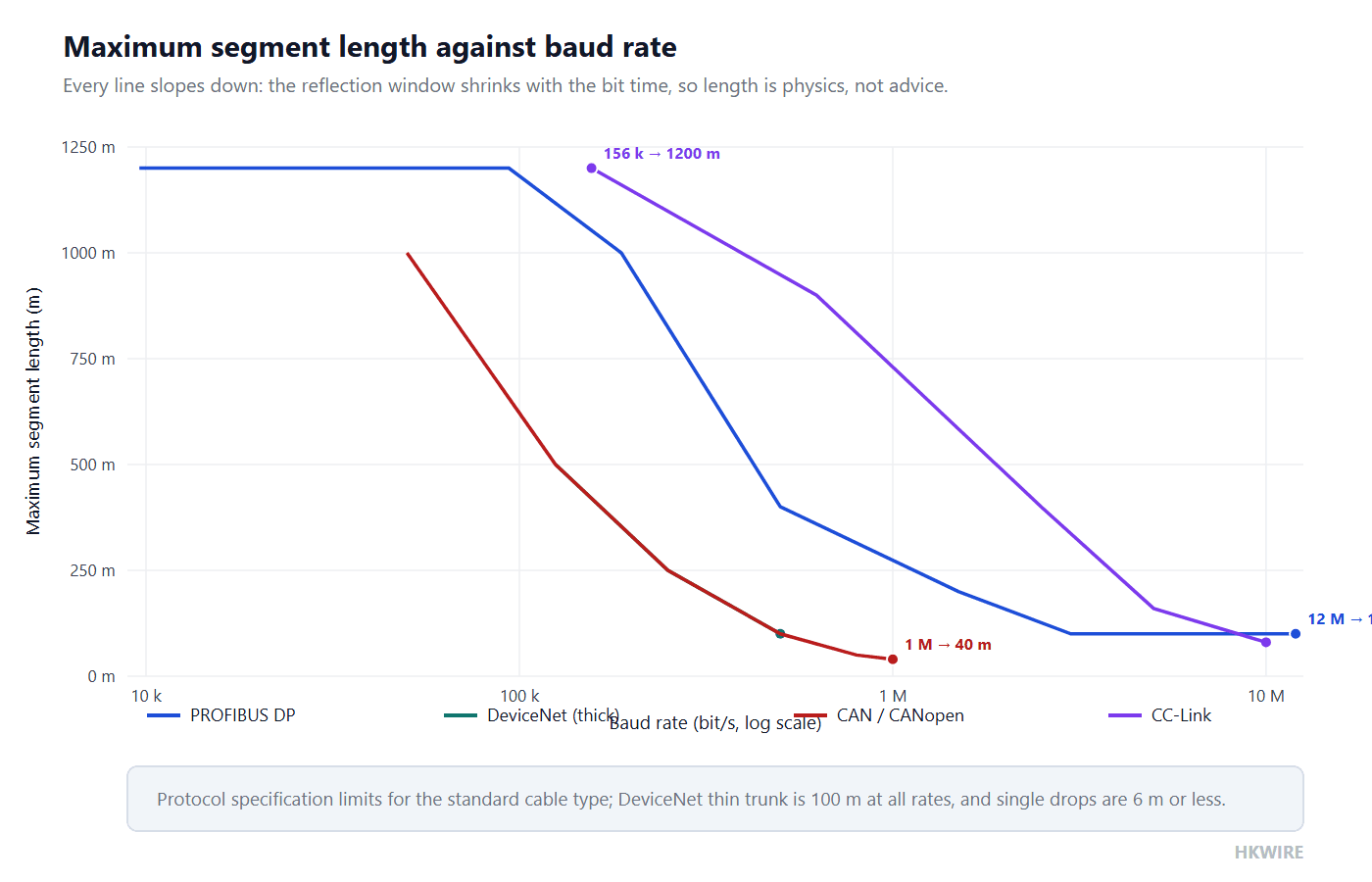
Every fieldbus has a table that pairs baud rate with maximum segment length, and it is tempting to read the short lengths as recommendations. They are not. At high bit rates the time it takes a signal to travel to the end of the cable and reflect back becomes comparable to the bit time itself, and beyond a certain length the reflection arrives while the transmitter is still sending the next bit. That is a physics limit, and no repeaterless cable, however good, gets around it.
| Fieldbus | Key length-versus-baud pairs |
|---|---|
| PROFIBUS DP | 9.6 / 19.2 / 45.45 / 93.75 kbit/s → 1200 m; 187.5 k → 1000 m; 500 k → 400 m; 1.5 M → 200 m; 3 / 6 / 12 M → 100 m |
| DeviceNet, thick trunk | 125 k → 500 m; 250 k → 250 m; 500 k → 100 m; thin trunk 100 m at all rates; single drop ≤ 6 m |
| CAN / CANopen | 1 M → 40 m; 800 k → 50 m; 500 k → 100 m; 250 k → 250 m; 125 k → 500 m; 50 k → 1000 m |
| CC-Link | 156 k → 1200 m; 625 k → 900 m; 2.5 M → 400 m; 5 M → 160 m; 10 M → 80 m (100 m at Ver. 1.10) |
These are the protocol-specification segment limits for the standard cable type; the pattern — distance shrinks as baud rises — is the same physics in every bus.
Read the extremes and the rule writes itself. PROFIBUS runs 1200 m at 9.6 kbit/s but only 100 m at 12 Mbit/s; CAN runs 1000 m at 50 kbit/s but only 40 m at 1 Mbit/s; CC-Link spans 1200 m at 156 kbit/s and 80 m at 10 Mbit/s. Every time the baud rate climbs an order of magnitude, the segment length collapses, because the reflection window shrinks with the bit time. The correct response to a “cable is too short” problem is a repeater or a slower rate, not a longer or “better” cable.
RS-485 states the same law as a rule instead of a table. Up to 100 kbit/s an RS-485 link may run 1200 m; above that, the distance falls in inverse proportion to the rate, so a 1 Mbit/s link is good for roughly 120 m. The numbers differ from PROFIBUS and CAN because RS-485 is a generic physical layer rather than a protocol with a fixed cable type, but the physics is identical: the bit time sets the reflection window, and the window sets the ceiling.
DeviceNet adds two mechanical limits the other buses do not express the same way. The network supports up to 64 nodes, with MAC IDs 0 through 63, on a single trunk, and the devices attach through drop lines that are individually limited to 6 m because every drop is a stub and every stub is a reflection source. The trunk itself comes in two grades: a thick trunk that reaches 500 m at 125 kbit/s, 250 m at 250 kbit/s and 100 m at 500 kbit/s, and a thin trunk limited to 100 m at every rate. Choosing the thick trunk is a length decision, not a quality decision — the thin cable is perfectly valid for short runs.
6. Termination: the component that absorbs the reflection
Reflection does not disappear just because the impedance is right; it disappears because the line ends in a termination that equals the line’s impedance. Each bus terminates differently, and the difference is worth reading, because the termination is where a network that “should work” often does not.
| Fieldbus | Termination network | Why it is built that way |
|---|---|---|
| PROFIBUS DP | 390 Ω (A to +5 V) + 220 Ω (A–B) + 390 Ω (B to GND) | three resistors give 150 Ω across the pair while biasing both lines to a defined idle level |
| DeviceNet | 121 Ω (1%, 1/4 W) at each end | matches the 120 Ω pair with a standard value plus bias |
| CAN / CANopen | 120 Ω (at least 1/4 W) at each end | ISO 11898 calls for a terminator at both physical ends only |
PROFIBUS uses a three-resistor network so the terminator doubles as the bus bias; DeviceNet and CAN use a single resistor at each end of the trunk.
Two rules fall out of that table. First, the terminator must be at the physical ends of the trunk, nowhere else, and exactly the number the protocol calls for — two ends means two terminators, not one and not three. Second, a terminator is not a resistor of “roughly the right value”; PROFIBUS needs the three-resistor network because the pair must idle at a defined bias level, and substituting a lone 150 Ω resistor removes that bias and can make the bus float to an undefined state when no one is transmitting. When a network runs for a while and then stops, the termination is the second thing to check, right after the cable.
Read the PROFIBUS network as three resistors doing two jobs. The 220 Ω across the pair sets the 150 Ω differential termination, while the two 390 Ω resistors, one to +5 V and one to ground, bias the two lines so that when no station is transmitting the bus rests at a defined idle level that every receiver recognizes as a valid state. Without that bias the lines float, and a floating bus is interpreted differently by different transceivers — one of the reasons a “terminated” PROFIBUS segment built with a lone resistor still misbehaves in service.
7. Type A cable: the electrical parameters that make a cable “able to run”
Impedance alone is not the whole cable. PROFIBUS defines a Type A cable — a single-pair shielded twisted pair — and pins down the electrical parameters that make it actually capable of carrying the signal over the rated distance. Those parameters are the difference between a cable that is “a twisted pair” and a cable that is “a PROFIBUS cable”.
| Parameter | Type A requirement | What it controls |
|---|---|---|
| Characteristic impedance | 150 Ω (135–165 Ω, 3–20 MHz) | reflection at junctions and terminations |
| Loop resistance | ≤ 110 Ω/km | the DC drop along the run, and therefore how far a segment can go before the signal level sags |
| Capacitance | ≤ 30 pF/m | edge rounding at high baud rates |
The Type A loop-resistance and capacitance limits come from the PROFIBUS DP cable specification and are the hard numbers that separate a compliant fieldbus cable from a look-alike.
The loop resistance matters more than most people expect. At 110 Ω/km a long run still drops measurable voltage, and the transceiver at the far end has to work with what is left after both conductors. Put it into a number: a 500 m PROFIBUS segment built from Type A cable has a loop resistance of at most 500 m × 110 Ω/km = 55 Ω, and that resistance sits in series with the signal. The transceiver must drive its differential voltage through both conductors and still leave a recognizable level at the far end, which is why the standard couples the resistance limit to the distance table — exceed the resistance and the far end runs out of signal, however clean the waveform.
The 30 pF/m capacitance limit is the high-frequency one: capacitance rounds off the square edges of the signal, and past a certain point the receiver cannot tell a one from a zero at the top baud rate. The same arithmetic applies. At 30 pF/m, a 100 m segment presents about 3 nF of shunt capacitance across the pair, and that capacitance must be charged and discharged by the transceiver on every transition. Double it and the edges round off enough that, at 12 Mbit/s, successive bits blur together. That is why a cable that is “a twisted pair” but not impedance- and capacitance-controlled passes at 9.6 kbit/s and fails at 12 Mbit/s — the difference is not the cable’s honesty, it is the bit time. “It looks like a shielded twisted pair” fails precisely here, because a cable that meets neither limit will pass a continuity test and still not carry 12 Mbit/s.
8. Selecting a fieldbus cable: a checklist
- Name the protocol first, because the impedance is protocol-specific: 150 Ω for PROFIBUS, 120 Ω for DeviceNet/CAN/RS-485, 110 Ω for CC-Link.
- Confirm the cable type — for PROFIBUS, a Type A single-pair shielded twisted pair with loop resistance ≤ 110 Ω/km and capacitance ≤ 30 pF/m.
- Check the segment length against the baud rate you actually plan to run, using the protocol’s own table, and leave margin rather than running at the limit.
- Fit the correct termination at the physical ends only: the PROFIBUS 390/220/390 network, or the 121 Ω DeviceNet / 120 Ω CAN resistor.
- Keep drop lines and stubs inside the protocol limit — DeviceNet single drops are 6 m maximum — because every stub is a reflection source.
A note on the shield, because it is part of the impedance story. A fieldbus cable is shielded, and the shield works only if it is continuous through every connector and grounded the way the protocol specifies — usually at one point, to avoid ground loops. A broken shield at a single junction leaves the pair exposed to noise and, worse, changes the effective impedance at that point, turning the junction into yet another reflection source. When a network passes a continuity test but fails intermittently, the shield path is the first place to look after the terminators.
Where the fieldbus meets the device, the connector has to preserve the same shield and impedance continuity — see our M8 and M12 circular connectors for the device end, and our guide to DIN 43650 valve connectors for the valve-actuator side of the same machine. If the plant runs a mix of fieldbus and Ethernet, keep the two cable families separate: our Ethernet patch cords are built to a different impedance and pair geometry, and they do not substitute for a fieldbus trunk.
9. Five things a general guide will not tell you about a fieldbus cable
- Impedance is a number you can put into an equation. A 100 Ω cable on PROFIBUS gives Γ = 0.2 — 20% reflection — and on DeviceNet gives 0.091. The impedance is not a marketing badge; it is the input to a reflection calculation.
- The 150 / 120 / 110 Ω values are not interchangeable. A 120 Ω RS-485 cable run on PROFIBUS is a 20% reflection, and the network fails at the top baud rate even though the cable is excellent for its own bus.
- A terminator absorbs reflection; it is not a “resistor of about the right value”. PROFIBUS needs the 390 + 220 + 390 three-resistor network because it doubles as the bus bias. Missing or misplaced terminators are the classic intermittent fault.
- Segment length versus baud rate is a physics ceiling. PROFIBUS drops from 1200 m to 100 m between 9.6 kbit/s and 12 Mbit/s, and CAN from 1000 m to 40 m. These are not suggested maxima you can exceed with a better cable.
- “It looks like a twisted pair” is not a specification. A PROFIBUS Type A cable is defined by loop resistance ≤ 110 Ω/km and capacitance ≤ 30 pF/m as well as impedance. A pair that meets neither will pass a continuity test and still not carry the traffic.
How we help
Tell HKWIRE which fieldbus you are running, the baud rate and the segment layout, and we supply the cable — the correct impedance, the Type A parameters where they apply, and the assemblies that preserve the shield and the impedance right into the connector. We are certified to ISO 9001 and return RoHS and REACH material declarations per project. Standard fieldbus-to-device builds live under our M8 and M12 connectors, and anything unusual can start through custom development.
Frequently asked questions
Why does a fieldbus cable have a fixed impedance?
Because the cable is a transmission line, and its characteristic impedance decides what happens at every junction and terminator. A mismatch reflects part of the signal back into the transmitter. PROFIBUS is 150 Ω, DeviceNet/CAN/RS-485 are 120 Ω, and CC-Link is 110 Ω; the value is set by the cable’s geometry and materials through Z₀ = √(L/C).
What happens if I use a 100 ohm cable on PROFIBUS?
The reflection coefficient is (150 − 100)/(150 + 100) = 0.2, so 20% of the signal reflects at the junction. At low baud rates the network may limp along; at 12 Mbit/s it usually fails or errors out, because the reflected signal corrupts the next bit.
Are DeviceNet, CAN and RS-485 cables interchangeable?
They all run at 120 Ω, but that does not make the cables interchangeable. They differ in conductor count, shielding and the electrical parameters the protocol requires, so a cable rated for one is not automatically compliant for the others. Match the cable to the protocol, not just the impedance.
Why does segment length shrink as baud rate rises?
At higher bit rates the bit time is shorter, so the round-trip time for a signal to travel to the end of the cable and reflect back becomes comparable to a bit. Past a limit the reflection returns while the transmitter is still sending, so each protocol caps length at each baud rate. PROFIBUS runs 1200 m at 9.6 kbit/s but only 100 m at 12 Mbit/s.
How many terminators does a bus need?
Exactly as many as the protocol specifies, at the physical ends of the trunk only. DeviceNet uses a 121 Ω resistor at each end, CAN uses 120 Ω at each end, and PROFIBUS uses the 390 + 220 + 390 three-resistor network so the pair idles at a defined bias. One missing or one extra terminator is enough to break the network.
What makes a PROFIBUS cable “Type A”?
Type A is a single-pair shielded twisted pair with characteristic impedance 150 Ω (135–165 Ω), loop resistance at most 110 Ω/km and capacitance at most 30 pF/m. The loop resistance limits the DC drop and the capacitance limits edge rounding at high baud rates.
Is the 150 ohm value exact or a range?
It is a target with a tolerance. The PROFIBUS specification writes the cable as 150 Ω with an allowed 135–165 Ω over the 3–20 MHz range, which is ±10%. The terminator and the cable must both land inside that window.
Can I use an Ethernet patch cord as a fieldbus cable?
Generally no. Ethernet cable is built to a different impedance and pair geometry, and the two families are not substitutes. A fieldbus trunk needs the impedance, the Type A parameters and the termination of its own protocol, so keep fieldbus and Ethernet cabling separate.







