

Choosing conductors for an automotive wire harness looks like a gauge question and is really a temperature-budget question. “What size wire do I need?” is the question everyone asks first, and it cannot be answered until three earlier decisions are on the table: the insulation temperature class, the fuse that will protect the circuit, and the termination that will anchor it. A conductor that is correct at 8 A in free air is wrong at 8 A inside a taped bundle over a hot engine bay. This guide gives you the temperature classes to quote from ISO 6722, the one proportionality that explains every ampacity number, the SAE J1128 table that replaces the formula, and the checks that turn all of it into a harness specification you can defend in a design review.
One honest note before the detail. HKWIRE is certified to ISO 9001 and provides material declarations per project for RoHS and REACH; every automotive wire harness we ship is built to IPC/WHMA-A-620 workmanship requirements. We do not publish ampacity numbers we cannot trace to a standard, and we do not quote contact-resistance values that belong to a terminal maker — where a number is a supplier property, we say so and point you at the data sheet.
1. Why temperature class comes first in an automotive wire harness
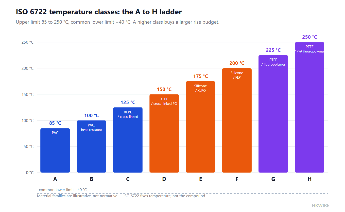
ISO 6722, the road-vehicle standard for single-core cables, divides insulation systems into temperature classes A through H, and into two voltage ratings: 60 V and 600 V. The class letter fixes the maximum continuous conductor temperature; the lower limit is −40 °C across the board. The class you choose is the single input with the largest effect on how much current a given copper cross-section is allowed to carry, which is why it belongs at the front of the selection process and not after the gauge has been guessed.
| Class | Upper temperature limit | Common lower limit | What a higher class buys you |
|---|---|---|---|
| A | 85 °C | −40 °C | Baseline cabin circuits |
| B | 100 °C | −40 °C | Warmer interior and underhood edges |
| C | 125 °C | −40 °C | Engine bay circuits away from exhaust heat |
| D | 150 °C | −40 °C | Higher underhood temperatures |
| E | 175 °C | −40 °C | Near heat sources |
| F | 200 °C | −40 °C | Exhaust-adjacent routing |
| G | 225 °C | −40 °C | Extreme thermal zones |
| H | 250 °C | −40 °C | Highest thermal zones |
Temperature classes per ISO 6722. The standard fixes temperature and voltage rating, not the compound: the material family behind each class is a supplier decision.
The two voltage ratings deserve a word as well. The 60 V rating covers the classic 12 V and 24 V board-net circuits that make up most of an automotive wire harness; the 600 V rating exists for the high-voltage circuits that air-conditioning compressors, DC-DC converters and electric drivetrains bring into the same vehicle. Class and voltage rating are independent choices — a 600 V cable does not imply a higher temperature class, and a class H cable says nothing about its dielectric rating. A specification that names one without the other is half a specification.
The classes exist for one reason, and it is worth stating plainly: they exist because a temperature-rise budget is the input to ampacity. The standard itself carries no current table. What it gives you is the ceiling that the ceiling of your thermal budget is named against. A class C insulation tolerates a 100 K rise over a 25 °C ambient; a class A insulation tolerates only 60 K. Same copper, different permitted rise, different permitted current — and the −40 °C floor in every row is a reminder that cold bending and cold impact are separate requirements, proven by separate tests, not by the class letter alone.
For the working document, the ISO 6722 project page at the Serbian standards body is a usable public reference for scope and class list; the purchased standard remains the authority for the clauses you cite on a drawing.
2. The one proportionality behind every ampacity number
Steady state, a conductor converts current into heat at I²R, the resistance of a fixed length falls as the copper cross-section grows, and the heat leaves through surfaces whose effectiveness changes with temperature. Compress all of the thermal physics into one constant and you get the proportionality every ampacity argument rests on:
ΔT ∝ I² / A
where ΔT is the temperature rise above ambient, I the current and A the copper cross-section. It is a proportionality, not a design formula: the hidden constant absorbs convection, radiation, bundling, conduit and every other path the heat actually takes. Its two legitimate uses are comparing like with like, and checking that a table value points in the physical direction. In an automotive wire harness, where the conductor spends its life inside tape and conduit next to other warm wires, that hidden constant is precisely the part the formula cannot know.
Worked example: 18 AWG from 60 °C to 105 °C insulation
Hold the conductor constant (18 AWG, 0.82 mm²) and swap the insulation from a 60 °C class to a 105 °C class, with a 25 °C ambient assumed throughout.
| Step | Expression | Result |
|---|---|---|
| Permitted rise, 60 °C insulation | 60 − 25 | 35 K |
| Permitted rise, 105 °C insulation | 105 − 25 | 80 K |
| Current scales with the square root of rise | √(80 / 35) | × 1.51 |
| Formula prediction | 6 A × 1.51 | ≈ 9.1 A |
| SAE J1128 table value, 18 AWG at 105 °C | from the table | 8 A |
The 6 A and 8 A anchor values are the SAE J1128 entries for 18 AWG; only the ratio 1.51 comes from the proportionality.
3. Reading the SAE J1128 table, and knowing its limits
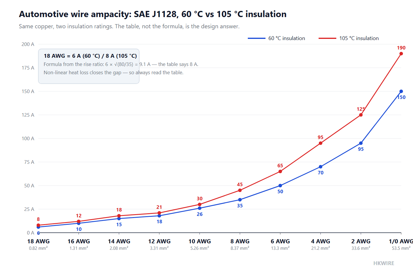
ISO 6722 contains no ampacity table; it is a construction and test standard for the cable itself. The table most of the industry reaches for is SAE J1128, which publishes continuous ratings for low-temperature and high-temperature insulation. Treat it as a reference baseline rather than a verdict: the final number for a production automotive wire harness is the wire supplier’s derating curve applied to the bundle conditions, because nobody’s table knows your conduit, your ambient or your grouping.
| Gauge | Copper area | Continuous rating, 60 °C insulation | Continuous rating, 105 °C insulation |
|---|---|---|---|
| 18 AWG | 0.82 mm² | 6 A | 8 A |
| 16 AWG | 1.31 mm² | 10 A | 12 A |
| 14 AWG | 2.08 mm² | 15 A | 18 A |
| 12 AWG | 3.31 mm² | 18 A | 21 A |
| 10 AWG | 5.26 mm² | 26 A | 30 A |
| 8 AWG | 8.37 mm² | 35 A | 45 A |
| 6 AWG | 13.3 mm² | 50 A | 65 A |
| 4 AWG | 21.2 mm² | 70 A | 95 A |
| 2 AWG | 33.6 mm² | 95 A | 125 A |
| 1/0 AWG | 53.5 mm² | 150 A | 190 A |
Continuous ampacity per SAE J1128 for 60 °C and 105 °C insulation; production harness ratings must follow the wire supplier’s derating curve for the actual bundle. The underlying gauge and ampacity numbers are published in the SAE standards.
Worked example: sizing for a 55 W load on a 12 V rail
| Step | Expression | Result |
|---|---|---|
| Load current | 55 W / 12 V | 4.6 A |
| Candidate conductor | 18 AWG, 105 °C class | 8 A rating → margin 8 / 4.6 ≈ 1.7 |
| Steadier choice | 16 AWG, 105 °C class | 12 A rating → margin ≈ 2.6, plus a voltage-drop cushion |
Both rows clear the 8 A and 12 A table values above; the choice between them is made by voltage drop and mechanical robustness, not by ampacity alone.
Note what this example deliberately does not do: it does not treat the 8 A as a number you may consume in full. Continuous design current should sit below the table value by whatever margin your bundle, ambient and duty cycle demand. And note the division of labor between this guide and our earlier one: ampacity asks how hot the copper may get; voltage drop asks how much of the supply the load actually receives. A conductor can pass one check and fail the other. That second calculation, including the arithmetic, is set out in our guide to voltage drop, ampacity and cable sizing.
One more reading skill: the two columns are two different products, not two moods of one product. A 60 °C column value belongs to a cable whose insulation system has qualified at that class; you may not take the 105 °C number and assume the same part number will deliver it. On a real automotive wire harness the class is written next to the gauge on the drawing for exactly this reason — a “18 AWG, class C” callout and a “18 AWG, class A” callout are two different cables with two different current ratings, and a purchasing department that orders on gauge alone has discarded half the specification.
4. Fuse coordination: the fuse must open before the wire does
Every ampacity table earns its keep through one rule: the fuse rating must not exceed the continuous current rating of the conductor it protects. If the fuse is larger, the overload that was supposed to open the fuse instead cooks the insulation, and the harness fails from the inside out. SAE J1128 publishes a maximum-fuse column next to its ampacity values precisely to make this coordination a lookup rather than an argument; the fuse devices themselves are covered by the ISO 8820 series for blade-type fuses.
Worked example: completing the 55 W circuit
| Step | Reasoning | Result |
|---|---|---|
| Conductor on the table | 18 AWG, 105 °C class, continuous rating | 8 A |
| Fuse constraint | rating ≤ conductor continuous rating | ≤ 8 A |
| Standard size just below | next standard blade value not exceeding 8 A | 7.5 A fuse |
| Load check | 4.6 A running current stays well under 7.5 A | circuit works and is protected |
Standard blade-fuse ratings step 5 A, 7.5 A, 10 A, 15 A; 7.5 A is the largest standard value that stays under the 8 A conductor rating.
5. Crimp pull force is measurable; contact resistance is not (in general)
Terminations are where an automotive wire harness actually fails, and the standards treat the two termination numbers very differently. Crimp tensile strength has hard, published minimums in IPC/WHMA-A-620, section 19, scaled by gauge. Contact resistance does not: there is no authoritative generic value, because the number depends on the terminal geometry, plating, wire count and crimp height of the specific part. Quoting a universal contact resistance is the fastest way to write a specification that a supplier cannot honor.
| Gauge | Minimum crimp pull-off force, IPC/WHMA-A-620 §19 |
|---|---|
| 22 AWG | 36 N |
| 20 AWG | 58 N |
| 18 AWG | 89 N |
| 16 AWG | 133 N |
| 14 AWG | 222 N |
| 12 AWG | 311 N |
Minimum untinned-strand pull-off values by gauge; the acceptance value for a specific terminal is set by the terminal maker’s specification, which may be stricter.
Crimping well is also a process discipline, not just a number. The pull-off minimums above are acceptance values for qualified samples, achieved by setting crimp height inside the terminal maker’s window and verifying it on production tooling — a harness shop that measures pull-off force only when something goes wrong is sampling its worst days. On an automotive wire harness drawing, “built to IPC/WHMA-A-620” means the workmanship standard is the routine check, not the rescue.
6. Thin-wall insulation: less material, more margin
Automotive primary wire comes in conventional, thin-wall and ultra-thin-wall builds — the industry naming follows the DIN 72551 family, with FLRY-type thin-wall insulation at roughly 0.20–0.45 mm and FLUY-type ultra-thin-wall at roughly 0.16–0.20 mm (supplier conventions rather than ISO 6722 wording, which sizes wall by conductor cross-section). The point of thin walls is not cost. Thinner insulation means a smaller, lighter cable for the same conductor; it also puts the heat source closer to the surface, which is why thin-wall builds carry the ampacity rows in the tables above. Cable maker LEONI quantifies the effect for its ultra-thin-wall FLUY against conventional FLRY: about 11 % smaller diameter and 7 % lighter.
The trade is mechanical. A thinner wall gives up abrasion margin, which is why thin-wall wire almost always travels inside conduit or under tape in the sections that follow. If a quote prices ultra-thin-wall wire as if it were a cheaper build, ask whether the protection plan was priced with it. The honest way to treat thin-wall in an automotive wire harness specification is as a paired decision: the wall class and the protection family are chosen together, and either one without the other is an incomplete design.
7. Protecting the bundle: conduit, tape and abrasion
The bundle is where an automotive wire harness lives or dies, because the bundle outlives any single wire only if it is engineered as its own system. The material temperature ranges below are supplier conventions for the common protection families, and OEM harness specifications — VW’s LV 312, GM’s GMW 16700, Ford’s WSS-M99P30 — decide which family appears on which branch of a production vehicle.
| Protection family | Nominal temperature range | Where it earns its place |
|---|---|---|
| PP corrugated conduit | −40 to +100 °C | General underbody and engine-bay branching, good abrasion per cost |
| PA6 / PA12 corrugated conduit | up to +150 °C | Hot zones where PP softens |
| PVC tape | 85–105 °C | Bundle wrapping, noise damping, low cost |
| PET fleece tape | per supplier grade | Rattle suppression in cabin routings |
| PET cloth tape | 125–150 °C | Abrasion resistance with heat, underhood edges |
Nominal ranges as quoted by protection-component suppliers; the governing document on a production harness is the OEM specification, and the IPC/WHMA-A-620 acceptance standard covers tape, conduit and loom workmanship.
Verification is by test, and the two names to know are mechanical: ISO 16750-3 for the environmental loads of electrical equipment in road vehicles — sine and random vibration, shock, drop, scraping abrasion and gravel impact — and ISO 16750-3:2023 is the current edition. ISO 6722 adds its own abrasion requirement in clause 5.12 for the cable itself. The two tests also interact in service in a way neither catches alone: a conduit that passes abrasion on the bench can still saw through a branch where vibration keeps the contact alive, and a bundle that survives vibration can still chafe through where the routing left too little slack. A bundle that has only been inspected, never vibrated, is an assumption, not a design.
8. A harness specification you can defend
- Class first. Fix the ISO 6722 temperature class (and the 60 V or 600 V rating) from the hottest point of the route, not the average ambient. The hottest point is usually a bundle in still air near a heat source.
- Current from the table. Take the continuous rating from SAE J1128 or the supplier’s curve, then derate for bundling and ambient. Never consume the table value in full.
- Fuse under the wire. Pick the largest standard ISO 8820 blade rating that does not exceed the derated conductor rating.
- Termination by test. State crimp pull-off per IPC/WHMA-A-620 §19 minimums, and specify contact resistance as “per terminal maker’s data sheet” with a four-wire measurement requirement.
- Protection as a system. Choose conduit and tape families against the OEM harness specification, with temperature ranges from the supplier data, and require ISO 16750-3 vibration evidence where the route demands it.
- Cold end checks. The −40 °C lower limit is common to every class, but cold bend and cold impact are separate tests; require them explicitly for the coldest deployment.
HKWIRE builds every automotive wire harness to IPC/WHMA-A-620 and works from customer route data to propose class, gauge, protection and termination as one coherent package; the automotive cable and wire harness range covers the standard builds. Where the insulation must also survive oil exposure, the material decision continues in our guide to oil-resistant cable material selection.
9. Five things a general guide will not tell you
- The formula predicts about 9.1 A where the table says 8 A — and the table wins. The √(80/35) = 1.51 extrapolation from the rise ratio is directionally right and numerically wrong, because heat loss is not linear in temperature. That gap is the entire argument for treating ampacity tables, not formulas, as design documents.
- The A–H classes exist because of the rise budget. A higher class is not a “better” wire; it is a wire permitted a larger temperature rise, which converts directly into more current for the same copper. The −40 °C floor in every class is the other half of the budget.
- Fuse coordination has no single ISO clause. “Fuse rating ≤ conductor rating” is a design principle made executable by SAE J1128’s maximum-fuse column and ISO 8820 fuse hardware. Quote the logic and the two documents, not a phantom ISO sentence.
- Crimp pull force is a standard number; contact resistance is not. IPC/WHMA-A-620 §19 publishes gauge-scaled minimums from 36 N at 22 AWG to 311 N at 12 AWG, while contact resistance has no authoritative generic value — it lives in the terminal maker’s data sheet.
- Thin-wall insulation is a thermal upgrade, not a cost cut. FLUY-type ultra-thin walls run about 11 % smaller and 7 % lighter than conventional builds (LEONI data) while holding the same ampacity rows — and they surrender abrasion margin, so the protection plan must be specified with them, not after them.
How we help
Send us the route, the load schedule and the ambient profile for your automotive wire harness, and HKWIRE returns a conductor and protection proposal with the standards named next to every number — class per ISO 6722, ratings per SAE J1128 with the derating assumptions written out, terminations per IPC/WHMA-A-620, and material declarations provided per project for RoHS and REACH. Open a project through custom development when the harness needs a build we do not hold in stock.
Frequently asked questions
Does ISO 6722 include an ampacity table?
No. ISO 6722 is a construction and test standard for road-vehicle cables: temperature classes A to H, voltage ratings of 60 V and 600 V, and the tests that prove the construction. Continuous current ratings come from references such as SAE J1128 and, for a production harness, from the wire supplier’s derating curve applied to your bundling and ambient.
Why does the formula give 9 A when the table says 8 A for 18 AWG?
The proportionality between rise and current assumes the heat-loss constant stays fixed, and it does not: radiation and convection both change with temperature, and a real harness adds insulation, tape and conduit to the thermal path. The square-root extrapolation from 6 A to about 9.1 A points the right direction; the SAE J1128 value of 8 A is the one to design with.
Which temperature class should an engine-bay circuit use?
Class C (125 °C) is a common starting point for engine-bay branches away from exhaust heat, class D (150 °C) or higher closer to sources — but the deciding input is the measured temperature at the hottest point of the actual route, not a zone label. Choose the class from the route, then confirm the compound in the supplier’s data sheet.
Can I fit a bigger fuse if the original one keeps blowing?
Only if the conductor rating still exceeds the new fuse. The fuse exists to open before the wire overheats, so its rating may never exceed the continuous rating of the conductor it protects. A fuse that repeatedly blows is reporting a load current nobody measured, a conductor that was downsized after the fuse was chosen, or a fault that deserves diagnosis.
What crimp pull force should I require for 16 AWG?
IPC/WHMA-A-620 section 19 sets a 133 N minimum pull-off value for 16 AWG, with the acceptance figure for a specific terminal set by the terminal maker’s specification, which may be stricter. State the standard, the gauge and the per-terminal specification together.
Is there a standard contact-resistance value I can put in a specification?
No. Contact resistance depends on the terminal geometry, plating, strand count and crimp height of the specific part, and no authoritative generic value exists. Specify a four-wire measurement on qualification samples and take the acceptance limit from the terminal maker’s data sheet.
Is thin-wall insulation just a way to sell less material?
The opposite. Thinner walls shorten the heat path, which is part of how thin-wall builds hold the ampacity rows in the standard tables, and they shrink diameter and weight — about 11 % and 7 % respectively for LEONI’s FLUY versus conventional FLRY. The cost is abrasion margin, which must be bought back with conduit or tape in the routing plan.
Do I still need an OEM harness specification if the cable meets ISO 6722?
Yes. ISO 6722 qualifies the cable; documents such as VW LV 312, GM GMW 16700 and Ford WSS-M99P30 define how the bundle is protected, routed and verified on a specific vehicle, including the vibration and abrasion evidence required under ISO 16750-3. The two layers answer different questions, and a production automotive wire harness needs both.







