M12 Bulkhead Panel Connector with Pigtail, A, D and X Coding
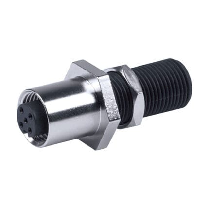
An M12 bulkhead panel connector takes sensor, fieldbus and industrial Ethernet wiring through an enclosure wall in one threaded penetration. A, B, D or X coding, front or rear mounting, solder terminals or a molded pigtail on the back. Cut-out confirmed per drawing.
Last updated: 13 September 2026
Overview
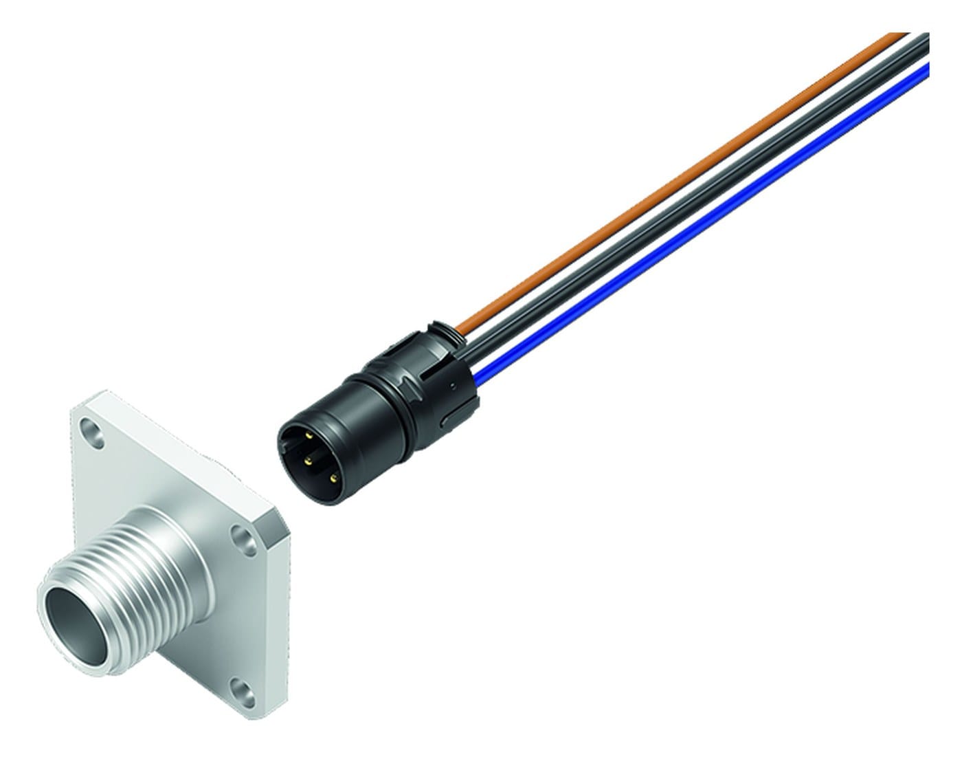
An M12 bulkhead panel connector is the standard way to get sensor, fieldbus and industrial Ethernet wiring through an enclosure wall. The threaded body passes through the panel and is clamped by a nut; one side presents the M12 mating face, the other side is either solder terminals or a molded pigtail. Keeping the transition at the wall rather than inside the cabinet means the cable gland and the terminal strip disappear together, and everything inside the enclosure becomes a single harness that plugs in.
Key Specifications
| Connector series | M12 bulkhead receptacle, front or rear mounting |
|---|---|
| Coding | A, B, D and X coding available (confirm coding against the existing receptacle) |
| Pole count | 4, 5, 8 and 12 positions (pending supplier confirmation per coding) |
| Mounting thread | M12, M16 or PG9 (pending supplier drawing) |
| Shell material | Nickel-plated brass or 316L stainless steel (pending supplier confirmation) |
| Inside termination | Solder terminals or molded PUR / PVC pigtail, 0.2 / 0.5 / 1 / 2 m |
| Ingress rating | IP67, IP68 and IP69K in mated condition (pending test reports) |
| Temperature range | -40 to +85 C (pending supplier datasheet) |
| Mating cycles | 100 to 500 depending on version (pending supplier datasheet) |
| Interface standard | M12 circular connectors per IEC 61076-2-101 |
| Typical use | Sensors, actuators, PROFINET, 10 gigabit industrial Ethernet, washdown zones |
| Shield transfer | Ground spring or shield contact to the panel, version dependent |
Coding decides what the bulkhead is for
M12 bodies share a thread, so the internal keyway is the only thing stopping a mismatch. The coding is set out in the IEC 61076-2 family: A, B, C and D in part 2-101, X in part 2-109, and the power codes in their own parts. All of them live in the same 12 mm M12 connector shell, which is exactly why the keyway matters. Read the code off the receptacle already on the machine before you order, because a plug that threads on but is not keyed for the coding will damage both halves.
| Coding | Positions | Carries | Where you will find it |
|---|---|---|---|
| A | 3 / 4 / 5 / 8 / 12 | DC power and sensor signals, 24 V class | Proximity and photoelectric sensors, valve connectors, IO-Link |
| B | 5 | PROFIBUS-DP fieldbus | Legacy PLC and drive networks |
| D | 4 | 100 Mbit/s Ethernet | PROFINET, EtherNet/IP and EtherCAT drops on four-position receptacles |
| X | 8 | Up to 10 Gbit/s, Cat6A class | Machine vision, high-speed industrial Ethernet, OneNet style runs |
Note what the X-coded version does to the rest of the build. An eight-position shielded receptacle carrying 10 Gbit needs the shield carried through the panel and the pair twist kept as close to the contact as the termination allows. It is not a sensor connector with more pins; it is a different class of part that happens to share the thread. Our M12 X-Code Cat6A to RJ45 Shielded Industrial Ethernet Cable is the matching cordset for that case.
Front mount or rear mount: pick on the panel, not on the datasheet
This is the question that is answered too late. Front mounting is the default and keeps the nut and the gasket on the accessible side. Rear mounting is used where the assembly has to go in from inside the enclosure, or where an external flange would foul a door, a label or a wiping surface. The choice changes the cut-out, the panel thickness range and the side the gasket ships on.
| Front mounting | Rear mounting | |
|---|---|---|
| Installed from | Outside the enclosure | Inside the enclosure |
| Gasket sits | Between the flange and the outside face | Between the housing and the inside face |
| Typical panel | Thicker panels, standard sheet metal | Thin panels, often quoted up to about 3 mm on PCB versions |
| Best when | The nut has to be reachable for service | The outside face has to stay flat and clean |
| Watch out for | Flange fouling a door or a label | No access to re-torque without opening the box |
| Typical thread | M16 x 1.5 and M20 x 1.5 are widely quoted | M16 x 1.5 is widely quoted; M12 and PG9 also offered |
Panel thickness is the number that catches people out. The figures you will see quoted vary widely between versions, from a few millimeters on a PCB rear-mount body to well over ten on a heavy stainless front-mount housing, so confirm the window for the exact part before you commit the panel design. Overtightening a metal nut onto a painted panel cracks the coating and gives water a path under the seal, which is a failure that looks like a bad gasket and is not.
Shield transfer and the ground spring
Where the cable is screened, the screen has to land somewhere. On a bare metal panel the shell and the nut usually do the job; on a painted, powder-coated or anodized panel they do not, and a ground spring or a star washer under the flange is needed to bite through the finish. Mask the mounting area before the panel is coated if you can – it is cheaper than the washer and more reliable than hoping. For Ethernet codings this is not optional: a shield that stops at the wall turns a Cat6A run into an unshielded run at the point where it matters most.
Specifying this M12 bulkhead panel connector
- Coding and pole count – read them off the receptacle already on the machine.
- Mounting direction – front or rear, and the panel thickness at that point.
- Mounting thread – M12, M16 or PG9, matched to your cut-out tooling.
- Shell material – nickel-plated brass or 316L stainless for washdown and food zones.
- Inside termination – solder terminals or molded pigtail, and the jacket.
- Shield transfer – bare, painted or anodized panel, and whether a ground spring is needed.
- Quantity, and whether this is a prototype or a production order.
Where it gets installed
- Machine and cabinet walls carrying sensor and actuator wiring
- PROFINET drops on D-coded four-position receptacles
- Ten gigabit industrial Ethernet on X-coded eight-position receptacles
- Washdown zones in food and beverage plants, alongside our M12 IP69K Washdown Cable with Stainless Steel Coupling Nut
- Junction boxes and distribution blocks feeding several field devices
Ratings pending confirmation
Pole counts, coding options, shell material, pigtail lengths, ingress ratings, temperature range and mating cycles for this range are taken from the published data of comparable M12 products and are design targets until the supplier datasheet is on file. The mating face follows the M12 connector standard, so these assemblies are intended for use with the same coding on the plug side, without implying any endorsement or supply relationship.
Workmanship and testing
IPC/WHMA-A-620 Class 3 sets the workmanship bar here, backed by an ISO 9001 quality system and a 32 to 12 AWG termination range. Nothing is packed until continuity and pinout have been verified. Where an ingress rating is specified, seal checking on the batch is available.
Custom builds and ordering
Prototypes run from 5 pcs with a 3 working day turnaround; volume orders start at MOQ 500 pcs and ship 14 working days after sample sign-off. If the build needs tooling we do not already hold, add roughly 10 working days. OEM and ODM orders ship under your part number and labeling, and material certificates and first-article reports are available on request.
Related M12 and panel hardware
- M12 12-Pin Bulkhead Cable with Flying Leads
- M12 D-Code 4-Pin PROFINET Industrial Ethernet Cable
- M12 A-Coded PVC/PUR Straight or Right-Angle Extension Cable
- Cat6A M12 X-Code Link Cable, X-Coded 8-Pin Both Ends, IP67
- SPE Bulkhead Panel Connector for 10BASE-T1L Field Devices
- IP67 Keystone Panel Frame for Field-Replaceable RJ45 Modules
Full ranges: circular M8 and M12 cable and panel mount cable.
Frequently Asked Questions
How do I tell which coding I have?
The code is usually molded into the connector body, and the keyway position identifies it from the front face. Send a photo of the receptacle and we will confirm coding, pole count and gender.
Front mount or rear mount – which should I choose?
Front mounting if the nut has to be reachable for service and the panel is thick enough. Rear mounting if the outside face has to stay flat or the assembly has to go in from inside. Confirm the thickness window for the exact part.
Is X-coding interchangeable with D-coding?
No. The keying is different and so is the arrangement. An X-coded receptacle carries eight positions for 10 Gbit class Ethernet; a D-coded one carries four for 100 Mbit.
| Connector series | M12 bulkhead receptacle, front or rear mounting |
|---|---|
| Coding | A, B, D and X coding available (confirm coding against the existing receptacle) |
| Pole count | 4, 5, 8 and 12 positions class |
| Mounting thread | M12, M16 or PG9 class |
| Shell material | Nickel-plated brass or 316L stainless steel class |
| Inside termination | Solder terminals or molded PUR / PVC pigtail, 0.2 / 0.5 / 1 / 2 m |
| Ingress rating | IP67, IP68 and IP69K in mated condition |
| Temperature range | -40 to +85 C class |
| Mating cycles | 100 to 500 depending on version |
| Interface standard | M12 circular connectors per IEC 61076-2-101 |
| Typical use | Sensors, actuators, PROFINET, 10 gigabit industrial Ethernet, washdown zones |
| Shield transfer | Ground spring or shield contact to the panel, version dependent |
Related products

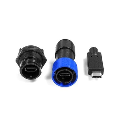
SPE Bulkhead Panel Connector for 10BASE-T1L Field Devices
An SPE bulkhead panel connector brings 10BASE-T1L single pair Ethernet and Power over Data Line into a field device box through one sealed penetration. IEC 63171-6 mating face or M8 coupling, front or rear mounting. The cut-out is smaller and the termination is faster than a four-pair Ethernet entry.