

The barrel plug, the coaxial DC power connector, looks trivial and gets specified last, usually by copying whatever was on the previous version. It is also a common cause of “the device works on the bench and browns out in the field”, because the plug is the one part of the power path whose resistance is not printed on the cable and not counted in any voltage-drop calculation. This guide covers the four decisions that matter (size, polarity, current rating, lock type) and then does the arithmetic almost nobody does: the voltage-drop budget for the interface itself.
HKWIRE builds DC plug power cables in slip-fit and screw-lock versions, so the numbers below are the ones we ask for in an RFQ. One idea is worth stating up front: the conductor is the easy half of a DC power lead, because conductor resistance scales with length and you can look it up in a table. The connector interface does not scale with anything, so on a short lead it is the biggest term in the budget.
What a barrel plug has to survive
A barrel connector is two concentric contacts: an outer sleeve and a center pin. The plug is the male half, the jack is the female half mounted on the equipment, and everything difficult about the part follows from that arrangement.
First, the contact is made by a spring, a spring finger or a leaf that is deflected when the plug enters. A spring contact has a small contact area, its force relaxes over time and with temperature, and it has no positive lock. Second, the connector is not polarized by its own geometry: the same plug will go into a jack wired either way round, so polarity is a convention you have to specify rather than a feature that protects you. Third, the rating is a property of the model, not of the size. These three facts are the source of nearly every field complaint about this connector, and each of them can be turned into a number.
The barrel plug is in the loop: budgeting the drop at the interface
Start with the formula that decides whether a DC power lead works, and note that it contains the connector explicitly:
V_drop = 2 x ( R_contact + R_crimp + R_wire_per_m x L ) x I
where L is the one-way cable length, R_wire_per_m is the resistance of one conductor per meter, R_contact is the resistance of one mated contact interface, R_crimp is the resistance of one conductor termination, and the factor of 2 covers the outbound and return legs of the loop. The budget test is:
V_drop / V_nominal <= budget, with 5 percent being the common engineering budget for a DC feed.
The factor of 2 is easy to get wrong, so be explicit about it. The outbound leg runs through the supply termination, the positive conductor and the center contact of the plug; the return leg runs through the sleeve contact of the same plug, the negative conductor and its termination. Each leg therefore carries one crimp and one contact interface, which is what the 2 multiplies. An extension lead with a barrel connector at each end doubles the bracket again, because each leg then carries two interfaces. TI makes the same point from the other direction when it budgets a USB cable: a typical cable interface contact resistance of about 30 mOhm becomes 0.12 Ohm in the loop, because there are four connections, two at each end, as described in this TI note on cable voltage droop.
Worked through: 12 V, 2 A, 1 m of 20 AWG
Inputs. Nominal 12 V, budget 5 percent = 600 mV, load current 2 A, one-way length 1 m, conductor 20 AWG. The conductor is 0.518 mm2, and with a copper resistivity of 0.017241 Ohm mm2 per meter at 20 degrees C the resistance of one conductor is 0.017241 / 0.518 = 0.0333 Ohm per meter, that is 33.3 mOhm per meter. The crimp is a copper barrel on a copper conductor, so the maximum permitted initial contact resistance is given by the IEC 60352-2 relation A = 0.4596 x C^-0.8843 in milliohms, with C the conductor cross-section in mm2. For C = 0.518: A = 0.82 mOhm. That is a maximum for a fresh joint; a correctly made crimp measures well below one milliohm, which is what makes a good crimp a negligible part of the budget. The standard is at IEC 60352-2, solderless crimped connections.
Step 1 – the three contact-resistance cases. There is no universal figure for a barrel interface, so run three: 10 mOhm as a best-case parameter for a clean, lightly used, well-plated contact; 30 mOhm as TI’s typical cable interface value; and 50 mOhm, which is the maximum one manufacturer publishes for a 5.5 x 2.5 mm jack, as in this DC power connector range.
Step 2 – the bracket for each case. With R_crimp = 0.82 mOhm and R_wire x L = 33.3 mOhm, the one-leg total is R_contact + 0.82 + 33.3 mOhm. For the three cases that is 44.1, 64.1 and 84.1 mOhm.
Step 3 – the loop and the current. Multiply by 2 for the return leg and by 2 A: 176.5, 256.5 and 336.5 mV respectively. Against a 600 mV budget that is 29, 43 and 56 percent. All three pass at 2 A.
| Case | Contact (mV) | Crimp (mV) | Conductor (mV) | Total drop (mV) | Percent of 12 V | Percent of the 600 mV budget |
|---|---|---|---|---|---|---|
| R_contact = 10 mOhm | 40.0 | 3.3 | 133.2 | 176.5 | 1.47 percent | 29 percent |
| R_contact = 30 mOhm | 120.0 | 3.3 | 133.2 | 256.5 | 2.14 percent | 43 percent |
| R_contact = 50 mOhm | 200.0 | 3.3 | 133.2 | 336.5 | 2.80 percent | 56 percent |
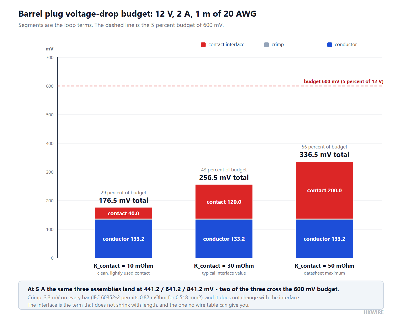
Read the second and third rows together. The crimp contributes 3.3 mV and does not change with the contact resistance; the conductor contributes 133.2 mV; the contact contributes between 40 and 200 mV. The interface alone spans more of the budget than either of the other two segments, and it is the one variable you cannot read off a wire table.
The same assembly at 5 A
Now hold everything constant except the current, and the picture inverts.
| Case | Drop at 2 A | Drop at 5 A | Percent of 12 V at 5 A | Contact share of the drop at 5 A | Verdict against a 5 percent budget |
|---|---|---|---|---|---|
| R_contact = 10 mOhm | 176.5 mV | 441.2 mV | 3.68 percent | 22.7 percent | Passes |
| R_contact = 30 mOhm | 256.5 mV | 641.2 mV | 5.34 percent | 46.8 percent | Fails |
| R_contact = 50 mOhm | 336.5 mV | 841.2 mV | 7.01 percent | 59.4 percent | Fails |
Two conclusions come out of this and neither of them is obvious from a catalog. First, a 1 m lead that comfortably passes at 2 A fails at 5 A with the same plug, and it fails because of the interface, not because of the wire. Second, the contact share of the total drop rises from 47 to 59 percent as the contact degrades, which means that on a 12 V rail the connector is not a detail – it is roughly half of the power-quality budget.
The short-lead trap
The reason people get caught is that they reason about length. Conductor drop scales with length, so shortening the lead looks like a fix. It is not, because the contact and crimp terms do not move. Fix the contact at the 30 mOhm TI quotes, hold the current at 2 A, and vary the length:
| One-way length | Conductor drop | Total drop | Contact share of the total | Comment |
|---|---|---|---|---|
| 0.1 m | 13.3 mV | 136.6 mV | 87.8 percent | The interface is almost the whole drop |
| 1.0 m | 133.2 mV | 256.5 mV | 46.8 percent | Roughly half each |
| 3.0 m | 399.6 mV | 522.9 mV | 22.9 percent | Conductor now dominant, still inside budget |
| 3.5 m | 466.2 mV | 589.5 mV | 20.4 percent | Within 11 mV of the budget |
| 5.0 m | 666.0 mV | 789.3 mV | 15.2 percent | Fails; the connector contributes 123.3 mV of the total |
So a 10 cm patch lead is not automatically safe. With a typical interface it spends 88 percent of its drop at the connector, and the fix is a better contact or a higher supply voltage, not a thicker wire. “The lead is short, it will be fine” is a dangerous sentence in a DC power design review. The budget runs out at 3.58 m of 20 AWG at this current, and by then the connector is still contributing 123.3 mV.
Two more effects worth budgeting
Temperature. The 33.3 mOhm per meter above is at 20 degrees C. Copper resistance rises by about 0.393 percent per kelvin, so the same conductor at a 75 degrees C conductor temperature is 40.5 mOhm per meter, about 22 percent more. On the 1 m case that moves the conductor segment from 133.2 to 162.0 mV, and it is the segment that grows with duty cycle.
Age and mating cycles. Contact resistance is not a constant, and the mechanism is wear rather than dirt. Plating wears through where the spring finger slides, and oxide and fretting corrosion build up in exactly that spot. A connector that measured 20 mOhm when new can measure 50 mOhm after a few thousand cycles, which is why a datasheet normally states both a life in cycles and a maximum contact resistance. Budget the value at end of life, not the value in the incoming inspection report. This is why insertion life is a voltage budget parameter and not a cleaning topic.
The thing that general guides, AI summaries and online calculators leave out. Conductor resistance and crimp resistance are the two terms everyone budgets, and they are the two terms that behave. The contact interface is the third term. It sits in the same series loop, it does not shrink when you shorten the cable, it grows with use, and its only specification is whatever the maker chose to publish. Ask for the maximum contact resistance and the rated life in cycles before you fix a size, and budget the end-of-life number rather than the new-part number.
1. Size: the barrel plug’s two diameters
A barrel plug is defined by two diameters, and both of them have to match: the outer diameter of the sleeve, which is the mating diameter of the shell, and the inner diameter of the center contact. Sizes are written OD x ID in millimeters.
| Size (OD x ID) | Standard family | Where it is used | Mechanical note |
|---|---|---|---|
| 2.35 x 0.70 mm | EIAJ-01 (RC-5320A) | Very small equipment, older handsets and headsets | The EIAJ sizes are banded to a voltage range, not only to a size |
| 3.5 x 1.3 mm | Common size, not part of the IEC 60130-10 type list | Compact and portable equipment | 3.5 x 1.35 mm also exists and is close enough to cause mis-specification |
| 4.0 x 1.7 mm | EIAJ-02 (RC-5320A) | Cameras, small peripherals, some laptop adapters | Same shell diameter as some 4.75 x 1.7 mm parts; check the ID as well |
| 5.5 x 2.1 mm | IEC 60130-10 Type A | The most widely used size: routers, cameras, LED supplies, development boards | Shares its 5.5 mm shell with the 2.5 mm variant |
| 5.5 x 2.5 mm | IEC 60130-10 Type A | Same equipment classes, higher-current models | Physically mates with a 2.1 mm jack, with a loose center contact |
| 6.0 x 2.1 mm | IEC 60130-10 Type B | Less common variant of the 5.5 mm family | Will not mate with a 5.5 mm jack |
| 6.3 x 3.0 or 3.1 mm | IEC 60130-10 Type D | Larger, higher-current equipment | Different shell diameter again; not interchangeable with 5.5 mm |
| 6.5 x 4.3 mm | EIAJ-05 (RC-5320A) | Some laptop and radio chargers | Voltage-banded like the other EIAJ sizes |
| 7.4 x 5.0 mm | Laptop size, often with a third data pin | Laptop and handheld vacuum chargers | The third pin carries a communication signal, so a plain 2-contact plug will not charge |
Two traps live inside that table. The first is the shared shell: a 5.5 x 2.1 mm plug and a 5.5 x 2.5 mm plug have the same outer diameter, so either one will enter either jack. What changes is the center contact. A 2.1 mm plug in a 2.5 mm jack leaves the center contact loose, which produces the intermittent operation and local heating you would expect from a loose spring contact; a 2.5 mm plug does not fit a 2.1 mm jack at all. So “it plugs in” is not a compatibility test. Both diameters have to match.
The second trap is that the size designation describes the mating diameter, not the physical shell. A jack sold as 5.5 x 2.5 mm is specified against a 5.5 mm mating plug, but the molded body around it can be appreciably larger: one widely used through-hole jack lists a 2.50 mm inner contact, a 5.50 mm recognized mating diameter and an actual outer hole of 6.50 mm. If you are designing a panel aperture or a strain-relief boot, work from the maker’s physical drawing, not the size code. The families behind these sizes are IEC 60130-10 and EIAJ RC-5320A, and this DC power connector range lists them as they are actually sold; when the code and the drawing disagree, the drawing wins.
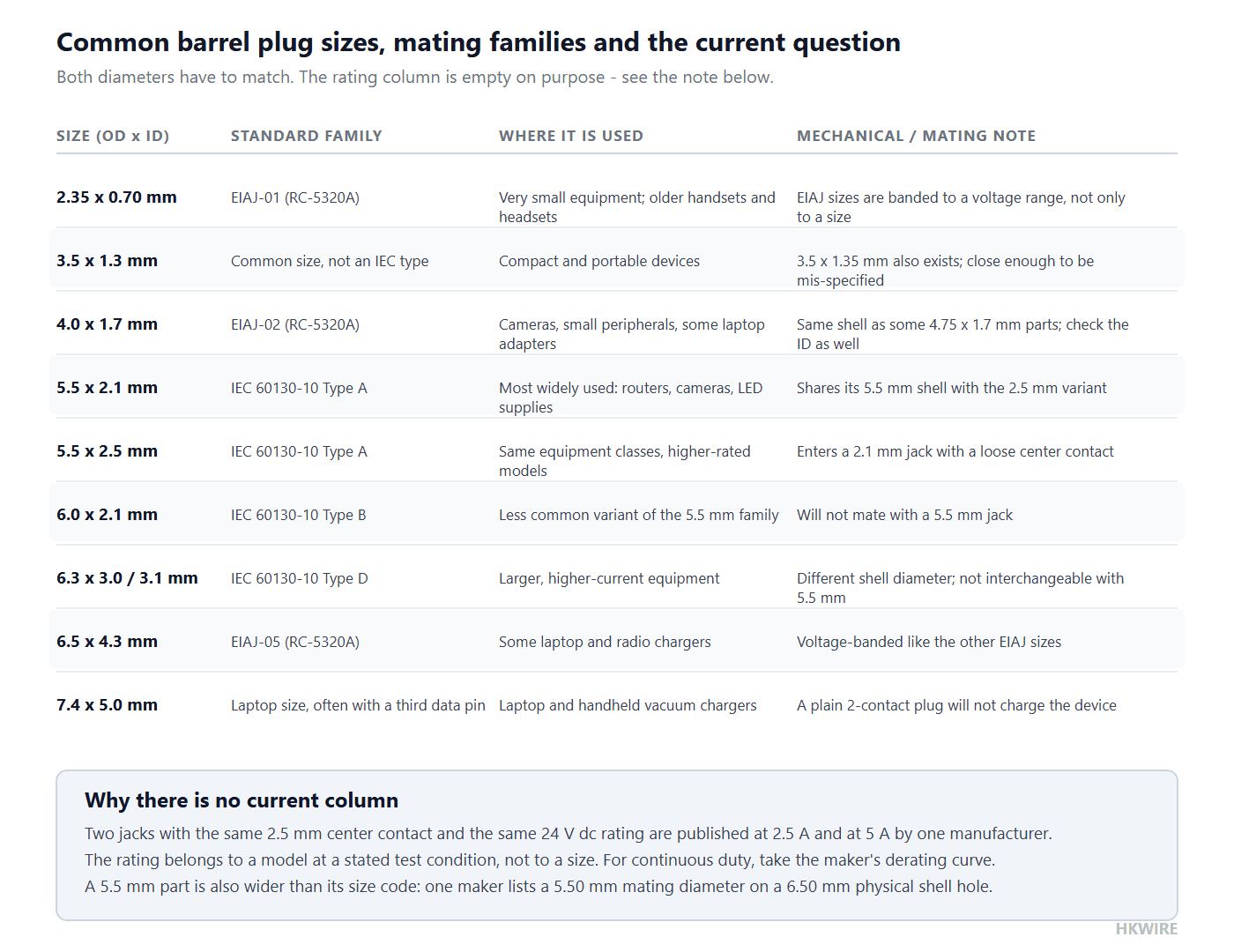
A 5.5 x 2.5 mm plug will physically fit a 5.5 x 2.1 mm jack, but the center contact is loose. Match both numbers, not just the shell.
2. Polarity
A barrel connector is not polarized by its geometry, so polarity is a wiring convention that both ends have to agree on. There are two, and they are not interchangeable:
- Center positive: the center contact carries the positive rail and the sleeve is the return. This is the common convention, used by most wall adapters and development boards.
- Center negative: the sleeve carries the positive rail and the center contact is the return. It is uncommon, mostly on legacy and some audio equipment.
Because the same plug fits a jack wired either way, reversing the pair reverses the supply, and most equipment will not survive that. Do not rely on “the convention is center positive” as a specification. Write the polarity on the drawing as a symbol and as a sentence, and mark the finished assembly so a technician replacing a supply cannot get it wrong. Where the equipment allows it, a keyed or mechanically polarized connector eliminates the risk entirely, which is often a better answer than a label.
3. Current rating
The current rating of a barrel plug is the number most often copied from one part to another, and it is the number least transferable. Published equipment ratings are set by a specific test condition chosen by the maker, and the same nominal size appears with very different numbers across models.
| Mating size | Published rated current | Published rated voltage | Published contact resistance | Published operating temperature | Stated life |
|---|---|---|---|---|---|
| 5.5 x 2.0 mm jack | 2.5 A | 24 V dc | 50 mOhm max | -25 to +85 degrees C | Per the maker’s datasheet |
| 5.5 x 2.5 mm jack | 2.5 A | 24 V dc | 50 mOhm max | -40 to +85 degrees C | Per the maker’s datasheet |
| 5.5 x 2.5 mm jack, higher-rated model | 5 A | 24 V dc | Per the maker’s datasheet | -25 to +85 degrees C | Per the maker’s datasheet |
Two parts in the same product line, with the same 2.5 mm center contact and the same 24 V dc rating, are published at 2.5 A and 5 A. Nothing about the size changed; the model changed. That spread is the whole argument for this rule:
Never use a size to infer a current rating. The rating belongs to a model, at a stated test condition, and for continuous duty the number that matters is the one on the maker’s derating curve. Ask for the curve, and ask what ambient temperature and what temperature rise it was measured at. If no curve is available, the honest answer is that the part has no usable continuous-current rating for your application.
There is a physical reason the curve matters more here than it does for a terminal block. The contact is a spring finger with a small contact area, and the housing is often a thermoplastic that softens well above the contact’s own limit. As current rises, the contact heats, spring force relaxes, contact resistance rises, and the heat rises again. That positive feedback is why a barrel connector operated above its continuous rating fails by softening and loosening rather than by a clean open circuit.
Once the interface is derated, size the conductor for the current and the length. That part is well behaved and has its own article on this site; the short version is that a long thin lead underperforms at the load even when every component is within its rating.
4. Lock type: keeping the barrel plug seated
Retention is a vibration question, not a feel question. A slip-fit barrel plug depends only on the friction of the spring contact, and under vibration that spring can let the pin walk, producing a micro-interruption too short for a multimeter and long enough to reset a processor.
| Type | Retention principle | Use when | What it costs you |
|---|---|---|---|
| Slip-fit barrel | Spring contact friction only | Bench and stationary equipment, or where the plug is removed often by hand | No positive retention; micro-interruptions under vibration |
| Threaded / screw-lock | A threaded collar turned onto a threaded jack | Mobile, vibrating, vehicle and field equipment | Slower to mate; needs a threaded jack on the device |
| Right-angle molded | Same contact as the straight version, with the body turned | Tight panel depth, or where the cable must run along the equipment | Changes the insertion force direction; check the cable bend radius at the boot |
For anything that moves, choose the screw-lock barrel plug. The threaded collar holds the center pin seated against its contact and removes the walking motion at the spring. If the device side cannot be changed to a threaded jack, a right-angle molded body plus a cable clamp is the next best answer, because it stops the cable from transmitting its motion into the plug.
One practical warning about screw-lock parts: the threaded collar changes the insertion envelope. A screw-lock barrel plug needs access to the collar with fingers or a tool, and the jack needs its own thread and a flat face. Confirm both before you commit, because a screw-lock plug on a smooth jack gives you the worst of both designs, a slip-fit joint that is harder to insert.
5. Cable and overmold on a barrel plug
- Jacket. PVC is adequate for indoor, stationary duty. For flexing, oil contact or outdoor exposure, move to PUR or TPE; the trade-offs between the compounds are compared in our note on PVC, PUR and TPE cable jackets.
- Overmold. A molded boot at the plug removes the strain point where the cable leaves the connector, and it is the single biggest reliability improvement available on this part. The specification points are in our notes on how to specify an overmolded cable assembly and on what engineers should define in an overmolded design.
- Conductor. Choose the gauge from the current and the length, and remember from the budget above that the connector sits on top of whatever the conductor costs you.
- Length and marking. State the length and any laser marking for traceability, and state the polarity marking explicitly.
Barrel plug or conductor: which part of the drop is yours
This site covers DC voltage drop in two places, and they solve different problems.
The article on voltage drop and ampacity cable sizing is about the conductor: it works out how much copper you need for a given current and length, and how temperature and bundling change the answer. Its inputs are current, length, gauge and installation conditions; its output is a cross-section.
This page is about the interface: the contact, the crimp and the mating pair. Its inputs are the connector model, its published maximum contact resistance and its rated life; its output is a fixed series resistance that does not respond to shortening the cable. Do the conductor calculation to choose the gauge, add the interface term from this page, and check the total against the budget. Do only the first one and you will size the copper correctly and still miss the target, because the term you left out is the one that does not shrink.
Common mistakes
| Mistake | What it looks like | The check that catches it |
|---|---|---|
| Matching only the outer diameter | Intermittent power and a warm plug; the center contact is loose | Match OD and ID. A 2.1 mm plug in a 2.5 mm jack is a loose contact |
| Assuming center positive | The load is destroyed on a replacement supply | Put the polarity on the drawing as a symbol and mark the assembly |
| Reading a current rating off the size | A part that runs hot at two thirds of its nominal rating | Two 2.5 mm parts in one line are published at 2.5 A and 5 A; take the derating curve |
| Budgeting the new-part contact resistance | Passes on the bench, fails after a few thousand mating cycles | Budget the maximum, and read the rated life in cycles alongside it |
| Concluding that a short lead is safe | 88 percent of the drop sits in the connector at 0.1 m | Add the contact and crimp terms before comparing lengths |
| Using a slip-fit plug on moving equipment | Short resets that a multimeter never sees | Any equipment that moves gets a screw-lock or a clamped assembly |
How we help
Send us the device jack size, the polarity, the continuous current, the lead length and whether the equipment moves. We will size the conductor, pick a plug with a published contact resistance and a rated life, and check the whole loop against a voltage budget. Browse DC plug power cables or start a custom build at custom development.
HKWIRE holds ISO 9001 and builds cable assemblies to IPC/WHMA-A-620. A material declaration is provided per project for RoHS and REACH.
Frequently asked questions
Will a 5.5 x 2.5 mm plug work in a 5.5 x 2.1 mm jack?
It enters, because the shell diameters match, but the center contact is loose, so you get intermittent power and local heating. A 2.5 mm plug will not enter a 2.1 mm jack at all. Match both diameters; “it plugs in” is no evidence.
How do I know the polarity of a barrel plug?
Read the device label, which normally shows center positive or center negative as a symbol. If it is unmarked, measure the supply before you mate anything. Either way, put the polarity on the cable drawing as a symbol and mark the finished assembly, because the connector’s shape gives no protection against reversal.
Can I read the current rating off the size?
No. Two jacks in one manufacturer’s line with the same 2.5 mm center contact and the same 24 V dc rating are published at 2.5 A and 5 A. The rating belongs to a model at a stated test condition; for continuous duty the number you need is on the derating curve, so ask for the curve and the ambient it was measured at.
When do I need a screw-lock plug?
Any time the equipment moves or vibrates: vehicles, field kit, mobile machines. A slip-fit barrel holds only by spring friction, and vibration can walk the pin into a micro-interruption too short for a meter to catch and long enough to reset a processor. Screw-lock costs mating speed and needs a threaded jack on the device.
My lead is only 10 cm. Do I still need to worry about voltage drop?
Yes, and possibly more than on a long lead. With a typical 30 mOhm interface a 10 cm lead spends 88 percent of its total drop at the connector, because the contact and crimp terms do not shrink with length. Shortening the cable removes the one term that was proportional.
What gauge for a 5 m DC run at 2 A?
Work backwards from the budget. At 12 V and 5 percent you have 600 mV. A 30 mOhm interface plus its crimp already takes 123.3 mV, so the conductor can have about 477 mV. At 2 A over a 5 m round trip that means no more than 23.8 mOhm per meter, about 0.72 mm2, a little under 18 AWG. 20 AWG at 33.3 mOhm per meter produces 666.0 mV on its own and breaks the budget, which is why the connector term cannot be left out of the inversion.
Does contact resistance really rise with use?
Yes, and the mechanism is wear rather than dirt. The spring finger slides on the same spot each time, plating wears through, and oxide and fretting corrosion build up there. That is why a datasheet states both a maximum contact resistance and a rated life in cycles, and why you budget the end-of-life value rather than the value you measured on a new part.
Is a barrel plug a good choice above 5 A?
Treat it with caution. The contact is a spring finger with a small contact area, the retention is friction unless you add a thread, and the housing is often a thermoplastic with its own softening limit. Above the low single-digit amps, a locking connector with a larger contact area is usually the more reliable answer. If you stay with a barrel plug, decide on the maker’s derating curve rather than a headline rating.







