

A servo cable selection brief usually arrives as a shopping list: shielded, 600 V, oil resistant, drag chain rated. None of that is a method. A servo or VFD motor cable is a transmission line driven by a switching inverter, and the first question is whether the run is long enough for the reflected wave to build into a full overvoltage at the motor terminals. On the 0.5-5 m assemblies we build, it almost never is. That one check tells you which of three very different problems you are buying cable to solve.
What a Servo Cable Selection Decision Actually Turns On
- Reflected-wave overvoltage at the motor terminals. The inverter launches a fast edge, the motor presents a far higher surge impedance than the cable, and the edge reflects back almost in phase, so the winding can see close to twice the DC bus. Every article leads with this, and on short assemblies it matters least.
- Bearing current and EMC. The same edges drive common-mode current through the cable capacitance to the shield, through the motor and down the shaft. Shield construction, termination and symmetry decide how much circulates and how much radiates.
- Composite construction. Real servo assemblies carry power, encoder or resolver feedback and often a 24 V brake in one jacket, through a drag chain, in oil mist. How they are arranged is a design decision, not an afterthought.
The order matters, and a servo cable selection brief that ignores it buys the wrong thing. Length decides whether you have an overvoltage problem; everything else is an EMC problem. The same reasoning applied to data links is in industrial fieldbus cable selection.
The One Equation, and the Numbers to Feed It
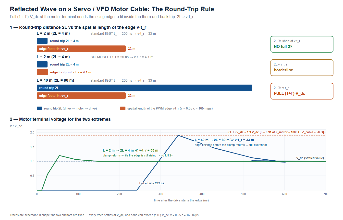
Every servo cable selection number here comes from one relation. The reflection coefficient at the motor interface is Gamma = (Z_motor - Z_cable) / (Z_motor + Z_cable), and the peak the winding sees is V_peak = V_dc x (1+Gamma). Read as a length budget instead of a voltage budget, the same relation gives the critical cable length, L_crit = (v x t_r) / 2: the wave travels out and back, so the round trip is 2L. If that is shorter than the spatial length of the edge, v x t_r, the reflection returns while the edge is still rising and the two overlap. If it is longer, the reflection arrives as a separate step and adds at full amplitude. One relation, read backwards — not a second formula.
On a 400 V class drive with a capacitor-filtered six-pulse front end the DC bus sits near the peak of the incoming line, about sqrt(2) x 400 V = 565 V. With a cable surge impedance of 50 ohm, the reflection coefficient is 0.78 for a 400 ohm motor, 0.91 for 1000 ohm and 0.97 for 3000 ohm, giving peaks of 1004 V, 1076 V and 1111 V against a ceiling of 1130 V. A 7.5 kW machine reaches 1.78x and a small servo motor 1.97x, because motor surge impedance is dominated by winding capacitance and falls as the machine grows. Motor power rating enters only through Z_motor.
Both terms come straight off a good VFD cable datasheet, and published values from an established shielded, XLPE-insulated family show how stable they are:
| Construction | Conductor | Characteristic impedance | Velocity of propagation | Effective v |
|---|---|---|---|---|
| 3 conductor + ground, foil + braid 85% | 16 AWG | 44 ohm | 55% | 165 m/us |
| 3 conductor + ground, foil + braid 85% | 10 AWG | 63 ohm | 55% | 165 m/us |
| 3 conductor + ground, foil + braid 85% | 6 AWG | 42 ohm | 55% | 165 m/us |
| 3 conductor, symmetrical segmented ground, dual copper tape | 3/0 AWG | 56 ohm | 55% | 165 m/us |
| 3 conductor, symmetrical segmented ground, dual copper tape | 250 MCM | 62 ohm | 55% | 165 m/us |
As published on the manufacturer’s product pages, e.g. this 300% ground flexible VFD cable. Typical, per manufacturer data sheet — use the figure for the exact construction you are buying.
Note that Z_cable does not fall neatly as the conductor grows — the 6 AWG part is lower than the 10 AWG part, because geometry and insulation wall matter more than copper area. Velocity of propagation lands on 55% of c, or 165 m/us, across the whole range; every number here uses that one constant.
An independent study of five constructions at a 36.5 m run, all #12 AWG: 87 ohm gave 1080 V at the motor terminals, 78 ohm 1110 V, two 58 ohm constructions 1150 V, and a 38 ohm shielded PVC cable 1260 V. The higher-impedance cable gave the lower peak, straight out of Gamma.
The Counter-Intuitive Part: A 2 m Servo Cable Is Not an Overvoltage Problem
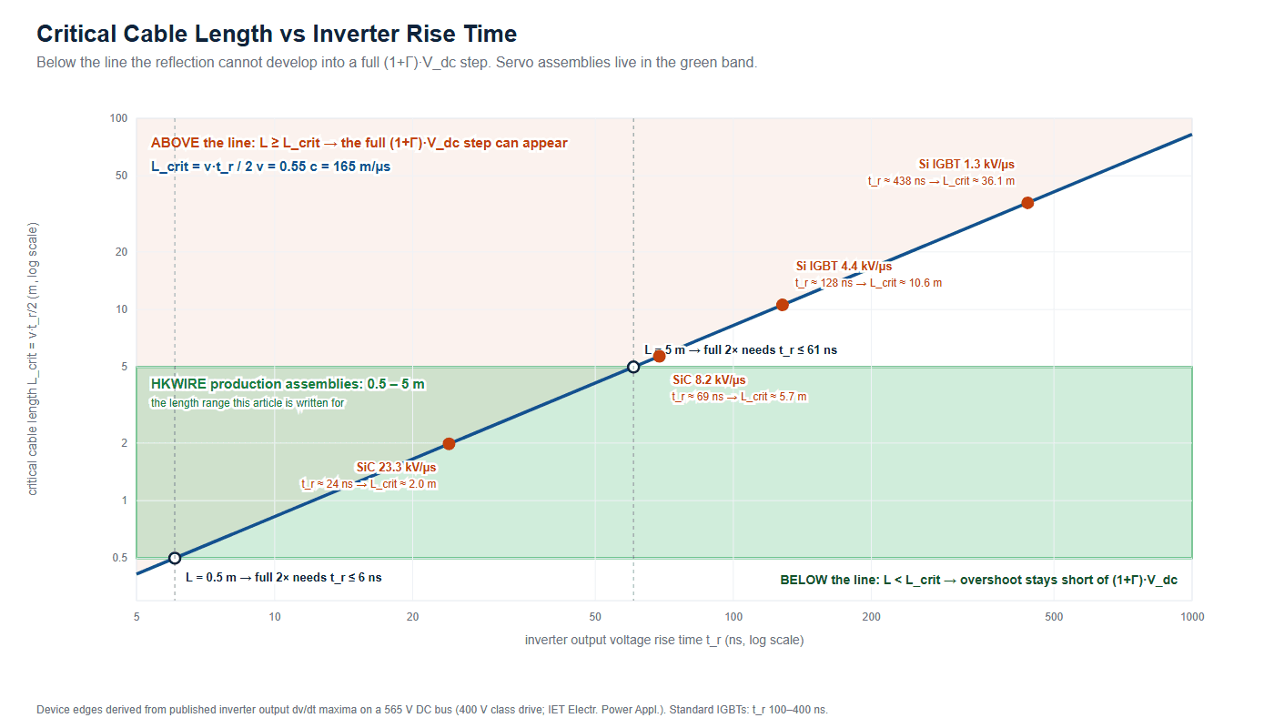
Now turn the servo cable selection question around. For a given assembly length, the slowest edge that can still produce a full doubling is t_r = (2 x L) / v. With v = 165 m/us:
| Assembly length | Round trip 2L | Edge would have to be faster than | What that means in practice |
|---|---|---|---|
| 0.5 m | 1.0 m | 6.1 ns | No inverter you can buy switches this fast |
| 1 m | 2 m | 12.1 ns | Still faster than any production drive |
| 2 m | 4 m | 24.2 ns | Only the fastest SiC modules |
| 3 m | 6 m | 36.4 ns | Very fast SiC with a small gate resistance |
| 5 m | 10 m | 60.6 ns | Fast SiC drives enter the picture |
| 8 m | 16 m | 97.0 ns | Fast IGBT territory |
| 15 m | 30 m | 181.8 ns | Standard IGBT territory |
| 30 m | 60 m | 363.6 ns | Every drive qualifies |
Compare those thresholds with real devices. Published inverter output dv/dt maxima for a 400 V class drive convert to an equivalent edge on the 565 V bus: 1.29 kV/us gives 438 ns and L_crit 36.1 m; 4.43 kV/us gives 128 ns and 10.5 m; 8.17 kV/us gives 69 ns and 5.7 m; 23.26 kV/us gives 24 ns and 2.0 m.
Put the two together and it is blunt. A 2 m assembly needs a drive edge faster than 24 ns before a full doubling can form on it. A standard IGBT drive — most installed servo and VFD hardware, with output edges of 100-400 ns — is 4 to 16 times slower. On a 0.5-5 m assembly with an IGBT drive, reflected-wave overvoltage is not your problem. You need roughly 10 m of cable with a fast IGBT, or a SiC drive with more than about 2 m.
When to worry about overvoltage, and when to worry about EMC
| Drive output edge | L_crit | 0.5-1 m | 1-2 m | 2-5 m | 5-15 m | 15-30 m | over 30 m |
|---|---|---|---|---|---|---|---|
| 438 ns (soft / high-power IGBT) | 36.1 m | none | none | none | none | borderline | full 2x |
| 128 ns (fast IGBT) | 10.5 m | none | none | borderline | full 2x | full 2x | full 2x |
| 69 ns (SiC) | 5.7 m | none | borderline | borderline | full 2x | full 2x | full 2x |
| 24 ns (fast SiC) | 2.0 m | borderline | full 2x | full 2x | full 2x | full 2x | full 2x |
“none” = no full doubling can form. “borderline” = within a factor of two of L_crit, so the peak depends on the exact edge shape. “full 2x” = the full (1+Gamma) x V_dc step can appear.
Read the 2-5 m column, where most servo assemblies live. It is “none” for both IGBT rows. A construction that spends budget on reflected-wave mitigation for a 2 m IGBT-fed axis spends it on nothing. That axis is fully exposed to bearing current and to radiated emission from the shield, which is what you should be specifying against.
L_crit from 33 m to 5.7 m, so a cable that was invisible at 10 m becomes a full doubling case. Verify against the specific drive model and its programd carrier frequency.Shielding: Coverage Percentage Is the Least Interesting Number
If reflected-wave mitigation is not what you are buying, shielding is — and this is where most of a servo cable selection budget belongs. The industry’s favorite specification, “85% coverage”, is the weakest lever you have. What describes a shield is its surface transfer impedance: the voltage induced on the inner conductors per unit shield current per unit length. The methods are one family. IEC 62153-4-3 covers surface transfer impedance by the triaxial method, the magnetic coupling term. IEC 62153-4-4 covers screening attenuation by the triaxial method, which matters when coupling is capacitive or aperture-dominated.
A single tinned copper braid at around 85% optical coverage typically lands in the tens of milliohms per meter at 100 MHz (typical, per manufacturer data sheet). Adding an aluminum-laminate foil under the braid takes that down by roughly a factor of three to five, because a foil has no apertures; double braid goes lower again. Below about 5 m of run, with a feedback cable in the same tray, foil plus braid beats braid alone every time.
Same 85% coverage, an order of magnitude apart
Optical coverage is a two-dimensional area ratio — the fraction of the cable surface covered by metal. It says nothing about the shape of the apertures left uncovered. A dense braid with many carriers and a shallow braid angle leaves many small apertures; a sparse braid with fewer carriers and a steep angle leaves fewer but longer ones. High-frequency leakage depends on aperture dimensions relative to wavelength, so the second construction can be several times worse at the identical coverage figure. Published transfer impedance data for commercial braids at 85% coverage spans roughly a fivefold range for exactly this reason, and the shield DC resistance plus contact resistance at the braid crossovers add a low-frequency term unrelated to coverage.
Then the termination swamps both. Compare the two paths on a 2 m assembly with a 50 milliohm per meter braid:
| Return path for shield current | What it contributes | At 1 MHz | At 10 MHz |
|---|---|---|---|
| The shield itself over 2 m (50 milliohm/m) | 0.1 ohm of coupling | 0.1 ohm | 0.1 ohm |
| A 100 mm pigtail drain wire (about 1 uH per meter of free conductor) | 100 nH of series inductance | 0.63 ohm | 6.3 ohm |
| 360 degree circumferential clamp | a fraction of a nanohenry | negligible | negligible |
At 1 MHz the pigtail is already six times the coupling impedance of the entire shield it terminates; at 10 MHz it is more than sixty times. Buying a better braid moves transfer impedance by a factor of three to five. Terminating the braid you already have at 360 degrees moves it by a factor of twenty or more, and costs a gland instead of a re-spec. Change the termination before you change the cable.
The specification follows: state the shield construction and minimum coverage, the drain arrangement, and if EMC is contractual, transfer impedance in milliohms per meter at a stated frequency with the test method named. A coverage percentage alone is not a testable EMC requirement. The same distinction shows up on shielded network runs — see M12 P-coded EtherCAT cable, M12 B-coded PROFIBUS cable and RJ45 versus M12 X-coded industrial Ethernet.
3+3 Symmetric vs 3+G, and Where the Feedback Pairs Go
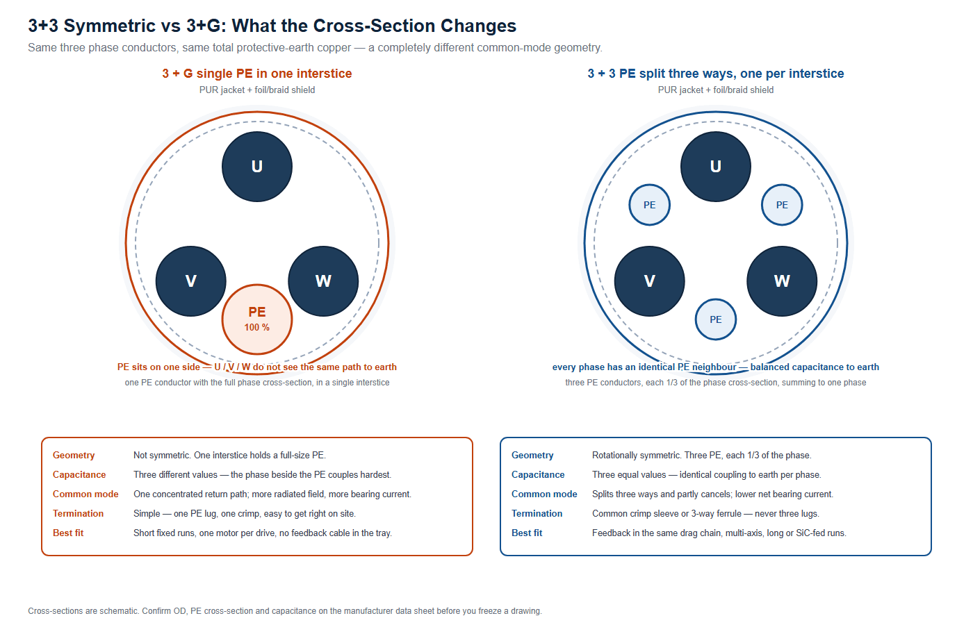
Shield construction decides how much noise leaves the cable. Conductor geometry decides where the common-mode current flows — the second half of a servo cable selection decision. In a plain 3+G cable a single protective earth conductor of full phase cross-section fills one interstice, so the three phases see three different distances to it and their capacitances differ; the common-mode current returns through one concentrated path on one side, which radiates more effectively and pushes more current through the motor shaft. In a 3+3 build the earth conductor is split into three equal parts, each one third of the phase cross-section, in the three interstices. Total earth copper is unchanged, every phase has an identical neighbour geometry, and the common-mode current splits into three paths that partly cancel.
| Property | 3+G (single full-size PE) | 3+3 (three PE, each 1/3) |
|---|---|---|
| Total protective earth cross-section | One phase equivalent | One phase equivalent |
| Geometric symmetry | None; one interstice filled, two not | Rotational, 120 degrees |
| Capacitance to earth per phase | Three different values | Three equal values |
| Common-mode return path | Single, concentrated | Three, partly cancelling |
| Radiated emission at equal length | Higher | Lower |
| Termination work | One PE lug, hard to get wrong | Common crimp sleeve or 3-way ferrule |
| Best fit | Short fixed runs, one axis, no feedback nearby | Drag chains, multi-axis, long runs, fast-edge drives |
Termination is where 3+3 gets abandoned in the field, and it should not be. Three separate lugs on three one-third PE conductors defeats the point, because the return current no longer shares a common low-impedance bond. Crimp all three into one sleeve, then land one lug. The same applies inside a molded assembly: if the earth ring does not bond all three, the symmetry you paid for is gone inside the overmold.
Encoder, resolver and brake conductors
- Encoder: a digital differential link. Every signal pair must be twisted and individually shielded, with pair impedance held constant to the connector. Overall shielding is not a substitute for per-pair shielding.
- Resolver: two analog sine and cosine pairs at low amplitude. Amplitude accuracy is the measurement, so this is the most noise-sensitive conductor in the assembly. It needs its own foil shield and its own reference pair, and must not share a shield with the brake.
- Brake: a switched 24 V DC load, so a noise source rather than a victim. Put it in the power group, never the feedback group, and give it its own shielded pair on long assemblies.
On routing, the rule that survives contact with real machines is separation plus a controlled crossing angle: keep power and feedback runs apart, cross at 90 degrees when they must, and never run a feedback cable parallel to a motor cable for any distance. That is why a molded composite assembly with an internal divider beats two loose cables zip-tied together — the geometry is fixed by the mold rather than by whoever closed the cabinet. Our M23 screw lock cable for servo motor power and encoder feedback and the M12 M-coded motor cable with integrated brake conductors are built this way, and the cobot arm drag-chain harness takes it into continuous flex.
Jacket, Termination and Selection by Drive Class
Specify the test, not the adjective. Oil resistance is measured by immersion in IRM 902 or IRM 903 reference oils fixed by ASTM D5964, using the method in IEC 60811-404, with a common acceptance criterion of at least 50% tensile and elongation retention after 96 h at 100 degrees C. Drag-chain life has no universal cycle-count standard — ask for the supplier’s bench curve, generated by DIN EN 50396 clause 6.2 and 6.3. Do not accept a blanket “10 to 15 times the outer diameter” rule; real chain-rated constructions range from about 5 to 8.5 times the diameter. Datasheets commonly quote -40 to +90 degrees C, and polyester-type PUR hydrolyzes in hot humid conditions, so specify a polyether grade for washdown work.
On termination, bond the shield at both ends, circumferentially, with a metal gland or clamp. Bonding at one end leaves the other floating, which turns the shield into a capacitively coupled antenna and is the most common cause of an axis that passes on the bench and fails on the machine. The drive end matters most for emissions; the motor end matters most for giving common-mode current a short return path instead of one through the bearings. Background: PVC versus PUR versus TPE cable jacket, oil-resistant cable material selection, continuous-flex drag chain cable selection, bend radius and pull force routing and halogen-free oil-resistant UV cable jacket.
Pulling it together, the servo cable selection table below tiers the decision by drive class and run length:
| Drive class and run | Dominant risk | Reflected-wave action | Shielding action | Geometry action |
|---|---|---|---|---|
| Servo under 1 kW, 0.5-3 m | Encoder noise from the adjacent power bundle | None required | Foil + braid over power; individually shielded feedback pairs | 3+3 if the feedback cable shares the chain |
| Servo or VFD 1.5-7.5 kW, 0.5-5 m | Bearing current and radiated emission | None required | Braid 85% minimum plus foil, 360 degree bond both ends | 3+3 preferred, single PE acceptable |
| VFD 11-30 kW, 5-30 m | Reflected wave approaching L_crit with fast IGBTs | Check the drive datasheet maximum cable length; add a dv/dt reactor if exceeded | Foil + braid, low-capacitance insulation | 3+3 symmetric |
| VFD 37-75 kW, up to 50 m | Reflected wave and bearing current together | Reactor or dv/dt filter as standard practice | Foil + braid, full 360 degree gland both ends | 3+3 or symmetric segmented ground |
| Any SiC-fed axis, 2-5 m | Reflected wave, plus much faster common-mode transients | Run the L_crit check before anything else | Foil + braid minimum; expect higher emission above 1 MHz | 3+3 effectively mandatory |
Conductor cross-section is an ampacity and voltage-drop question, not an EMC question — see voltage drop and ampacity cable sizing. An undersized motor cable that meets every shielding requirement still overheats. Ingress requirements are separate again; IP67 versus IP68 versus IP69K covers what each rating actually tests, and a washdown axis typically lands on a part like the M12 IP69K washdown cable.
What to Put on the Drawing and in the Purchase Order
Most servo cable selection arguments are really specification arguments. A supplier cannot meet a requirement you did not write down, and “shielded VFD cable” is not a requirement. Put these on the drawing:
- Electrical: rated voltage; conductor cross-section and stranding class per IEC 60228; counts of power, feedback and brake conductors.
- Transmission line and shield: nominal characteristic impedance and velocity of propagation from the construction you are buying; shield construction, minimum optical coverage, drain arrangement, and where EMC is contractual, surface transfer impedance at a stated frequency by the triaxial method of IEC 62153-4-3.
- Geometry: 3+3 or 3+G, the protective earth cross-section, and how the PE conductors are combined at the connector.
- Feedback group: pair count, per-pair shielding, twisting pitch class, and an explicit statement that brake conductors are excluded from the feedback bundle.
- Jacket and flex: material, temperature class, reference oil and retention criterion, and the flex cycle count and bend radius you actually need.
- Tests to report: shield continuity end to end, transfer impedance where specified, dielectric withstand, conductor resistance, and capacitance to conductor and shield.
Two standards are frequently confused. IEC 61800-3 is the EMC product standard for adjustable speed power drive systems, the document the drive’s own EMC claim is made against — your cable must be compatible with that claim, not replace it. IEC TS 60034-25 is the application guide for AC machines on converter supplies; its shaft-current clause backs the bearing-current discussion above. Interface voltage definitions are in IEC TS 61800-8, drive ratings in IEC 61800-2, and single-wire flame propagation in IEC 60332-1-2 — which, on one cable, says nothing about a bundle.
Our wire harness drawing checklist for OEM buyers turns that list into a document, and the custom cable assembly RFQ guide gathers the electrical, mechanical and environmental inputs in one pass. For molded connectors see overmolded cable design and how to specify an overmolded cable assembly, with tooling implications at mold making and tooling and overmolding and injection. Connector-side choices are in the M12 connector coding guide and connector locking mechanism selection.
FAQ
How long can a servo motor cable be before reflected-wave overvoltage is a real risk?
It depends on the drive’s output edge, not the cable. A standard IGBT drive at 100-400 ns gives a critical length of roughly 8 to 33 m, so almost no real assembly is at risk. A SiC drive at 25-70 ns drops that to about 2 to 6 m, and a 5 m axis is exposed. Run the servo cable selection check as L_crit = (v x t_r) / 2 before assuming either answer.
Is a higher or lower cable characteristic impedance better for overvoltage?
Higher, counter-intuitively. Gamma shrinks as Z_cable moves up toward the motor surge impedance, so the peak falls. In one published study at 36.5 m, an 87 ohm cable measured 1080 V at the motor and a 38 ohm cable 1260 V. Cable impedance is not a quality ranking; it is a mismatch parameter.
What does 85% shield coverage actually guarantee?
That 85% of the cable surface is covered by braid metal — nothing about transfer impedance. At equal coverage a dense braid leaves many small apertures and a sparse one leaves fewer but longer apertures, and high-frequency leakage depends on aperture size. Published data at identical coverage spans roughly a fivefold range. If EMC is contractual, specify transfer impedance at a stated frequency and name the test method.
Should the shield be bonded at both ends or only at the drive end?
Both ends, circumferentially. A 100 mm pigtail drain is about 100 nH — roughly 0.63 ohm at 1 MHz and 6.3 ohm at 10 MHz, six to sixty times the coupling impedance of a 2 m shield at 50 milliohms per meter. Bonding at one end leaves the other floating and turns the shield into a capacitively coupled antenna. A 360 degree clamp buys more than any braid upgrade.
Do I need a 3+3 symmetric cable or is 3+G enough?
3+G is enough for short fixed runs on a single axis with no feedback cable in the same tray. 3+3 wins as soon as any of those breaks: a drag chain, multiple axes, runs over about 5 m, a fast-edge drive, or a feedback cable sharing the route. Total earth copper is identical, so the difference is construction and termination work.
Can the encoder cable share a drag chain with the motor cable?
Yes, and in a molded composite assembly that is usually right, provided the feedback pairs are individually shielded, the brake conductors stay in the power group, and the internal geometry is fixed by the mold rather than by the installer. The failure mode to avoid is two separate cables zip-tied together, which lets the relative position change as the chain moves.
Why does the same servo cable selection work on one machine and fail on another?
Because the cable is rarely the variable. The differences are almost always the drive’s switching edge, the run length, the carrier frequency setting, and how the shield is terminated. A shorter edge from a newer drive can move the critical length from 33 m to 6 m without anyone touching the cable. Check termination first, then drive settings, then the construction.
Send us the drive data, not just the cable length
HKWIRE builds custom servo and VFD motor cable assemblies from 0.5 to 5 m with 3+3 symmetric power cores, individually shielded encoder, resolver and brake groups, foil plus braid shielding and 360 degree terminations, in PUR or TPE jackets for oil and drag chain duty. Tell us the drive model, run length and feedback protocol, and we will tell you which problem you have.
Pick the wrong lever and the axis still runs — until the first bearing failure or the first EMC test. Length decides whether you have a reflected-wave problem; everything else is shielding, geometry and termination, which is where a servo cable selection process should spend its budget. HKWIRE builds these assemblies to drawing. Browse the M8 and M12 circular cable and custom wire harness ranges, or start from a build such as the M12 K-coded 630 V AC motor cable, M12 drag chain cable, M12 12-pin encoder cable or hybrid robot torsion cable. High-voltage DC assemblies follow identical discipline — see the EV high voltage harness and energy storage cabinet wiring harness.







