

Why exit direction is a real decision, not a cosmetic one
Exit direction is usually the last line filled in on a cable drawing, and it is often copied from the previous project without discussion. On the bench it decides five things that are expensive to discover late: how much clear depth your enclosure needs behind the panel, how tightly the cable must bend in its first few centimeters, which way the pull force lands on the strain relief, whether the rear seal stays compressed after a thousand mating cycles, and whether a technician can actually get a hand on the connector to unplug it. All five hinge on one early choice: a straight exit or a right-angle cable connector.
A straight exit is the default for a reason. It is cheaper to tool, easier to overmold, and puts the cable in line with the contact axis so the pull force runs straight through the strain relief. A right-angle cable connector solves a different problem: it trades some of that mechanical simplicity for a much shallower footprint behind the mating face.
The mistake is treating the choice as a matter of taste. It is a mechanical decision with consequences you can predict.
This guide is written for people who have a real enclosure in front of them. It covers the geometry behind the decision, the nine trade-offs that actually separate the two options, twelve application scenarios with their specific installation characteristics, the installation details that separate a clean build from a service call, and a specification checklist you can paste into a drawing.
Part 1 — What “right-angle” actually covers
Before comparing, separate the variants that get lumped together under one name. They are not interchangeable, and picking the wrong one is a common cause of a harness that fits the drawing but not the machine.
The angle variants
- 90 degree exit. The cable leaves perpendicular to the mating axis. This is what most people mean by a right-angle cable connector, and it gives the largest depth saving.
- 45 degree exit. A shallower turn, useful when 90 degrees puts the cable hard against the panel but straight does not fit. It keeps part of the straight exit’s mechanical advantage, because the pull force is only partly off-axis.
- 270 degree, or reversed exit. The cable turns back past the mating face and runs alongside the body. Rare, and worth a supplier conversation because it changes the strain relief design entirely.
- Low-profile or pancake exit. A flattened body with the cable leaving at 90 degrees within 8 to 10 mm of the mating face. Used on guitar pedalboards and equipment mounted flush against a wall. Saves the most space, tolerates the least abuse.
- Rotatable or adjustable exit. A collar lets the cable be aimed at one of several positions — commonly four or eight — after assembly. Costs more and adds a sealing surface, but removes the risk of specifying the wrong direction.
The distinction that matters most
The turn can happen inside the connector body, where the contacts are routed and the overmold captures the cable at 90 degrees, or in the cable immediately after a straight connector, where you buy a straight connector and bend the cable yourself.
The second is not a right-angle connector. It is a straight connector being asked to do a job it was not designed for, and it is where most field failures start.
Here is why, in mechanical terms. A strain relief works by gripping the cable jacket over a length of molded material and transferring load from the jacket into the connector shell. Inside that gripped length, the cable cannot bend — that is the point. Immediately beyond it, the cable is free. If you take a straight overmolded assembly and bend the cable by hand right where the relief ends, you create a bend at the exact boundary between a rigidly held section and a free section. Every flex cycle concentrates there. The jacket is unsupported, the conductors inside have no bend-limiting structure, and the shield braid, if there is one, kinks and opens up at the fold.
Two things follow from this. First, the failure is not at the connector, so swapping the connector will not fix it. Second, the failure is slow: the conductors work-harden over hundreds or thousands of cycles and then break, usually intermittently first. That is why this mistake is so often diagnosed as a bad connector or a bad crimp.
The correct fix for “I need the cable to turn here” is a body that was molded to turn. If you cannot get one, the next best thing is a bend-limiting sleeve or a service loop that keeps the bend well outside the strain relief, and even then you are managing the problem rather than solving it.
Do not solve it with a 90 degree adapter. An adapter that plugs into a straight connector and turns the cable adds a second mating interface, which is another contact set to wear and another place for a seal to fail. Worse, it creates a longer and more rigid lever than either a straight or a purpose-built right-angle cable connector assembly, so the moment applied to the device socket goes up rather than down. An adapter is a useful thing to keep in a toolbox for a one-off fit check. It is not a production solution.
Everything below assumes the turn is captured inside a molded body.
Part 2 — The geometry: how much depth does each option actually need?
This is where the decision usually gets made, so it is worth doing the arithmetic properly instead of guessing.
Where the depth goes on a straight exit
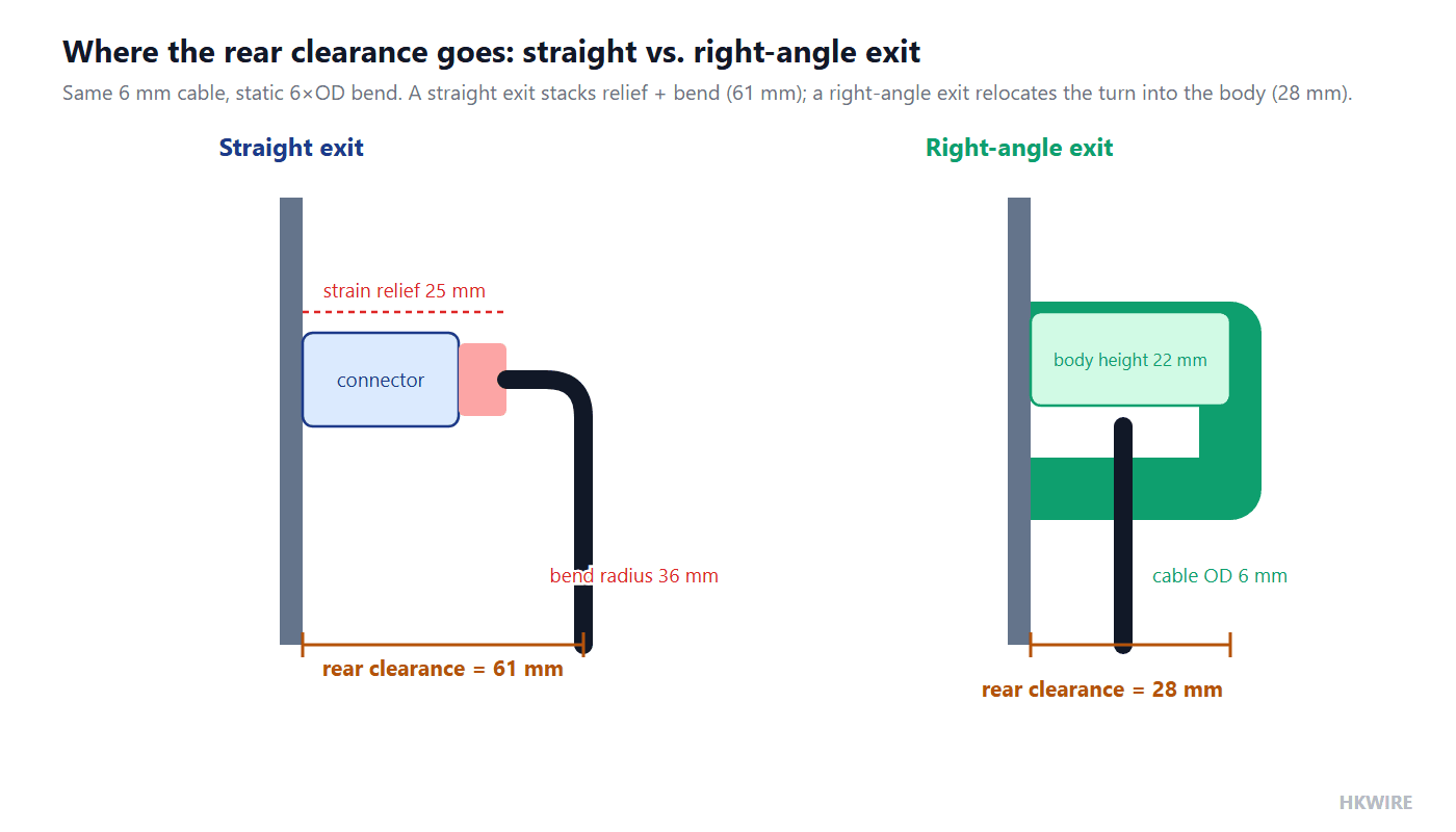
A straight overmolded assembly needs clear space behind the connector for two things in series: the strain relief, and then the bend.
The relief is typically 15 to 35 mm depending on cable diameter. The bend is governed by the cable’s minimum bend radius. For static installations a common rule is 6 to 8 times the cable’s outer diameter; for anything that moves, 10 to 12 times. So the total rear clearance before the cable can run parallel to the panel is:
Rear clearance (straight) = strain relief length + minimum bend radius
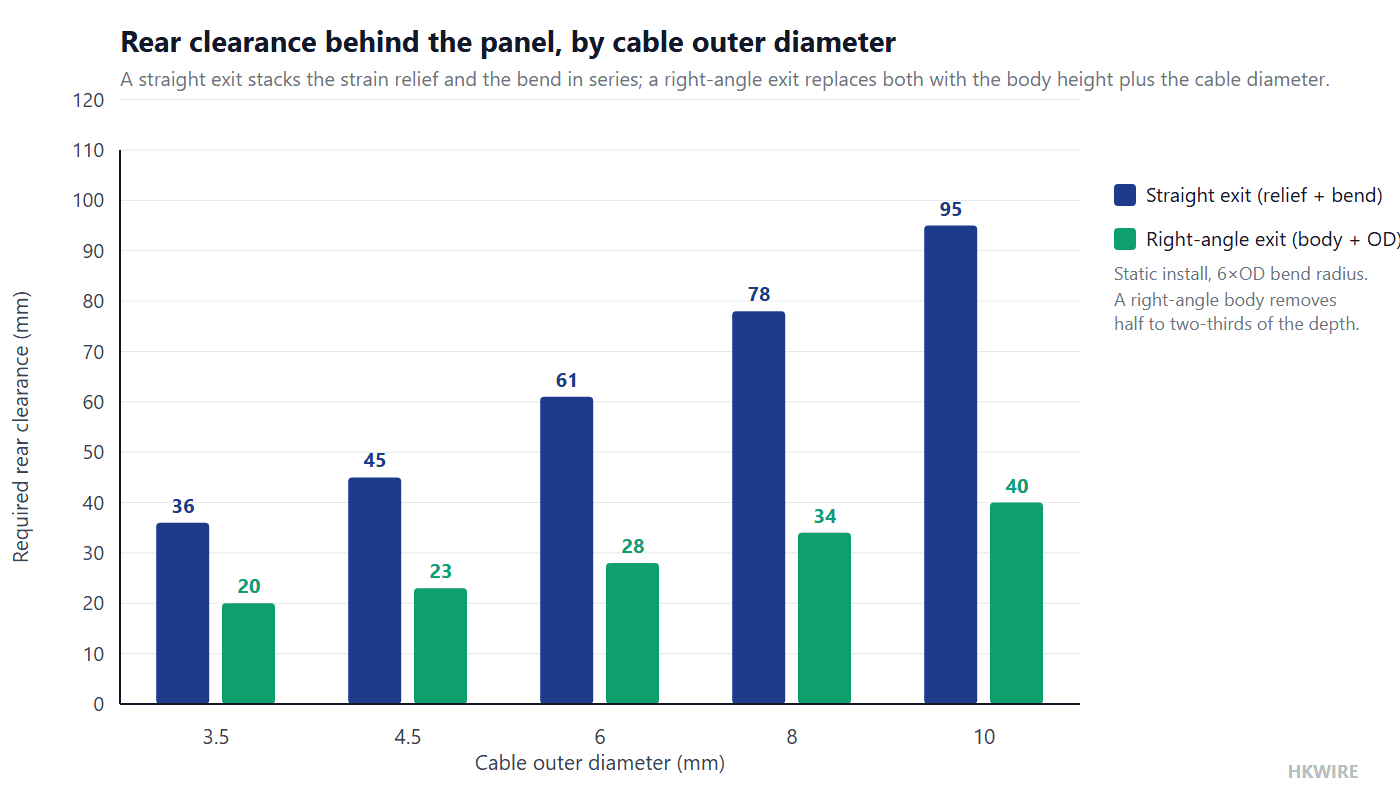
The table below uses 6× outer diameter for static use and 10× for dynamic, plus a realistic relief length.
| Cable OD | Relief length | Min bend radius (static, 6×OD) | Total rear clearance, straight | Right-angle body height + OD | Depth saved |
|---|---|---|---|---|---|
| 3.5 mm | 15 mm | 21 mm | 36 mm | 16 + 3.5 = 20 mm | 16 mm |
| 4.5 mm | 18 mm | 27 mm | 45 mm | 18 + 4.5 = 23 mm | 22 mm |
| 6.0 mm | 25 mm | 36 mm | 61 mm | 22 + 6 = 28 mm | 33 mm |
| 8.0 mm | 30 mm | 48 mm | 78 mm | 26 + 8 = 34 mm | 44 mm |
| 10.0 mm | 35 mm | 60 mm | 95 mm | 30 + 10 = 40 mm | 55 mm |
For moving applications the numbers on the straight side roughly double, because the bend radius rule goes from 6× to 10×:
| Cable OD | Min bend radius (dynamic, 10×OD) | Total rear clearance, straight | Depth saved by a right-angle body |
|---|---|---|---|
| 6.0 mm | 60 mm | 90 mm | 62 mm |
| 8.0 mm | 80 mm | 115 mm | 81 mm |
| 10.0 mm | 100 mm | 140 mm | 100 mm |
Two observations from these tables.
First, the absolute saving grows with cable diameter, but the *proportional* saving is roughly constant — a right-angle body removes about half to two-thirds of the rear clearance. That means the smaller the enclosure, the more likely the right angle is the only option, and the larger the cable, the more dramatic the saving.
Second, note that a right-angle body does not remove the bend radius requirement. It moves the bend inside the mold, where the mold designer has to respect it. If your cable is 10 mm OD and the application moves, you still need 100 mm of bend somewhere — you have just relocated where it starts. This is the most common misunderstanding about right-angle cable connectors, and it is why they are sometimes specified to solve a problem they cannot solve.
How to measure the depth you actually have
Do this before specifying anything, because the number people quote from a datasheet is rarely the number available in the built machine.
- Measure from the outer face of the panel to the nearest obstruction behind it — a wall, a DIN rail, another connector, the inside of the enclosure back.
- Subtract the thickness of the panel itself if your measurement started at the outer face and the connector seats through it.
- Subtract any clearance the door or cover needs when it closes. A lid that closes over the connector usually needs 5 to 10 mm more than the connector alone.
- Subtract the mating half’s rear protrusion, if the receptacle is a bulkhead type that extends backward.
- What remains is your budget. Compare it against the table above.
If the remaining budget is under about 40 mm, a straight exit is almost certainly off the table for any cable above 4 mm OD. Between 40 and 80 mm it depends on the cable. Above 80 mm, a straight exit will usually fit and you should choose on other grounds.
Our guide to panel mount connector selection walks through the rear clearance calculation in more detail, including threaded versus bayonet versus push-pull rear protrusion.
Part 3 — Nine trade-offs that decide it
1. Depth behind the panel
Covered above. The short version: a right-angle exit collapses the rear clearance from “bend radius plus relief” to “body height plus cable diameter,” typically halving it. On a shallow enclosure this is the entire decision.
2. Bend radius and the first 50 mm
Bend radius rules do not stop at the connector. The first 50 mm of cable is where stress concentrates, because that section carries every bit of handling, routing and vibration, and it is the section restrained by the strain relief.
A straight exit gives the cable a natural line. If the run continues along the contact axis, there is no bend at all. A right-angle exit introduces a permanent turn that has to be held at or above the cable’s minimum radius, which means the mold must be designed for it rather than improvised.
There is a counterweight here, and it is the reason right-angle bodies genuinely help in tight installations rather than merely trading one problem for another. If the cable has to turn anyway — because the run goes sideways along a panel — then a straight exit forces that turn to happen in free cable, right at the end of the strain relief, at whatever radius the installer happens to produce. A right-angle body takes the same turn and holds it at a radius the mold designer controlled. In that comparison the right angle does not add a bend; it removes an uncontrolled one.
So the honest statement of trade-off 2 is not “right angle is worse for bend radius.” It is: a right angle makes the bend controlled and fixed; a straight exit makes it variable and installer-dependent. Where the run is genuinely straight, straight wins. Where the run has to turn within the first 50 mm, the molded angle usually wins.
The practical rule: for static installations hold 6 to 8 times the cable diameter at the exit; for anything that moves, 10 to 12 times. And be aware that a right-angle exit in a moving application puts the turn inside the stiffest, least forgiving part of the assembly — which is exactly why continuous-flex applications are the one place a straight exit is nearly always correct.
Our article on bend radius, pull force and routing covers the calculation, and if the application involves continuous motion read the drag chain cable selection guide before committing to any molded angle, and for published flex-life figures see the igus chainflex guarantee.
3. Strain relief and pull direction — the moment arm problem
This is the trade-off most often skipped, and it is the one that produces cracked solder joints.
Strain relief works best when the pull force runs along the axis the relief was molded to resist. A straight exit aligns perfectly: pull the cable and the load runs in pure tension through the relief, into the shell, and out through the panel. A right-angle exit means a pull on the cable applies a bending moment to the molded body, because the force acts at a distance from the shell.
The moment is simply force times distance, and the distance is the body height plus part of the relief length — call it 25 to 40 mm for a typical M12 or USB-C right-angle body. A 50 N tug, which is roughly what a snagged cable delivers, becomes 50 × 0.030 = 1.5 N·m applied to the point where the overmold meets the shell. That is a lot for a small plastic boss.
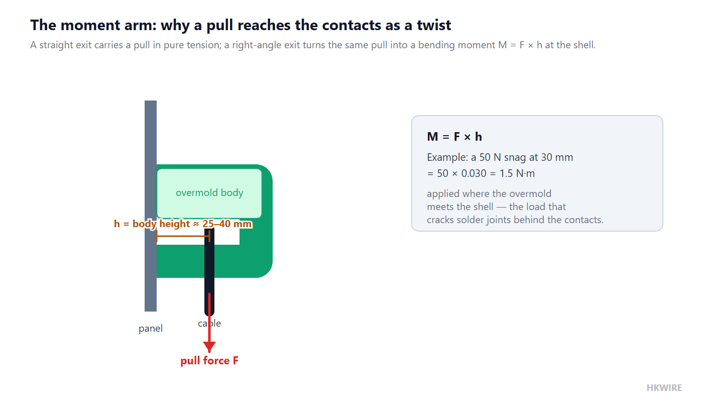
Good right-angle molds handle this three ways: they extend the strain relief so the load is spread over more jacket length, they key the overmold to the connector shell so load transfers into metal rather than into the contacts, and they use a shell material and wall thickness sized for the moment. Cheap ones do none of these, and the failure mode is familiar: the cable is fine, the mold is fine, and the solder joints behind the contacts have cracked.
If the assembly will be pulled, snagged or carried by its cable, specify a right-angle body with an extended relief and ask the supplier what pull force it is tested to. This is also where the locking mechanism interacts with geometry: a screw-lock shell gives the overmold a much better load path into the panel than a friction-fit latch, because the threaded coupling carries load into the receptacle rather than leaving it in the mold.
4. Signal integrity at high speed
For power, sensor signals and most fieldbus traffic, exit direction has no meaningful electrical effect. Above roughly 1 Gbps it is worth a second thought, but the reason is usually misunderstood.
The turn itself is not the problem. A 90 degree transition inside a well-designed molded body, with the pairs held in position and the shield continued through, is electrically unremarkable. A right-angle RJ45 that is properly built will pass the same channel tests as a straight one.
The problems come from what happens around the turn:
- Pairs that untwist as the cable is routed. The lay length is what cancels crosstalk. If the mold lets pairs splay where they enter the body, that section behaves like untwisted wire.
- A shield that is terminated on one side of the bend but not carried through. Any gap in the shield is an aperture, and at gigabit speeds it matters.
- A drain wire that ends up longer on one side. This is a classic right-angle cable connector assembly defect, because the turn makes one side of the cable geometrically longer than the other and a drain wire cut for a straight body ends up stretched or slack.
- Impedance discontinuity at the transition. A sharp change in the relationship between conductors and shield changes impedance locally. Good designs keep the transition gradual relative to the wavelength involved.
For gigabit and above, the specification to write down is not “right-angle” but “shield continuity through the exit, 360 degree termination, pair lay maintained to within X mm of the contacts, channel tested to the relevant category.” If you are choosing between connector families, RJ45 versus M12 X-coded and Category 5e, 6 and 6A cover the bandwidth side, single pair versus four-pair Ethernet covers the emerging low-wire-count option, and shielded versus unshielded cable covers whether you need the shield at all. Note that shielding is not automatically better — that article goes into the cases where a shield makes EMC worse.
5. Sealing and IP rating
This is where right-angle designs get into trouble, and it is the least obvious of the nine.
An ingress rating is achieved by a sealed system with three sealing points: a face seal at the panel, a seal between the connector halves when mated, and a seal where the cable leaves the body. The first two are unaffected by exit direction. The third is not.
A straight cable exit is the easiest geometry to seal, because a round cable passes through a round gland and the compression is uniform all the way around. A right-angle exit puts the cable through a body that must both turn and seal, and the mold has to compress evenly around a cable that is changing direction inside it. On the inside of the turn the seal is compressed more; on the outside, less. Get that wrong and one side of the annulus is under-compressed.
It is very doable. It is also the place where a marginal mold shows up as a leak at 12 months rather than at final test, because the failure is slow compression set rather than a visible gap.
Three practical points:
- State the rating you need in terms of the mated assembly, not the connector body alone.
- Ask whether the rating was tested on the right-angle body specifically, or inherited from the straight version of the same family.
- If the environment is genuinely hostile, understand how water actually gets into a sealed assembly before you specify, because the leak path is frequently not the one people assume — capillary travel along the conductors, and pressure cycling that pumps moisture past a seal that would hold static water.
Our IP67, IP68 and IP69K comparison defines what each tier actually tests, and waterproof cable assembly leak paths covers how sealed assemblies fail in service. IEC 60529 defines the IP code for the general case and ISO 20653 defines IP69K for road vehicles.
6. Assembly and service access
The sixth trade-off is human. A right-angle connector is harder to grip when mating, because the cable occupies the space your fingers would use. In dense panels this compounds: eight right-angle cable connectors side by side means eight cables crossing each other’s access space, and the technician ends up mating the middle ones by feel.
This cuts both ways, though. Right-angle exits can make service *easier* when they keep cables out of a door swing, off a hinge, or away from a removable cover. A cabinet where every cable exits sideways along the wall is easier to work in than one where eight cables stand 80 mm off the back plane waiting to be caught by the door.
Three mitigations:
- Specify the exit direction per position so cables fan outward instead of across each other. This costs nothing on the drawing and saves real time in the field.
- Consider rotatable bodies on the positions serviced most often, or where routing is not finalized at order time.
- Check the pitch. If two right-angle cable connectors sit side by side, confirm the bodies do not collide once both cables are dressed. This is a real constraint on M12 distribution boxes and multi-port panels.
7. Vibration and shock
A right-angle body puts mass at the end of a lever. Compared with a straight exit, the center of mass of the overmold sits farther from the panel, which lowers the resonant frequency of the connector-cable system and increases the bending stress at the panel interface under vibration.
In practice this matters when:
- The connector is mounted on a vibrating surface — a motor housing, a pump skid, a vehicle panel.
- The cable is unsupported for a long distance after the exit, letting it whip.
- The assembly is small and light, so the added overmold mass is a meaningful fraction of the total.
The fix is usually not to abandon the right angle but to add a cable clamp within 100 to 150 mm of the exit, which moves the resonant frequency up and stops the whip. If you cannot add a clamp, and the vibration is real, a straight exit with a clamped service loop is the safer design.
For servo and drive applications where the cable also carries high dv/dt noise, the servo cable selection guide covers the shielding side of the same problem.
8. Heat, airflow and what the cable blocks
Rarely considered, occasionally decisive.
A right-angle exit routes the cable flat against the panel or along the enclosure wall. In a sealed cabinet that relies on convection, a bundle of cables dressed along a vent path reduces airflow. More directly, a cable pressed against a hot surface — a power supply case, a drivesink, a hydraulic manifold — sees a higher ambient temperature than the one in the datasheet, and conductor ampacity has to be derated for it.
There is a second effect: the right-angle body itself sits closer to the panel, so it is closer to whatever heat the panel is carrying. A connector rated for 85 °C ambient is fine on a cool panel and marginal on one running at 70 °C.
If the assembly carries meaningful current, size it against the actual local temperature. Voltage drop and ampacity covers the derating arithmetic.
9. Cost, tooling and lead time
Straight molds are simpler. They have fewer slides, they are easier to fill, and they generally run faster. On a 10,000 piece order the per-unit difference is real, and on a custom overmold the tooling difference is larger still.
What a right-angle body adds:
- Tooling complexity. The mold has to form the turn and usually needs additional slides or a split cavity.
- Cycle time. Slightly longer, and more sensitive to process variation.
- Validation. If you need a rating, the right-angle geometry needs its own test, not a borrowed one.
- Risk of a wrong-direction build. If the exit direction is wrong, the parts are scrap. This is the single biggest financial risk in specifying right-angle assemblies, and it is why rotatable bodies and clear drawing callouts pay for themselves.
Rotatable bodies add a further step: a collar, a second sealing surface, and an extra assembly operation.
Part 4 — Fourteen application scenarios and their installation characteristics
This is where the general trade-offs meet a specific machine. Each scenario below states the space constraint, what goes wrong with a straight exit, and the installation details specific to that case.
1. Industrial sensors and actuators on machine frames (M8 / M12)
The constraint. A proximity sensor or a valve block sits on a machine frame with 20 to 40 mm between the sensor body and the frame, a guard, or an adjacent actuator. The connector is at the back of the sensor, pointing into that gap.
What fails with a straight exit. The cable has to stand off 40 to 60 mm before it can turn. In practice it gets folded back on itself, the fold sits at the strain relief boundary, and the sensor starts intermittent-faulting after a few months of machine vibration.
Installation characteristics. Right-angle M8 and M12 cordsets are the standard answer and are widely stocked in both straight and angled versions for exactly this reason. Details that matter:
- Clocking. M12 right-angle bodies are commonly offered in fixed positions. Confirm which way the cable needs to leave before ordering, because the same part number in a different clock position is a different part.
- Purge and weld-slag zones. In food and welding environments the cable should exit downward so debris does not settle on the coupling. That is an exit-direction decision, not a connector decision.
- Shielding. Right-angle shielded M12 assemblies for encoder and servo feedback need the shield carried through the turn. Ask how it is terminated.
- A-coded versus other codings. Coding prevents mating the wrong connector, which matters when several right-angle cordsets are dressed into the same trunk. Our M12 connector coding guide covers A through T codes.
2. Control cabinets, PLC racks and DIN rail I/O
The constraint. I/O modules on a DIN rail, with 60 to 100 mm between the module face and the cabinet back, and usually a wire duct immediately below or above the rail.
What fails with a straight exit. Not usually a hard failure — more often a routing problem. Straight exits stand off into the duct space, the duct cover will not close, or the cables have to be folded down into the duct at too tight a radius for the wire gauge.
Installation characteristics. This is the scenario where exit direction should be specified per position, not per harness. A row of eight modules might want: positions 1 to 3 exiting down into the lower duct, position 4 exiting up because the lower duct is full, and so on. Drawing that out costs an hour and saves a rework cycle.
Also worth specifying: the cable length from the exit to the duct entry, so the dressing is repeatable, and whether the assembly needs a ferrule or a label at the module end.
3. Robotics, cobot arms and moving joints
The constraint. The cable must run along the arm, not stand off it. At a joint, a straight exit would put a stiff 80 mm stub into the path of the moving link.
What fails with a straight exit. The stub gets crushed by the link, or the bend radius is violated at every cycle of the joint.
Installation characteristics. This is the one scenario where the obvious answer is often the wrong one.
A right-angle exit at the joint looks correct and frequently is not the best solution, because the joint is a *moving* application and a molded turn is the stiffest thing you can put there. The usual better answer is a straight exit plus a proper cable guide or a strain-relief bracket that holds the cable on the arm’s natural bend path, with the bend happening in the cable where it can flex, not in a mold where it cannot.
Use a right-angle body at the joint only if the cable after the joint is essentially static — for example at a tool changer where the run from the joint to the tool is fixed. Otherwise, use a straight exit and manage the bend with hardware.
Read the drag chain selection guide before specifying anything for a moving joint.
4. Server racks, network cabinets and patch panels (RJ45)
The constraint. A patch panel in a shallow wall-mount cabinet — often 60 to 100 mm of usable depth behind the panel — or a switch installed against a wall.
What fails with a straight exit. Cat6A cable is stiff, around 6 to 7 mm OD, and a straight boot plus bend needs 60 to 90 mm. In a 100 mm cabinet there is nothing left. The usual outcome is cables folded hard against the cabinet door, which both violates bend radius and blocks the door.
Installation characteristics.
- Right-angle RJ45 is a mature product category and works well, but check two things: whether the latch is accessible once installed (some right-angle bodies bury it), and whether the boot is field-replaceable.
- Screw-lock right-angle RJ45 bodies exist for industrial and vibration-prone installations. If the cabinet is on a vehicle or a machine, the screw-lock versus latch comparison applies here directly.
- Shielded right-angle plugs need the drain wire handled correctly through the turn, as described in trade-off 4.
- Order the category you actually need. Cat6A is stiffer and larger than Cat6, and in a shallow cabinet that difference decides whether a straight exit fits at all. See Cat5e vs Cat6 vs Cat6A.
5. Broadcast, studio racks and OB vans (SDI / BNC, DMX)
The constraint. Patch bays and equipment racks where dozens of coaxial connections sit side by side, often at the rear of a rack with a door or a wall immediately behind.
What fails with a straight exit. Coax has a strict minimum bend radius — kinking it changes impedance and shows up as a return loss problem. In a shallow rack, a straight BNC forces a kink.
Installation characteristics. Right-angle BNC and right-angle DMX connectors are standard in this industry for precisely this reason. Details that matter:
- Return loss, not just continuity. A right-angle coax connector must maintain 75 ohm (or 50 ohm) characteristic impedance through the turn. Buy from a supplier who publishes return loss for the angled version.
- Side-by-side pitch. Right-angle coax bodies are wider than straight ones. On a high-density patch bay, check whether adjacent positions still clear each other.
- Cable dressing. In an OB van, vibration is constant. Clamp the bundle within 150 mm of the exit.
6. Stage lighting, LED display cabinets and touring rigs
The constraint. LED display panels butt against each other with no gap at the rear. Lighting fixtures hang in truss with cables running along the truss chord.
What fails with a straight exit. A connector standing 60 mm off the back of an LED panel will not let the next panel mount flush. On truss, a standing cable gets caught during load-in.
Installation characteristics. Right-angle power and data connectors are standard in this industry. Specific points:
- IP rating for outdoor stages. Right-angle bodies in outdoor rated assemblies need the rating tested on the angled geometry. See the sealing trade-off above.
- Strain relief under touring conditions. Cables get dragged. Specify extended relief and a lockable coupling, since a right-angle body makes the moment arm worse.
- DMX and XLR right-angle connectors are commodity items in this space and are the usual first choice.
7. Guitar pedalboards and audio patching (pancake plugs)
The constraint. The gap between two pedals on a board is typically 10 to 20 mm. A standard straight plug with a boot needs 40 mm or more.
What fails with a straight exit. The pedal will not sit where you want it, or the plug gets knocked and the socket cracks.
Installation characteristics. This is the extreme end of the space-saving argument and it is worth understanding because it shows what “low-profile” really means.
- Pancake or low-profile right-angle plugs put the cable exit within about 8 to 10 mm of the panel face. They save the most space of any variant.
- They tolerate the least abuse. The flattened body has no room for a long strain relief, so a pancake plug pulled hard will fail long before a standard right-angle body. Use them where the cable is dressed and clamped, not where it hangs.
- Right-angle audio connectors generally — TRS, TRRS, XLR, DIN — are widely available in angled form, and the same depth logic applies.
Does an angled plug actually last longer? This is the question that comes up most often in musician forums, and the honest answer is conditional, which is why the debate never settles.
It lasts longer when the straight version would have stood proud and been hit. A straight plug in a face-mounted jack — a Les Paul style input, a top-mounted amp input — acts as a lever. Anything that catches the cable applies a bending load to the jack’s internal contacts, and over time the jack works loose. Angled plugs lie flat against the body and largely remove that lever. In this position the angled plug is measurably more durable, and this is why so many players report that they last longer.
It makes no difference where the run is protected and straight. In a rack, or anywhere the cable is dressed and clamped, the failure mode the angled plug prevents never occurs, and the two last about the same.
There are two real costs to the angled plug, and both are worth stating:
- It does not fit every jack. Recessed, cup-style input jacks — the Fender Stratocaster pattern is the classic example — will not accept a right-angle plug; the body of the plug jams against the recess before it seats. Check the jack, not just the cable.
- It is harder to repair. Re-terminating a straight barrel plug is a straightforward solder job. An angled plug with a molded body is awkward to open and re-work, and many are not economically repairable at all.
Finally, the same “no adapters” rule from Part 1 applies here more visibly than anywhere: a screw-on or plug-in angle adapter on a guitar cable creates a long rigid lever at exactly the point the angled plug was supposed to protect.
8. Automotive dashboards, dash cams and interior trim
The constraint. Trim depth behind a dashboard panel or a dash cam mount is 20 to 40 mm, and the cable has to run along the inside of the trim rather than stand off into the airbag or the headliner space.
What fails with a straight exit. The trim panel will not clip back on, or the connector presses into the headliner and eventually wears through.
Installation characteristics.
- Exit direction has to be specified relative to the vehicle, not to the connector. “Cable exits toward the driver side” is a usable callout; “down” is not.
- Temperature class matters. Interior trim in a parked car reaches high temperatures, and the automotive wire harness selection guide covers ISO 6722 temperature classes.
- Right-angle USB-C for dash cams and head units is a large and mature category, which means the rating and bend behavior are usually well documented. Confirm the PD current rating if the cable also carries power — see USB-C versions and power delivery.
- Vibration is continuous. Clamp the run; do not let a right-angle body cantilever.
9. DC power: displays, kiosks, LED strips and wall-mounted equipment
The constraint. A display or a kiosk mounted flat against a wall has 10 to 30 mm behind it. A DC barrel plug standing 50 mm off the back means the unit will not sit flush.
What fails with a straight exit. The unit cannot be mounted, or it is mounted with the plug under side load, which cracks the socket.
Installation characteristics.
- Right-angle DC barrel plugs are a standard, cheap solution and are widely stocked in 5.5 × 2.1 mm and 5.5 × 2.5 mm.
- Polarity and center-pin convention do not change with angle, but they get mis-specified more often on angled parts because the drawing shows the body differently. State polarity explicitly.
- Current rating is the real constraint. A right-angle DC plug carrying 5 A needs a body designed for it. See DC power cable and barrel plug selection.
- Daisy-chain and splitter assemblies in LED strip work often mix straight and right-angle ends. Specify which end is which.
10. VR and AR headsets, wearables and handheld devices
The constraint. The cable must leave the device and run away from the user’s face and hands, not stand off the side of the headset.
What fails with a straight exit. The cable presses into the user’s cheek or shoulder, and the side load on the connector is constant during use.
Installation characteristics. Here the right angle is chosen for ergonomics and cable management, not depth — a useful counter-example to the rest of this article. It removes side load on the socket by letting the cable run backward over the head strap. Cable weight and flexibility matter more than the connector: a stiff cable in an angled body transmits every movement into the socket. Strain relief is critical, because the cable is constantly handled.
11. Vending machines, kiosks, ATMs and point-of-sale terminals
The constraint. Internal electronics mounted on a door or a removable panel, with 20 to 50 mm between the board and the enclosure, and a hinge on one side.
What fails with a straight exit. The cable either prevents the door closing or gets pinched in the hinge over repeated service cycles.
Installation characteristics.
- Specify the exit direction relative to the hinge side. Cables should exit away from the hinge, not into it.
- Service life in cycles, not hours. A kiosk door might be opened 500 times a year. That is a flex-cycle problem, and the strain relief has to be rated for it.
- Right-angle USB and DC assemblies dominate here, and the same “specify which end is angled” rule applies.
12. Food and beverage, washdown and marine panels
The constraint. Stainless steel panels in a washdown area, often shallow, with the cable required to exit downward so water does not track along it into the connector.
What fails with a straight exit. Either it does not fit, or it exits upward and water runs along the cable into the coupling.
Installation characteristics. This combines two of the hardest requirements: the depth saving of a right angle and the sealing difficulty of an angled cable exit.
- Specify IP69K only against a tested right-angle build. This is the hardest combination in the article.
- Exit downward. An exit-direction decision that does more for reliability than any rating change.
- Material matters as much as geometry. The jacket has to survive the cleaning chemistry and the temperature. See halogen-free, oil-resistant and UV-stable jackets and oil-resistant cable material selection.
- Understand the leak path before specifying: waterproof cable assembly leak paths.
13. EV, battery packs and energy storage cabinets
The constraint. High-voltage connectors are large, and the envelope around a battery pack, a distribution unit or an energy storage cabinet is fixed. Space is at a premium in exactly the axis a straight connector uses.
What fails with a straight exit. The assembly either will not fit the envelope, or it forces the cable into a fold. On HV cable this is not a minor issue: conductor cross-sections are large and insulation is thick, so a hand-made bend at the exit is not a controlled radius and can deform the insulation.
Installation characteristics.
- Adjacent-connector obstruction is often the real driver. In a pack with several connectors side by side, a right-angle exit can give service access to a connector that would otherwise require removing its neighbour first. This is a maintenance-time argument rather than a space argument, and it is frequently the deciding one.
- The angled body presents a smoother profile to whatever sits beside it, which reduces the chance of damaging a neighbouring component during assembly.
- Never field-bend HV cable to solve the fit. Specify the body and let the mold hold the radius.
14. Wind, solar and outdoor renewable installations
The constraint. Turbine nacelles and hubs are crowded and service access is poor; solar combiner boxes and outdoor storage enclosures are shallow and sealed.
What fails with a straight exit. Cables stand off into walkways and service paths, or get folded against enclosure walls.
Installation characteristics. Right-angle exits let the cable run along a surface rather than across a space, which matters both for clearance and for keeping cables out of a technician’s path. Two additions specific to this environment:
- The jacket has to be rated for it. UV exposure and temperature cycling degrade the wrong jacket quickly. See halogen-free, oil-resistant and UV-stable jackets.
- Exit downward where water is involved, so moisture does not track along the cable into the coupling.
Scenario summary table
| Scenario | Typical available depth | Straight exit problem | Right-angle recommended? |
|---|---|---|---|
| M8/M12 sensor on machine frame | 20 to 40 mm | Fold at relief boundary | Yes, standard practice |
| DIN rail I/O module | 60 to 100 mm | Duct cover will not close | Case by case, per position |
| Robot joint | Varies, moving | Stub crushed by link | Usually no — manage bend in cable |
| Shallow network cabinet | 60 to 100 mm | Cat6A bend radius violated | Yes |
| Broadcast rack / OB van | Shallow, high density | Coax kink, return loss | Yes |
| LED display cabinet | Near zero | Panels will not mount flush | Yes |
| Pedalboard / audio | 10 to 20 mm | Pedal spacing | Yes — low-profile |
| Automotive trim / dash cam | 20 to 40 mm | Trim will not clip | Yes |
| Wall-mounted display / kiosk | 10 to 30 mm | Unit will not sit flush | Yes |
| VR headset | Not a depth issue | Side load, ergonomics | Yes, for a different reason |
| Vending / ATM door | 20 to 50 mm | Pinched in hinge | Yes, exiting away from hinge |
| Washdown / marine panel | Shallow | Water tracks along cable | Yes, exiting downward |
| EV / battery pack / ESS | Fixed envelope | Will not fit, or cable folded | Yes, often for service access |
| Wind nacelle / solar combiner | Crowded, shallow | Cables stand into walkways | Yes, running along surfaces |
Part 5 — Installation details that separate a clean build from a service call
The scenarios above share a set of installation details. These are the items that appear on good drawings and are missing from bad ones.
Clocking and how to reference exit direction
This is the number one source of scrap in right-angle assemblies. A cable assembly built with the exit aimed the wrong way cannot usually be reworked — it is scrap.
The root problem is that “down” on a drawing is meaningless once the harness is rotated during installation. Reference the exit direction to a physical feature of the connector:
- The keyway on a circular connector.
- The latch on an RJ45 or a modular plug.
- A marked face or a flat on the shell.
- The screw-lock thumbscrew orientation, if the body is a screw-lock type.
A usable callout reads: “cable exits 90 degrees, oriented toward the keyway.” An unusable one reads: “cable down.”
Which way is up? Finding the datum on a real connector
That advice is easy to write and surprisingly hard to follow, because on most connectors nothing is labeled. The practical problem is not the callout — it is knowing which side of the connector is the top in the first place. Three conventions get you there most of the time:
- The seam. On connectors built with a metal shell, the seam is usually on the bottom. This holds for USB Type-A, HDMI and DisplayPort.
- The standard’s logo. The USB or HDMI logo molded into the overmold is generally on the top side. This is the logo of the standard, not the manufacturer’s.
- The release mechanism. Locking connectors usually place the latch or release button on top.
Two exceptions are worth memorizing because they cause the most ordering errors:
- USB Type-B is the odd one out. Its seam is on the *top*, and its beveled corners face up. Reverse your instinct for this one family.
- RJ45 and other modular connectors are technically specified tab-down, but in installed equipment they are found both ways. Never assume; look at the jack you are mating into.
Connectors that have no orientation at all
For a large class of connectors, “right-angle” means only “90 degrees” and nothing about direction, because the connector is rotationally symmetric and can be mated in any rotation. These include:
- Coaxial: BNC, TNC, SMA, N-type
- Barrel audio: TS, TRS, TRRS, RCA
- Barrel DC power connectors
If you are ordering one of these, specifying “up” or “left” is meaningless and will only confuse the supplier. Specify “90 degree” and stop there. Conversely, if a supplier asks you which direction you want on a BNC, that is a signal to check what you are actually buying.
USB-C is its own case
USB-C is reversible, so it has no “up” either. Its orientation axis is horizontal: the rounded edges are the sides of the connector and the flat faces are the top and bottom. A right-angle USB-C therefore exists in only two configurations — angled horizontally, so the cable runs in the plane of the flat faces, or angled vertically.
Vendors use inconsistent words for these two, including “up,” “down,” “left” and “right” applied to a connector that has no such thing. Order USB-C right-angle assemblies from a photograph showing the plug seated in a jack, never from a word in a product title — the USB Implementers Forum specifies the reversible connector geometry the naming is trying to describe.
Per-connector orientation reference
| Connector | How to find the top |
|---|---|
| USB Type-A | Plastic tab on the top inside a female receptacle; on the male plug the tab is on the bottom. USB logo molded on top. |
| USB Type-B 2.0 | Beveled corners on top and the seam on top — the exception |
| USB Type-B 3.0 | SuperSpeed section on top |
| USB Mini-B / Micro-B | Widest part of the connector is the top; seam on the bottom |
| USB Type-C | No “up.” Horizontal or vertical only. |
| HDMI | Two beveled corners on the bottom edge |
| DVI | Analog ground on the right of the female; two beveled edges on the bottom |
| DisplayPort | Single beveled corner, bottom-left on a female viewed head-on |
| Mini DisplayPort | Two beveled corners and the seam on the bottom |
| RJ45 | Eight pins on top, latch on the bottom — but verify, field practice varies |
| DB9 / DB25 / VGA | Narrow end of the D points downward |
Why two vendors can call the same cable different directions
One manufacturer defines orientation by looking at the plug; another defines it by looking at the receptacle. The result is that the same physical cable is sold as “left-angle” by one and “right-angle” by another.
Settle it in your specification. The convention worth writing on the drawing is: look at the front face of the receptacle with the top oriented upward, and name the direction the cable will point once mated. If you are buying catalog parts rather than building to a drawing, buy from a photograph.
Other names for the same thing
The same part is sold as “right angle,” “low profile,” “90 degree,” and by directional names such as “up-angle,” “down-angle” or “left-angle.” A “down-angle cable” and a “right-angle cable” can be identical. This ambiguity causes real ordering errors — keep the table above next to the drawing.
Panel cutout and front versus rear mounting
A right-angle body changes the rear protrusion but not usually the cutout. It does change two things:
- How much of the body sits behind the panel. Confirm the receptacle’s rear length separately from the plug’s.
- Whether the assembly can be installed after the panel is in place. Some right-angle bodies cannot be inserted through a cutout once the panel is mounted, because the body is wider than the hole. If your assembly sequence has the panel already installed, check this.
Side-by-side clearance and pitch
Right-angle bodies are wider than straight ones. On a multi-port panel, two adjacent right-angle cable connectors can collide even though the panel pitch is standard for straight connectors.
Check the assembled width, with cables dressed, against the port pitch. Where collision is unavoidable, alternate straight and right-angle exits, or use a rotatable body on one of the pair.
Door swing, hinge and cover clearance
Right-angle exits are often chosen specifically to keep cables out of a door path. To get that right, draw the door swing arc and confirm the cable clears it — remembering that the cable moves, so add a margin beyond the static position.
For hinged panels, always exit away from the hinge side.
Service loop and dressing
A right-angle exit does not remove the need for a service loop on assemblies that get unplugged regularly. What it changes is where the loop naturally sits: alongside the panel rather than standing off it.
Two rules:
- Keep the first 150 mm of cable supported. This handles the vibration and moment-arm problems at once.
- Do not dress the cable tight against the body. A small radius at the exit beats a tight one, even with a right-angle body.
Torque and thread engagement
On a threaded coupling, a right-angle body can block access to the coupling ring, which means the connector gets hand-tightened instead of torqued. That is a sealing risk and a vibration risk.
If a torque value matters, confirm the tool can reach the coupling ring with the body in place. If it cannot, use a hex coupling or a knurled ring designed for the geometry.
For M12 circular connectors the standard tightening torque is 0.4 to 0.6 N·m per IEC 61076-2-101. Both directions of error are punished: under-tightening compromises the IP seal long before it causes an electrical fault, and over-tightening damages threads and can deform the face seal. Torque by wrench, not by feel — “tightened by feel” is one of the most common findings in a sealing failure investigation.
If the assembly sees vibration or shock, consider a self-securing ratchet coupling nut. It resists gradual loosening without adding an assembly step, and it is available on both straight and right-angle bodies.
Note how this interacts with exit direction: a right-angle body frequently blocks a torque wrench from reaching the coupling ring at all. Confirm tool access before committing to the geometry, or you will have specified a torque value that cannot be applied in the field.
Panel-mount receptacles: the same decision exists inside the box
If your interface is a panel-mount receptacle soldered to a PCB rather than a cable-end connector, the straight-versus-right-angle decision moves inside the enclosure and becomes a board-layout question.
A straight receptacle has pins that stand vertically off the PCB. A right-angle receptacle has pins that lie parallel to the board. The right-angle PCB variant is what you want when *internal* height is the constraint — slim sensors, compact I/O modules, densely packed control units.
This is a different constraint from external cable depth, but it very often occurs on the same product, and it is frequently missed. Specify the external cable exit and the internal pin direction as two independent decisions. Forgetting the second one can produce a receptacle that cannot be assembled to the board at all, which is a much more expensive discovery than a cable that exits the wrong way.
EMI and shield termination at the exit
For shielded assemblies, the shield has to be terminated 360 degrees at the connector, and the right-angle geometry adds a place where that can go wrong. Ask the supplier how the shield is continued through the turn — a braid that is folded rather than clamped will leave an aperture.
Our article on shielded versus unshielded cable is worth reading before specifying a shielded right-angle cable connector assembly, because there are cases where the shield creates more problems than it solves.
Thermal derating
If the cable runs along a hot surface after exiting, derate the conductor for the local temperature rather than the ambient. This is easy to forget on right-angle assemblies precisely because the exit puts the cable against the panel. See voltage drop and ampacity.
Part 6 — Ten mistakes we see repeatedly
- Specifying a right angle to solve a bend radius problem. If the cable does not have room to bend, a right-angle cable connector does not remove that requirement. It moves the bend inside the mold, where it is harder to inspect and where a bad mold will violate the radius invisibly.
- Bending the cable after a straight connector. Covered in Part 1. The bend lands at the strain relief boundary where nothing holds it.
- Ordering 90 degrees when 45 would do. A 45 degree exit keeps some of the straight exit’s mechanical advantages and often fits. It is under-used.
- Assuming the rating carries over. A connector family rated IP67 in a straight body is not automatically IP67 in a right-angle body. Ask, and ask for the test report on the angled part.
- Forgetting the mating half. The right-angle body has to clear the receptacle and whatever is next to it. Check against the assembled stack, not the connector alone.
- Specifying the cable jacket without thinking about the exit. A stiff jacket fights a tight turn. PVC is stiffer than PUR or TPE at the same diameter, and a right-angle body on a stiff cable puts real stress on the mold. See PVC, PUR and TPE jacket comparison.
- Not specifying clocking, then discovering the cables cross. On a multi-position assembly this is scrap.
- Using a right-angle body in a continuous-flex application because it looks tidier. The turn belongs in the cable run, not in a stiff molded body.
- Skipping the cable clamp. A right-angle body is a lever. Leaving the cable unsupported after the exit turns vibration into a bending load at the panel.
- Specifying the exit direction but not the datum. “Down” is not a datum. Reference the keyway, the latch, or a marked face.
Part 7 — How to specify a right-angle cable connector assembly
Most problems with right-angle assemblies come from incomplete drawings rather than bad parts. The table below is a checklist you can paste into a drawing or an RFQ.
| # | Field | Why it matters | Typical value or example |
|---|---|---|---|
| 1 | Exit angle | Defines the body | 90 degrees, 45 degrees, or rotatable |
| 2 | Exit direction, referenced to a feature | Prevents wrong-direction scrap | “Oriented toward keyway” |
| 3 | Angle tolerance | Two connectors must sit flush | 90 degrees ± 5 degrees |
| 4 | Cable OD range | Overmolds are cut for a diameter range | 5.5 to 6.5 mm |
| 5 | Length measurement datum | The most common dispute on a drawing | “Measured from mating face” |
| 6 | Strain relief style and length | Handles the moment arm | Extended, 30 mm |
| 7 | Fixed or rotatable body | Cost versus flexibility | Rotatable, 8 positions |
| 8 | IP rating, mated | Rating of the assembly, not the body | IP67 mated, per IEC 60529 |
| 9 | Shield termination | EMC and signal integrity | 360 degree, drain length specified |
| 10 | Contact plating | Mating cycles and environment | Gold or tin — see note below |
| 11 | Locking mechanism | Load path into the panel | Screw-lock, bayonet, push-pull |
| 12 | Jacket material | Stiffness at the turn, environment | PUR, PVC, TPE |
| 13 | Temperature rating | Derating against local heat | 80 °C continuous |
| 14 | Pull test requirement | Validates the relief design | 50 N for 60 s, no discontinuity |
| 15 | Bend test requirement | Validates the relief design | 500 cycles at specified radius |
| 16 | Coupling torque | Under-torque leaks, over-torque strips threads | 0.4 to 0.6 N·m for M12, per IEC 61076-2-101 |
| 17 | Internal pin direction, if panel-mount | Independent of the cable exit; an error can make the board unbuildable | Right-angle PCB pins, parallel to board |
On item 10, plating is worth a thought in this context: a right-angle body that gets gripped and wiggled during mating wears contacts faster than a straight one that is pulled straight out. Gold versus tin contact plating covers when the cheaper option actually wins.
Related reading for the drawing and quoting stages: what engineers should define on an overmolded cable, how to specify an overmolded cable assembly, wire harness drawing checklist for OEM buyers, and if you are sending this out to quote, how to prepare a custom cable assembly RFQ.
Part 8 — A short decision procedure
Work through these in order:
- Is the application moving? If yes, stop and read the drag chain guide — a right-angle cable connector is probably wrong regardless of space.
- Measure the available depth using the five-step method in Part 2, then look up the required clearance for your cable OD.
- If it does not fit, choose between 45 and 90 degrees. Pick 45 when the budget is marginal, since it keeps more mechanical advantage.
- If it fits with a straight exit, decide on other grounds: service access, moment arm, cost, rating.
- Is the exit direction known? If not, or if routing is not final, specify a rotatable body.
- Specify the datum for the direction, add a cable clamp within 150 mm, and confirm the rating was tested on the angled body.
FAQ
Does a right-angle cable connector affect signal quality?
Not measurably for power, sensor or fieldbus signals. Above 1 Gbps, what matters is shield continuity and pair lay through the exit, not the angle itself. A properly built right-angle RJ45 passes the same channel tests as a straight one.
How much depth does a right-angle cable connector actually save?
Typically half to two-thirds of the straight exit’s rear clearance. For a 6 mm cable in static use, roughly 61 mm down to 28 mm. The exact number depends on the body height, so ask your supplier.
Can I get IP68 or IP69K in a right-angle body?
IP68 is routine. IP69K is achievable but is the hardest combination to hold, because the cable exit seal has to survive high-pressure, high-temperature washdown while the cable is turning inside it. Specify it only against a tested build.
Is a rotatable right-angle body worth the extra cost?
On positions that get serviced often, or where the routing is not finalized when you order, yes. It removes the most common cause of a wrong-direction assembly, which is the most expensive failure mode in this category.
What is the minimum rear clearance for a right-angle exit?
Typically 15 to 30 mm plus the cable diameter, depending on the body. Compare that with 90 to 100 mm for a straight exit on a 6 mm cable, and the reason for choosing it becomes obvious.
Should I just bend the cable after a straight connector?
No. The bend then sits outside the strain relief, which is the one place it is unsupported, and every flex cycle concentrates at that boundary. Conductors work-harden and break intermittently — which is why this failure is usually misdiagnosed as a bad connector.
Is 45 degrees a better compromise than 90?
Often yes. A 45 degree exit keeps part of the straight exit’s mechanical advantage because the pull force is only partly off-axis, and it frequently fits where people assume 90 is required. It is under-used.
Does the locking style change the recommendation?
Yes, indirectly. A screw-lock shell gives the overmold a better load path for the turning moment a right-angle cable applies, and it couples load into the receptacle rather than leaving it in the mold. Latch-style bodies rely more on the mold itself.
Why do right-angle cable connector assemblies fail at the solder joints?
Because a pull on the cable applies a bending moment rather than pure tension. The moment is force times the distance from the shell, typically 25 to 40 mm, and without an extended relief keyed to the shell that moment lands on the contacts.
Can I use a right-angle cable connector in a drag chain?
Generally no. The turn belongs in the cable run, where it can flex, not inside a stiff molded body. Use a straight exit and manage the bend with hardware.
Does a right-angle body change the panel cutout?
Usually not, but it can change whether the assembly can be installed through the cutout after the panel is mounted, because angled bodies are wider. Check if your assembly sequence has the panel already in place.
What should the drawing say about cable length?
Say where it is measured from — the mating face, the back of the shell, or the cable exit. This is the single most common dispute on custom assemblies, and it is not specific to right-angle bodies, just more visible on them.
Is a low-profile or pancake connector as durable as a standard right-angle cable connector?
No. The flattened body has no room for a long strain relief, so it tolerates far less pull and side load. Use it where the cable is dressed and clamped, not where it hangs.
Does exit direction affect the IP rating of the panel seal?
No. The face seal at the panel and the seal between the mating halves are unaffected by exit direction. Only the cable exit seal is affected.
Do right-angle cables actually last longer than straight ones?
Sometimes, and it is worth knowing which case you are in. An angled plug lasts longer when the straight version would have stood proud and been snagged or knocked, because a protruding plug acts as a lever on the socket and loosens it over time. Where the run is protected and dressed, the two last about the same. The angled plug has two offsetting costs: it will not fit recessed or cup-style jacks, and it is harder to repair.
Can I use a 90 degree adapter instead of a right-angle cable connector?
Not as a production solution. An adapter adds a second mating interface to wear and to leak, and it creates a longer, more rigid lever than either a straight or a purpose-built angled assembly — which increases the load on the device socket rather than reducing it. Fine for a fit check, wrong for a build.
How do I know which direction to order?
Find “up” on the connector first: the seam is usually on the bottom, the standard’s logo is usually on top, and locking releases are usually on top. USB Type-B is the exception with its seam on top. Then specify the direction the cable will point once mated, looking at the front face of the receptacle. If you are ordering USB-C, remember it has no “up” at all — only horizontal and vertical configurations exist, and vendor naming is inconsistent, so buy from a photograph.
Why will my right-angle plug not fit?
Two common reasons. The jack is recessed — cup-style jacks such as the Stratocaster pattern jam the plug body before it seats. Or on a phone, a thick case blocks the angled plug from fully inserting. Both are geometry problems, not defects; check the receptacle before assuming the cable is wrong.
What torque should an M12 connector be tightened to?
0.4 to 0.6 N·m per IEC 61076-2-101. Under-tightening compromises the seal before it causes any electrical problem; over-tightening damages threads. Use a wrench rather than tightening by feel, and if a right-angle body blocks wrench access, specify a knurled or hex coupling instead.
Get the exit direction right before tooling
Exit direction is cheap to change on paper and expensive to change after tooling. The decision comes down to four questions: how much depth you actually have behind the panel, whether the cable moves in service, what rating the environment requires, and whether the exit direction is known well enough to order a fixed body.
Answer those and the choice usually makes itself. Where it does not, a rotatable body costs less than a rework cycle.
If you are specifying a right-angle assembly and want a second read on the drawing, send it over with the enclosure depth, the cable diameter, the rating you need and whether the cable moves. We will tell you whether a right angle is the right call, or whether 45 degrees, a rotatable body, or a straight exit with a clamp serves you better.
—
Need the exit direction right before tooling, not after?
HKWIRE builds right-angle and straight cable assemblies with controlled bend radii, keyed strain reliefs and tested IP ratings — in the exit direction and length split your enclosure actually needs. Send us the panel depth, cable diameter and rating, and we will quote a tested assembly rather than a guess.







