Hybrid Servo Cable for One-Cable Solution Servo Drives
A hybrid servo cable that replaces the separate power lead and feedback lead between drive and motor with one jacketed assembly. Power cores, brake pair and encoder elements sized against your drive rating, terminated in an M23 or M40 hybrid shell.
Last updated: 13 September 2026
Overview
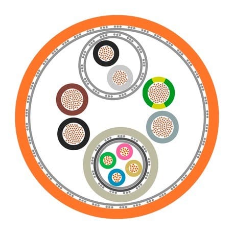
A one-cable solution replaces the separate power lead and feedback lead between drive and motor with a single jacketed assembly. The wiring cabinet benefits as much as the machine does: one connector pair instead of two to terminate, one clamp set instead of two to route, and a thinner bundle that lets a new installation be specified with a narrower drag chain. The engineering question inside a hybrid servo cable is how the cross-section is shared out between power, brake and feedback.
Key Specifications
| Product type | Hybrid power and feedback servo cable |
|---|---|
| Jacket material | PUR, orange |
| Conductor layout | Power cores plus brake pair plus signal cores, set per drive rating |
| Feedback protocols | Compatible with EnDat 3, HIPERFACE DSL, BiSS-C |
| Connector family | M23 / M40 hybrid circular or maker-specific shell |
| Temperature range | -40 to +80 degrees C moving – to be confirmed |
| Minimum bend radius | 7.5 x diameter – to be confirmed |
| Feedback screening | Screened pair with the screen carried to the connector shell |
How the cross-section is allocated
Public competitor data for this class quotes a structure of four 1.5 mm2 power cores together with two 1.5 mm2 brake cores and four signal cores. That is a real starting point and it is not a universal answer: conductor count and cross-section follow the drive rating and the feedback type, so the layout is set against your motor and drive nameplate before we quote.
| Function | What sets its size | What happens if it is under-sized |
|---|---|---|
| Motor power cores | Drive continuous and peak current, run length, duty cycle | Voltage drop at peak torque, drive trips on undervoltage |
| Brake pair | Brake coil current and the voltage the drive supplies | Brake releases late or holds weakly |
| Feedback pair or pairs | The protocol – clock and data need a screened pair | Following error, position drift, nuisance trips |
| Shield and fillers | Grouping needed to keep the bundle round under torsion | Cores migrate, the bundle flattens and the jacket wears |
Feedback inside a hybrid: the part people get wrong
Putting a digital feedback pair in the same sheath as the motor power conductors only works if the screening is right. The switching noise from the power cores is exactly what the feedback pair must not see.
| Protocol | What it needs in the hybrid | Note |
|---|---|---|
| EnDat 3 | One screened pair, screen continuous to the shell | Assignment follows the drive maker |
| HIPERFACE DSL | Screened pair, impedance controlled | Tolerant of longer runs within the same sheath |
| BiSS-C | Screened pair, point to point | Common on retrofit work |
| Sin/cos 1 Vpp | Two screened pairs, analog | Possible but the noisiest option in a hybrid – ask first |
Connector family
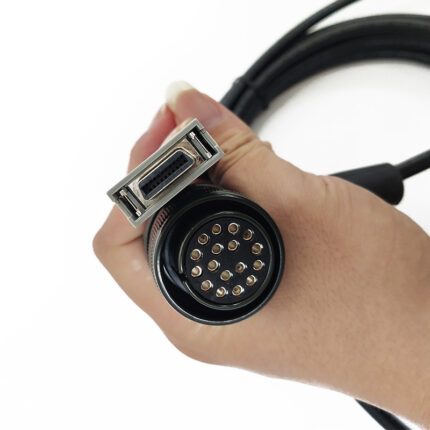
The hybrid shell is what makes a single-cable installation possible, and it is usually the constraint on the whole design. M23 and M40 hybrid circular shells cover most of the market and carry power, brake and signal contacts in one body. Where the drive maker uses a specific shell, we match it instead. Send the motor type and drive model and we match the connector family, whether that is a standard hybrid circular shell or a maker-specific one.
When one cable is the wrong answer
- Very high power axes – the power cross-section gets large enough that a separate power lead is easier to route and to terminate.
- Short runs with easy access – two cables cost less than one hybrid and are easier to replace individually.
- Axes with a separate brake supply – if the brake does not come from the drive, it may not belong in the sheath at all.
- Retrofits where only one of the two existing cables has failed – you lose the benefit if you are re-pulling a good cable anyway.
Mechanical figures still to be confirmed
PUR jacket in the orange machine-build color, chosen for oil and coolant exposure. Moving-installation temperature range quoted as -40 to +80 degrees C, and a minimum bend radius quoted as 7.5 times overall diameter in continuous chain duty. Cycle life and torsion figures have to be measured on the production build rather than taken from a brochure, so each is marked pending confirmation and flagged on the quote rather than printed as settled fact.
Typical applications for this hybrid servo cable
- New machine builds where the drag chain width is still open at design stage
- Retrofits that pull two worn cables and pull one back in, alongside our encoder feedback cable where the feedback run stays separate
- Machine tools, packaging lines and handling axes with long travel, using a M23 screw lock cable pattern at the drive end
- Axis wiring built up as a custom servo motor cable assembly where a hybrid is not the right answer
- Cells that also need a data path, paired with our Cat6a fiber hybrid cable back to the cabinet
How to specify
- Drive maker and model, so we match the shell and the pinout.
- Motor feedback type – the protocol, not just the connector.
- Run length, and whether the cable sits in a chain or is fixed.
- Brake arrangement – driven from the drive, or separately supplied.
- Environment – oil, coolant, temperature, and whether the run also twists.
Workmanship and testing
Workmanship follows IPC/WHMA-A-620 Class 3 and the line runs under ISO 9001. Conductors from 32 to 12 AWG are in range. Continuity and pinout are verified on 100% of units before packing; if you specify an ingress rating, seal checking on the batch can be quoted.
Custom builds and ordering
The prototype minimum is 5 pcs, out in 3 working days. Production starts at 500 pcs and ships 14 working days from approval. Tooling for a body we do not stock adds about 10 working days. Your part number, your label, your packaging – with material certificates and first-article reports on request.
Related assemblies
- Custom Servo Motor Cable Assembly
- Encoder Feedback Cable with PUR Jacket for Digital Servo Loops
- OEM Servo Encoder Cable Cross-Reference by Machine Family
- M23 Screw Lock Cable for Servo Motor Power and Encoder Feedback
- Cat6a Fiber Hybrid Cable for Machine to Cabinet Links
- Hybrid Robot Torsion Cable with CAT6 Data Pair
Most of these runs end on a machine tool axis or a packaging line; we build to the drive and motor nameplate, and the values your assembly is verified to are the ones on your order.
Frequently Asked Questions
Can I put the brake and the feedback in the same cable as the power?
Yes, that is the point of the build, provided the feedback pair is properly screened and the brake is driven from the drive. If the brake has a separate supply, it may not belong in the sheath.
What cross-section do I need?
Whatever your drive rating and run length require. We set the layout against the motor and drive nameplate rather than against a standard structure.
Is one hybrid always better than two cables?
No. On very high power axes, on short accessible runs, or where only one of two existing cables has failed, two separate leads are usually the better answer.
What is the minimum order?
Minimum for a prototype run is 5 pcs, out the door in 3 working days. Volume production starts at 500 pcs and ships 14 working days after you approve the sample.
| Product type | Hybrid power and feedback servo cable |
|---|---|
| Jacket material | PUR, orange |
| Conductor layout | Power cores plus brake pair plus signal cores, set per drive rating |
| Feedback protocols | Compatible with EnDat 3, HIPERFACE DSL, BiSS-C |
| Connector family | M23 / M40 hybrid circular or maker-specific shell |
| Temperature range | -40 to +80 degrees C moving – to be confirmed |
| Minimum bend radius | 7.5 x diameter – to be confirmed |
| Feedback screening | Screened pair with the screen carried to the connector shell |