

Choosing a connector locking mechanism looks like an ergonomic question and is really a physics question with a maintenance budget attached. Thread, bayonet and push-pull each hold the mated pair together by a different mechanism — threaded preload, ramp geometry, spring latches — and each fails differently under vibration, pull and repeated re-mating. “Which one is better?” is unanswerable until you know how often the line is disconnected, what pulls on the cable, and which vibration profile the installation must survive. This guide turns the three mechanisms into numbers: the retention equation a bayonet ramp actually obeys, the friction angle at which it self-locks, the cycle counts and test reports you should write into a specification, and the honest answer about what the standards do and do not say.
One honest note before the detail. HKWIRE is certified to ISO 9001, assemblies are built to IPC/WHMA-A-620 workmanship requirements, and material declarations are provided per project for RoHS and REACH. Where a comparison below is industry or vendor convention rather than a clause in a standard, the text says so — because a locking decision defended by folklore fails in exactly the way folklore cannot predict.
1. Three mechanisms, three physical ideas
A threaded connector generates axial preload: turning the coupling nut drags two ramped surfaces (the threads) against each other, and the elastic stretch of the nut and barrel becomes a clamping force that nothing short of torque can undo. A bayonet connector generates geometric capture: ramp tracks machined or molded into the shell let a spring-loaded follower ride in during insertion, then hold it captive at the end stop. A push-pull connector combines a spring-loaded sleeve with ramps of its own, so the same hand that inserts the connector also locks it, and pulling on the cable only tightens the capture.
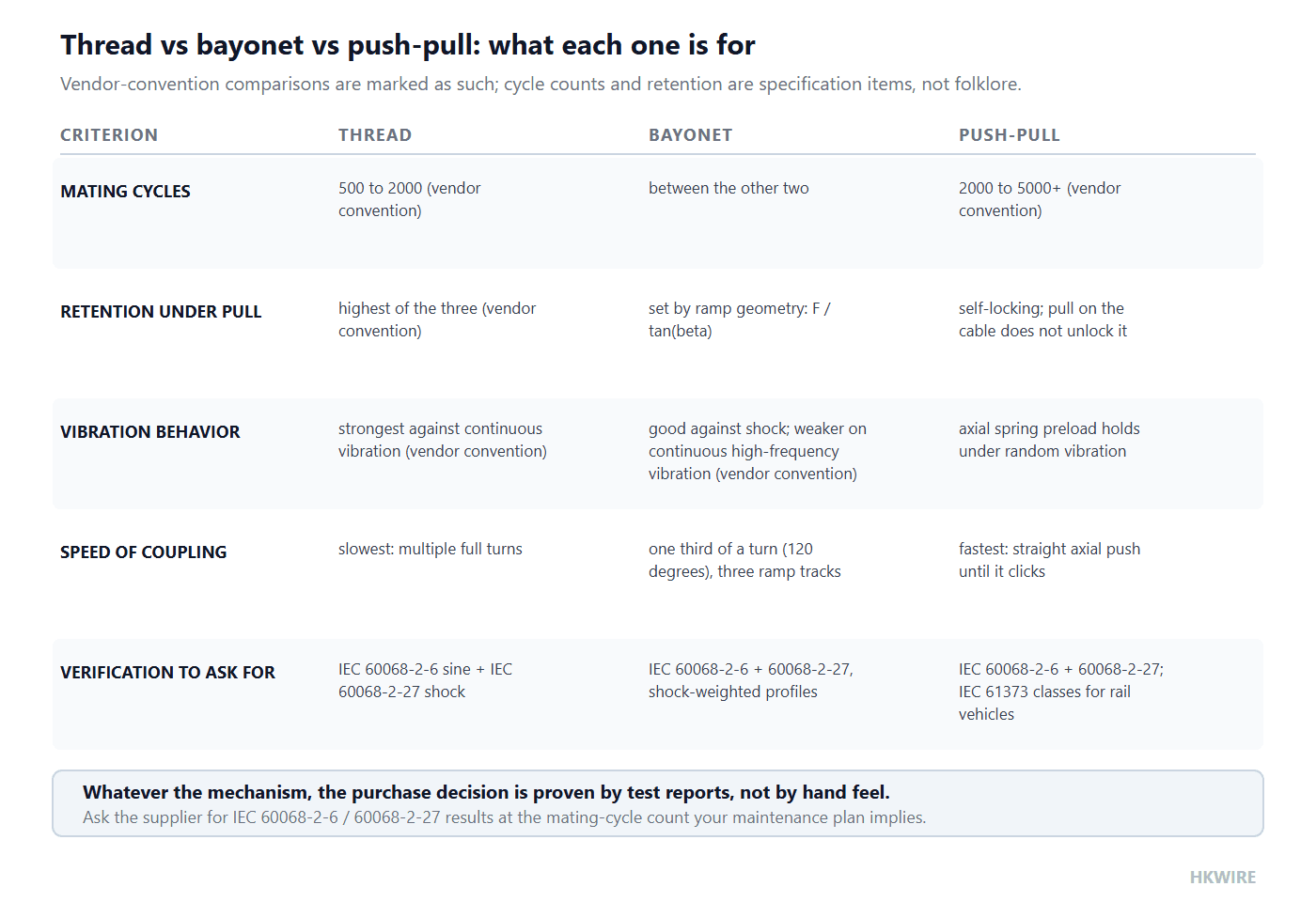
| Mechanism | How it holds | How it is released | Coupling speed | Mating cycles (vendor convention) |
|---|---|---|---|---|
| Thread | Threaded axial preload | Wrench or knurled nut, multiple turns | Slowest | 500–2000 |
| Bayonet | Ramp tracks + end stop | Short reverse rotation | One third of a turn (120°) | between the other two |
| Push-pull | Spring sleeve + ramps (self-locking) | Pull the release sleeve | Fastest: straight axial push | 2000–5000+ |
The cycle-count figures are vendor-convention ranges quoted across connector catalogs, not a clause in any standard; the ranking is the robust part, the endpoints are not.
Those three ideas produce three different failure modes under the same abuse. Preload relaxes (threads wear, plating creeps) and the connector rattles loose. A ramp can jump if shock drives the follower over the end stop. A spring sleeve can lose its preload. Which of these matters most is set by the application, which is why the sections that follow put numbers on each.
The vocabulary matters too, because vendors use “latch”, “ramp”, “sleeve” and “follower” loosely across families. A connector locking mechanism is therefore best specified by what it does — coupling action, retention figure with its test method, cycle rating, vibration evidence — rather than by what it is called. The sections below keep that discipline: every mechanism is reduced to the force balance that holds it, the test that proves it, and the maintenance plan that consumes it.
2. The retention equation behind a bayonet ramp
Strip a bayonet down to its skeleton and it is a wedge. A follower, pressed by a latch force, sits on a ramp of angle β; pulling the connector axially forces the ramp to climb over the follower. The geometry converts the latch’s normal force into an axial holding force with one line:
F_axial = F_latch / tan(β)
where F_latch is the normal force the spring or latch provides and β is the ramp angle measured from the connector’s axial direction. The smaller the ramp angle, the shallower the wedge and the larger the axial force it can resist — and, symmetrically, the harder the same ramp is to unlock, because unlocking means driving the follower back up the wedge. Read this way, a connector locking mechanism of the bayonet family is a wedge in disguise, and the catalog’s retention figure is the wedge’s rated output.
Worked example: the same latch at two ramp angles
| Step | Expression | Result |
|---|---|---|
| Axial hold at a 30° example ramp | 20 N / tan(30°) = 20 / 0.5774 | 34.6 N |
| Axial hold at a 15° example ramp | 20 N / tan(15°) = 20 / 0.2679 | 74.6 N |
| What doubling the hold costs | unlocking torque and insertion feel scale the same way | a stiffer, harder-to-mate connector |
The 20 N latch force and both ramp angles are worked-example assumptions chosen to show the sensitivity, not values from any standard; production ramp angles are vendor designs.
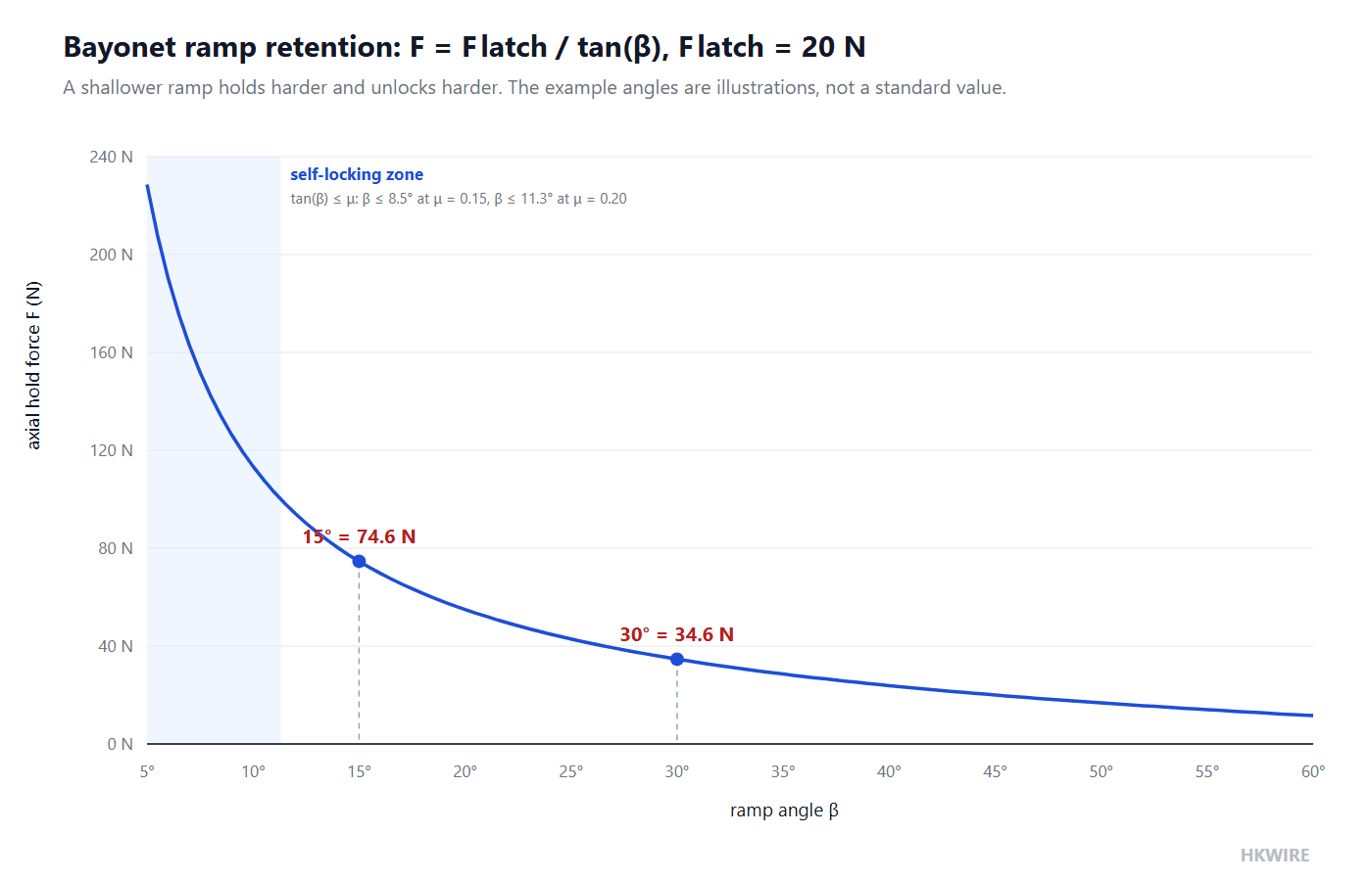
The curve’s shape is the design lesson. Halving the ramp angle more than doubles the holding force, which is why a small change in ramp geometry moves a connector family from “may work loose” to “requires a tool”. It also explains the coupling feel engineers learn to read: a connector that snaps together with authority is usually a steep, low-retention ramp, and one that needs a firm twist is buying its retention geometrically.
The latch force itself is not a free parameter. In most designs it comes from a spring the vendor sized to balance two requirements: firm enough that the follower stays engaged through handling, soft enough that a hand can mate the connector without a tool. That balancing act is why retention is a catalog figure rather than something a buyer can scale at will — doubling the retention of a connector locking mechanism means changing the spring, the ramp, or both, and the cycle rating changes with them. The equation above is the lever; the vendor’s test report is the limit.
A note on measuring the angle. Some vendors quote the ramp angle from the axial direction, others from the connector face, and the two conventions differ by ninety degrees. The equation in this guide assumes the angle is measured from the axial direction, which is the convention that makes small angles mean high retention. Before comparing two catalogs, check which convention each data sheet uses — a 15° ramp quoted from the face is a 75° ramp in this article’s terms, and comparing the two numbers directly would put the wrong connector on the drawing.
3. Self-locking is a friction angle, not a feeling
A bayonet that resists pull-off can still shake loose if vibration can walk the follower back down the ramp. The condition that prevents this is textbook mechanics, the same self-locking mathematics that governs power screws and inclined planes — see the friction treatment of power screws for the derivation in its conventional home:
tan(β) ≤ μ equivalently β ≤ arctan(μ), the friction angle
When the ramp angle sits at or below the friction angle, the axial load can never generate a force along the ramp large enough to overcome friction, and the mechanism cannot back-drive: the connector is self-locking.
Worked example: where the self-locking angle falls
| Step | Expression | Result |
|---|---|---|
| Self-locking angle at μ = 0.15 | arctan(0.15) | 8.5° |
| Self-locking angle at μ = 0.20 | arctan(0.20) | 11.3° |
| Reading | a ramp at or below the friction angle cannot back-drive | self-locking by geometry, not by preload |
The friction coefficients 0.15 and 0.20 are illustrative values for dry plastic-on-metal and metal-on-metal sliding surfaces respectively; the real coefficient of a plated, lubricated, worn surface belongs to the connector maker.
This is the conceptual split that general guides blur: a threaded connector stays mated because something was tightened (preload, which can relax), while a self-locking bayonet or push-pull stays mated because of the geometry (which cannot relax). They are two different insurance policies against the same vibration. Note also what the equation implies about lubrication and wear: anything that lowers μ — oil mist, plating that burnishes smooth — shrinks the friction angle and can move a marginal ramp out of self-lock. That is a maintenance question, and it is why cycle life and environment belong in the same paragraph as the geometry.
The same inequality explains a failure every engineer has seen: the coupling that unscrews itself. A thread is governed by identical mathematics — the screw is an inclined plane rolled into a cylinder — and a threaded coupling is self-locking only while the thread’s lead angle sits below its friction angle. That is why a dry, fine thread stays put while a lubricated, coarse one walks free under vibration, and it is why threaded couplings grow positive locks — spring washers, locking wires, locking rings — precisely in service environments expected to attack the friction that the mathematics relies on.
4. What the standards and catalogs actually say
The military circular-connector standard most often cited here is MIL-DTL-38999, and the claims that circulate about it deserve precision. What the series is known for, and what vendor documentation supports, is its Series I bayonet: three ramp tracks, locked by one third of a turn, 120°. What no public standard text supports is a specific ramp angle for those tracks — the oft-repeated figure circulates without a source, because the ramp geometry is the manufacturer’s design property.
Where retention does come with public numbers, it comes from a catalog tested to a named method. The LEMO B and S series publish exactly that: forces measured per the MIL-STD-1344A test method, across the size range, with a mechanical life of 5000 cycles.
| LEMO B/S size | Mating force Fv | Separation force Fd | Pull-off retention Fa | Mechanical life |
|---|---|---|---|---|
| 0B (smallest) | 10 N | from 7 N | 250 N | 5000 cycles |
| 5B (largest) | 48 N | up to 38 N | 800 N | 5000 cycles |
| Range across sizes | 10–48 N | 7–38 N | 250–800 N | 5000 cycles |
Pull-off retention, mating and separation forces from the LEMO B-series catalog, measured per MIL-STD-1344A; intermediate sizes fall between the endpoints shown, and the catalog is the authority. The LEMO B-series catalog and LEMO’s own locking-connector overview are public references.
Range endpoints deserve one caution. The 0B and 5B rows bracket the family, and intermediate sizes do not scale linearly between them; a real design takes its retention from the catalog’s per-size column, with the bracketing rows as a sanity check. The same discipline applies to the separation force: a connector locking mechanism specified on mating force alone can be difficult to disconnect in a crowded panel, which is why a serious catalog prints Fd beside Fv rather than letting the buyer guess.
The table rewards a second look at the ratio between columns. The pull-off retention is five to seventeen times the mating force, which is the signature of a push-pull self-locking mechanism: insertion needs to compress a spring, but extraction must defeat geometry. When a data sheet quotes retention without a method, or a mating force without a cycle count, the numbers cannot be compared to anything — insist on the test method name the way LEMO names MIL-STD-1344A.
5. Mating cycles are a maintenance budget
A locking mechanism is consumed by use, and the consumption rate is the least glamorous number in the selection. The convention across catalogs puts threaded mechanisms at roughly 500–2000 cycles and push-pull at 2000–5000 or more, with bayonet families typically between — treat all three as vendor conventions to be confirmed per part, and treat the ranking as the reliable content.
Worked example: converting a service plan into a cycle requirement
| Step | Expression | Result |
|---|---|---|
| Monthly calibration disconnects | 2 per month | 24 per year |
| Instrument service life | 10 years | 240 planned cycles |
| Engineering margin on cycles | × 5 | 1200 cycles required |
| Reading against the table above | 1200 vs the vendor-convention ranges | thread marginal, push-pull comfortable |
The 2 per month, 10 years and factor of 5 are this example’s assumptions; the comparison ranges are the vendor conventions from the first table.
The margin factor is doing real work in that calculation. A connector at 500 cycles of design life does not fail at 501; its retention degrades gradually as plating wears and latch springs take a set, which is precisely the degradation a vibration test at 0 cycles will never see. High-frequency maintenance — test points, calibration ports, medical and measurement equipment — is where the push-pull mechanism earns its cycle count and its one-handed speed at the same time.
The spectrum of real mating frequencies is also wider than most selections admit. A factory-floor sensor might be connected once and live there for a decade; a test-lab adapter might be mated fifty times a day. Between those poles sit devices mated per shift, per inspection or per reconfiguration, and the right connector locking mechanism is chosen at the pole the application actually occupies. The vendor-convention ranges in the first table are the ruler for that first cut; the part-specific rating is the final word.
6. Proving it survives: vibration and shock standards
Retention claims end at the shaker table door. The tests that separate a locking mechanism that survives from one that looks sturdy are the IEC 60068 series and, for rail vehicles, its demanding descendant:
| Standard | What it exercises | What it tells you about locking |
|---|---|---|
| IEC 60068-2-6 | Sinusoidal vibration sweep | Whether the mechanism walks loose or frets under continuous swept excitation |
| IEC 60068-2-27 | Mechanical shock | Whether a ramp can jump capture or a spring sleeve can bounce open under impulse |
| IEC 61373 | Rail-vehicle vibration and shock, in three classes: body, bogie, axle-mounted | Long-duration random profiles at severity levels a general test never approaches; the class must match the mounting location |
Method standards, not pass/fail thresholds: the acceptance profile and duration are agreed for the application, and the report must name the severity, axis and duration.
Two reading rules keep these tests honest. First, ask for the test report with severity, axis and duration, not for the phrase “tested to IEC 60068-2-6” — a sweep at mild severity proves very little about a locking mechanism. Second, match the class to the installation: IEC 61373 exists because a connector on a car body and one on an axle live utterly different vibrational lives, and specifying “61373” without naming body, bogie or axle class specifies nothing.
IEC 61373 is also instructive outside rail, because of its structure. It sorts the duty by where the component lives on the vehicle and writes a different profile for each location — the discipline any specification should imitate. The severity a connector locking mechanism must survive follows from its mounting environment, not from a generic “industrial” label: a marine panel, a machine-tool door and a traction axle are three different tests, and a single severity column cannot serve all of them.
7. Matching the connector locking mechanism to the application
The three mechanisms sort cleanly once the environment is stated, and most connector locking mechanism mistakes are environment mistakes: a mechanism praised in one application and condemned in the next is usually responding to a change in mating frequency, cable load or vibration profile rather than to a change in quality.
- Thread, where the connection is made once and disturbed rarely: panel-mounted power and signal entries, outdoor equipment, anywhere maximum preload and the strongest resistance to continuous vibration (vendor convention) outweigh coupling speed. A panel connector’s locking choice interacts with its mounting details — our guide to selecting a panel mount connector covers the flange, sealing and anti-rotation side of that decision.
- Bayonet, where speed and positive engagement matter: instruments and audio, chassis devices, connectors mated daily by hand. The 120° quarter-turn action is fast, can be made glove-friendly, and its retention is set by ramp geometry per the vendor’s design.
- Push-pull, where self-locking plus high cycles plus one-handed operation converge: medical devices, measurement and telecom hardware, anywhere the cable gets tugged. Because pulling the cable tightens rather than opens the lock, it is also the mechanism of choice where the connector is the cable’s anchor point — our M8 and M12 circular cable and screw-lock molded cable ranges give the common industrial connectors in both styles, and the same logic in miniature appears in the DIN 43650 valve connector guide, where a central screw takes the role of the thread.
One more coupling between sections: the mechanism locks the shells, but the termination anchors the cable. A push-pull connector whose crimp backs out transfers the retention problem one layer down, so the crimp pull-off requirements of IPC/WHMA-A-620 and the retention figures of the locking mechanism are two halves of one pull budget. The halves are proven differently — the crimp by pull-off tests on samples, the mechanism by the maker’s retention figure — but they fail together, which is the point.
One boundary also keeps this guide honest: keying and coding are not locking. A coded interface prevents wrong mating; it does not hold the mated pair together under vibration or pull. A connector locking mechanism and a keying scheme answer two different questions, and a connector chosen for its keying still needs its retention justified by the numbers in the sections above. When both matter — and in service tooling they usually do — specify them in separate sentences, with separate evidence.
8. Five things a general guide will not tell you
- The retention equation and its cost. F_axial = F_latch / tan(β) is why a 15° example ramp holds 74.6 N with the same 20 N latch that holds 34.6 N at 30° — and why the connector that holds hardest is also the one that is hardest to unlock. Retention and coupling effort are the same geometry read from two ends.
- Self-locking is tan(β) ≤ μ, a testable inequality. At μ = 0.15 the friction angle is 8.5°, at μ = 0.20 it is 11.3°. A ramp inside that zone cannot back-drive — a different guarantee from threaded preload, and one that can be lost by lubrication or wear that lowers μ.
- The ramp angle of a MIL-DTL-38999 bayonet is not public knowledge. Three ramps, one third of a turn — yes. “30 degrees” — no source. Any real ramp angle is the vendor’s design property; buy the measured retention, not the angle.
- Cycle counts are a maintenance calculation, not a catalog decoration. Two disconnects a month for ten years with a factor-of-five margin is 1200 cycles — a figure that quietly eliminates a threaded mechanism and hands the job to push-pull. Do the multiplication before reading the catalog, and remember the ranges are vendor convention.
- Vibration verification has named methods, and they are method standards. IEC 60068-2-6 (sine), 60068-2-27 (shock) and IEC 61373 (rail, by mounting class) tell you how a locking mechanism is exercised; the severity and pass criteria are yours to specify, and the report must name them.
How we help
Tell HKWIRE how often the connection is mated, what pulls on the cable and which environment it must survive, and we propose the connector locking mechanism, the connector family and the termination with the numbers named: retention with its test method, cycle ratings against your maintenance plan, and vibration evidence per IEC 60068-2-6, IEC 60068-2-27 or IEC 61373. Standard builds ship from our cable ranges; anything special goes through custom development.
Frequently asked questions
Is a bayonet connector less secure than a threaded one?
They secure differently. Threaded connectors hold by preload, which vendor convention rates strongest against continuous vibration, while a bayonet holds by ramp geometry and resists shock well. Vendor-convention rankings describe families, not parts: a well-designed push-pull can outperform a poorly designed thread. Security is not a mechanism verdict but a number — measured pull-off retention and vibration evidence for the specific part, compared against what your cable and environment impose.
What does “one third of a turn” mean on a bayonet connector?
Bayonet shells carry ramp tracks, and the MIL-DTL-38999 Series I convention is three ramps spaced 120 degrees apart, so locking the connector takes one third of a full rotation. Each of the three followers travels its own ramp, which is what keeps the mating force balanced and the engagement positive.
Why is there no published ramp angle for MIL-DTL-38999 bayonets?
Because the ramp profile is the connector maker’s design property, not a clause in the standard. The standard’s traceable content is the kinematics — three ramps, 120 degrees. A specific angle quoted in an article or forum post has no source; the defensible request is measured retention per the maker’s test method.
What friction coefficient should I assume when checking self-locking?
Treat 0.15 to 0.20 as the illustrative band for dry sliding surfaces used in this article’s example — 8.5 to 11.3 degrees of friction angle. The real value depends on materials, plating, lubrication and wear, which is exactly why a marginal self-lock design should be verified by test rather than by calculation alone.
How many mating cycles should I specify?
Work backward from your maintenance plan: disconnects per month times service life, times an engineering margin for retention degradation as plating and latch springs wear. The example in this guide — two per month, ten years, a factor of five — gives 1200 cycles. Compare that number against the vendor’s cycle rating for the specific part.
Which vibration standard applies to my connector?
IEC 60068-2-6 covers sinusoidal vibration and IEC 60068-2-27 covers shock for general equipment; IEC 61373 adds long-duration random profiles for rail vehicles in three mounting classes: body, bogie and axle-mounted. Name the class or severity, and require the report to show axis, duration and profile, not just the standard’s number.
Are push-pull connectors really self-locking?
Axially, yes by design: the same ramp geometry that captures the sleeve cannot be back-driven by a pull, which is why catalogs like the LEMO B series quote pull-off retention (250 N to 800 N across sizes) several times higher than the mating force. Self-lock against axial pull is not a guarantee against every load direction, so verify the release sleeve and side loads against the maker’s data.
Does the locking mechanism affect the cable termination?
It shares the same pull budget. The mechanism holds the shells together, while the crimp or solder holds the cable in the backshell, and the weaker of the two sets the assembly’s retention. Specify crimp pull-off per IPC/WHMA-A-620 section 19 minimums and the connector’s pull-off retention as one requirement, not two unrelated lines.







