M12 CAN Bus Cable, 5-Pin Shielded Pair for CANopen and DeviceNet
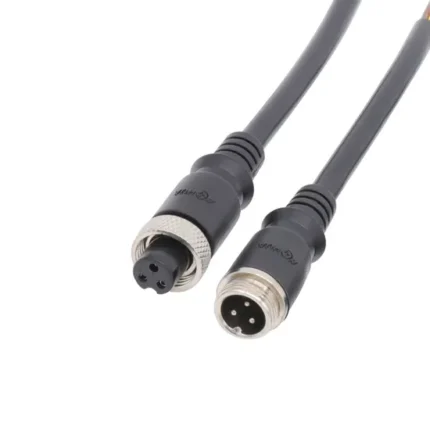
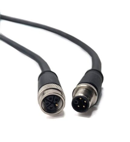
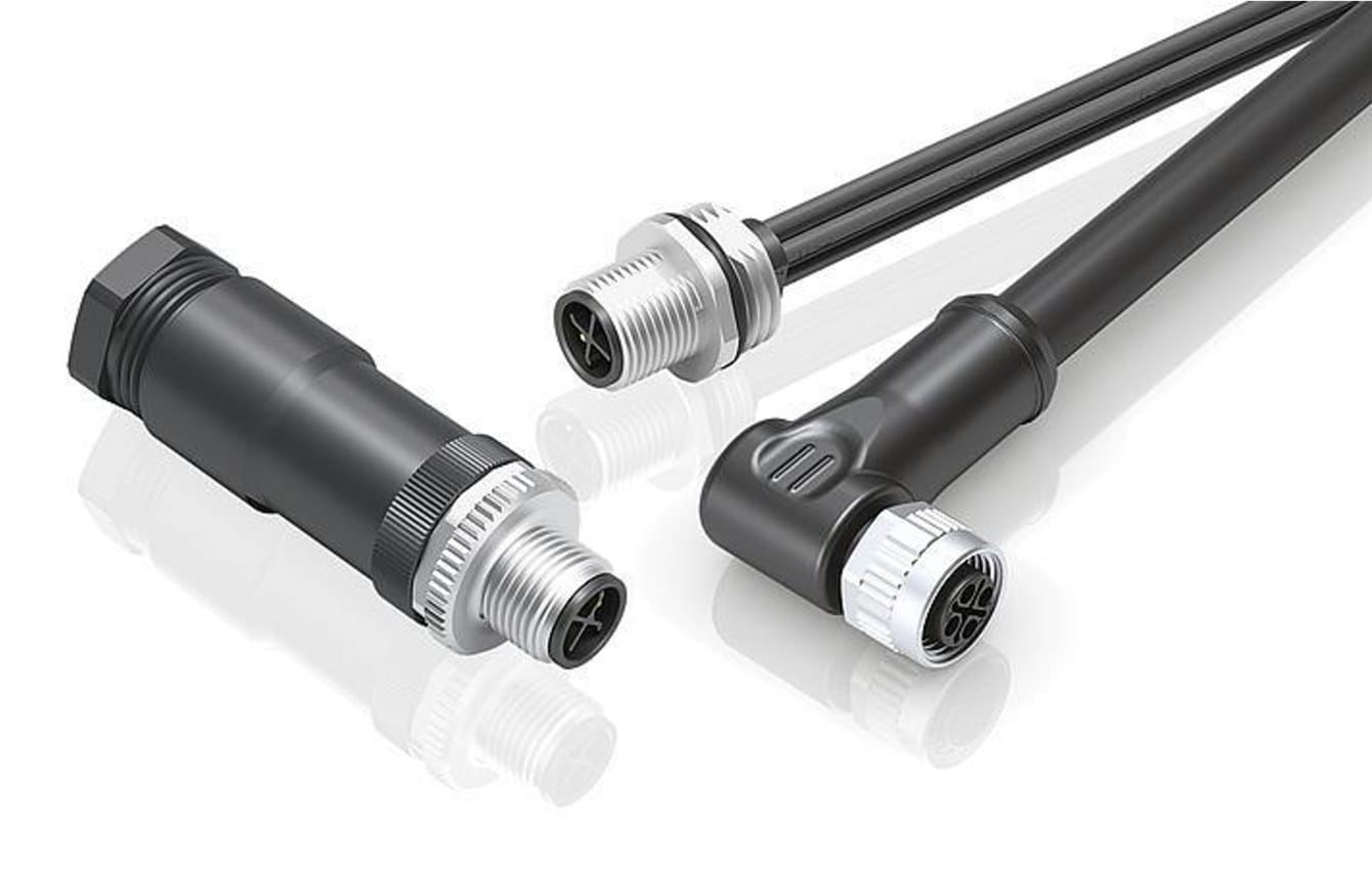
An M12 CAN bus cable built for stable CANopen and DeviceNet segments: one shielded twisted pair held at a controlled lay, the braid bonded to the coupling nut at both ends, and supply cores where the drop powers the node. Built to the pinout you send.
Last updated: 13 September 2026
Overview
An M12 CAN bus cable carries a single terminated differential pair, which is why it is far more sensitive to impedance and screen continuity than to conductor size. CAN is still the bus of choice wherever reliability matters more than bandwidth: mobile hydraulics, agricultural machinery, lifts, battery management systems and a very large installed fleet of motion controllers. We build the drop with the pair held at a controlled lay and the braid bonded to the coupling nut at both ends, to the pinout you send.
Key Specifications
| Coding | A-code, 5-pin, CAN fieldbus |
|---|---|
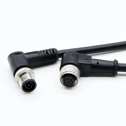
| Connector A | M12 A-coded 5-pin, straight or right-angle |
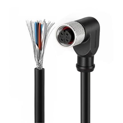
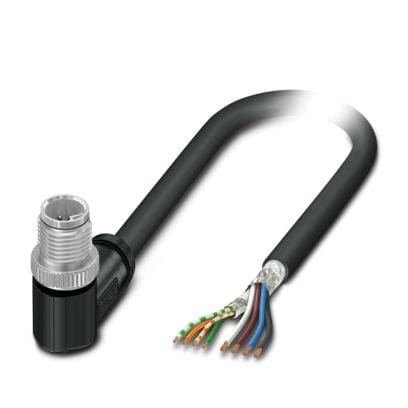
| Connector B | M12 A-coded 5-pin, or open leads for field termination |
| Signal conductors | One shielded twisted pair, controlled lay |
| Impedance | 120 ohm nominal – confirm per build |
| Supply cores | Node supply carried in the same cordset where specified |
| Jacket | PUR for oil and UV, PVC for indoor panels |
| Shielding | Braid bonded to the coupling nut at both ends |
| Ingress rating | IP67 when mated – confirm per build |
Why this coding exists: keeping fieldbus out of sensor ports
CAN on M12 uses the ordinary A-coded 5-pin shell, which is convenient and slightly dangerous. It is the same shell as a five-core sensor cordset, so nothing mechanical stops an installer plugging a CAN drop into a sensor port or the other way round. On a machine where both exist, the practical defenses are physical: key the ports differently at the panel, hold different jacket colors, and print the function on the overmold. We can do all three.
Two numbers decide whether a segment is stable
The CAN physical layer is a single terminated differential pair, which is why two numbers decide whether a segment is stable. The first is characteristic impedance – the pair needs to sit in the 120 ohm nominal band so reflections do not corrupt the edges. The second is the screen. On mobile machinery the bus runs past alternators, hydraulic pumps and inverter drives, and an unscreened pair accumulates errors that present like software bugs: intermittent and load-dependent. We control the pair lay during stranding and land the braid on the coupling nut at both ends so the screen path is continuous through the connector.
A-code 5-pin CAN pinout reference
The assignment below follows the convention published for CANopen and DeviceNet drops. Wire colors are the part that varies most between makers, so treat the pin functions as the contract and the colors as a proposal.
| Pin | CANopen (CiA convention) | DeviceNet | Typical color | Note |
|---|---|---|---|---|
| 1 | CAN_SHLD – screen | Drain | Bare / shield | Landed on the coupling nut, not floated |
| 2 | CAN_V+ – bus supply | V+ (24 V) | Red | Only present where the drop powers the node |
| 3 | CAN_GND – supply return | V- | Black | Return for pin 2 |
| 4 | CAN_H | CAN_H | White | Dominant-high side of the differential pair |
| 5 | CAN_L | CAN_L | Blue | Dominant-low side of the differential pair |
Where your device does not follow this assignment, send the pinout. We terminate to your drawing, not to a color chart, and keep the pair twisted right up to the contact.
How CAN sits in the M12 coding family
CAN uses the general-purpose A-code, the same shell as ordinary sensor wiring. The table below is the whole map: what each code carries, how many positions it uses, and where it turns up.
| Code | Positions | Carries | Typical use |
|---|---|---|---|
| A | 3 / 4 / 5 / 8 / 12 | DC sensor supply and signals, IO-Link | Proximity switches, photoelectric sensors, valve plugs |
| B | 5 | PROFIBUS-DP fieldbus | Legacy drives, remote I/O racks, weigh scales |
| C | 3 to 6 | AC power, dual keyway, extended earth | AC sensors, solenoid coils, legacy actuator blocks |
| D | 4 | 100 Mbit/s Ethernet over two pairs | PROFINET, EtherNet/IP, EtherCAT device drops |
| K | 4 + PE | Three-phase AC power | Motor feeds, power distribution blocks |
| L | 4 + PE | DC power | IO-Link power, AGV and drive supplies |
| M | 5 + PE | Three-phase motor plus brake pair | Servo and geared motors with holding brake |
| P | 4 + PE | Data pairs plus 24 V DC supply | Single-cable EtherCAT and remote I/O blocks |
| S | 3 + PE | Single-phase AC power | Field I/O blocks, cabinet heaters, pumps, fans |
| T | 4 | DC power, two circuits | Low-voltage DC distribution |
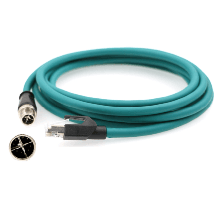
| X | 8 | Up to 10 Gbit/s Ethernet over four pairs | Machine vision, M12 to RJ45 10G links |
| Y | 6 + PE / 8 | Hybrid power plus Fast Ethernet | Valve islands, hybrid power and data drops |
A, B, C and D are defined in IEC 61076-2-101, X in IEC 61076-2-109 and the power codings in IEC 61076-2-111. These are the industry-standard descriptions of what each coding is used for; the impedance, current and voltage figures your assembly is built and verified to are the ones stated on your drawing.
What happens when the drop is wrong
- Screen floated at one end – the bus works on the bench and errors under load. The most common cause of a “software problem” that is actually a cable.
- Pair untwisted at the connector – impedance rises locally and the edge degrades; the segment fails at the far end first, which points the finger at the wrong node.
- Termination missing or doubled – reflections on a long segment, usually blamed on the cable.
- Undersized supply cores – the node browns out at the end of a long drop and re-enumerates.
Segment topology matters more than cable length
If the segment is long or the node count is high, send us the topology. A sketch with node spacing is enough for us to advise on conductor size, on whether you need a terminating resistor at the far end, and on whether the drop lengths are short enough for the bit rate you intend to run. Every drop is checked for continuity and for shorts between the pair and the screen before it ships.
Typical applications for this M12 CAN bus cable
- Mobile hydraulic machinery and construction equipment
- Agricultural implements and tractor-to-implement links, alongside our M12 ISOBUS Lite cable
- Battery management and charging systems
- Lift and escalator control, medical carts, AGV fleets
- Marine networks using NMEA 2000 drop cable in the same 5-pin shell
- Rolling stock control networks – see our M12 rail signal cable
What we need from you
- Pinout, or the device part number
- Whether the drop carries node supply
- Length, and the segment topology if the run is long
- Shielded or unshielded, and where the screen lands
- Jacket exposure – oil, UV, coolant, washdown
- Quantity, and whether this is a prototype or a production order
Workmanship and testing
Each assembly is built and inspected to IPC/WHMA-A-620 Class 3 criteria within an ISO 9001 quality system, covering 32 to 12 AWG. Continuity and pinout are tested on every unit before packing. Where the specification calls for an ingress rating, seal checking on the batch can be quoted.
Custom builds and ordering
Five pieces is where a prototype starts and it ships in 3 working days. Production requires 500 pcs minimum and takes 14 working days after approval. Non-stock tooling adds around 10 working days. Private-label builds ship under your part number and labeling; material certificates and first-article reports are available on request.
Related CAN and M12 assemblies
- M12 4-pin A-coded right-angle shielded sensor cable
- M12 A-code Y-splitter sensor cable
- M12 rail Ethernet cable for rolling stock
- M12 IP68 / IP69K food-grade stainless steel washdown cable
- M12 drag chain cable for continuous flexing
- M12 IO-Link cable for master to device drops
Full range: Circular M8 and M12 cable assemblies.
Frequently Asked Questions
Is 120 ohm the impedance of the cable or of the bus?
Of the bus. The pair in the cable is built to sit in the 120 ohm nominal band; the figure for your build is confirmed per order.
Can you terminate only one end and leave flying leads?
Yes. M12 to open leads is a standard option, and we can supply the matching connector separately.
Why does my segment fail only when the hydraulics run?
Usually screen continuity or pair geometry rather than a protocol issue. Check that the braid is bonded at both ends and that the pair is twisted up to the contact.
Do you supply terminating resistors?
We can build the termination into the last drop when you tell us the segment layout, which is more reliable than one added on site.
| Connector A | M12 A-coded 5-pin, straight or right-angle |
|---|---|
| Connector B | M12 A-coded 5-pin, or open leads for field termination |
| Coding | A-code, 5-pin, CAN fieldbus |
| Impedance | 120 ohm nominal – confirm per build |
| Jacket | PUR for oil and UV, PVC for indoor panels |
| Shielding | Braid bonded to the coupling nut at both ends |
| Ingress rating | IP67 when mated – confirm per build |
| Signal conductors | One shielded twisted pair, controlled lay |
| Supply cores | Node supply carried in the same cordset where specified |