

An M12 distribution box is normally bought as an accessory: priced by the port count, checked against the sensor current, and pushed into the bill of materials without a second look. On a 24 V machine that is where selection quietly goes wrong. Every ampere a sensor draws travels out along the trunk and back along the return, so the copper in that trunk sits in series with your entire I/O field. This article covers what a passive box is actually rated for, why that rating moves, and how to size the trunk conductor from a voltage budget you set rather than one you inherit.
1. What an M12 Distribution Box Actually Contains
A passive distribution box is a wiring convenience, not an electronic device. One trunk enters through a gland or molded transition, the supply pair and the return fan out to every port, and the only active part is a status LED per channel. There is no fuse, no current limiting, no short-circuit protection.
Port counts of 4, 6 and 8 are the standard offering. What matters more than the count is how many signal paths each port carries:
- 4-pole port — one signal path (pin 4), single-occupied.
- 5-pole port — two signal paths (pin 2 and pin 4), which manufacturers call double-occupied. An 8-port box with 5-pole ports exposes 16 channels, not 8.
That is why the current vocabulary needs two separate words. Manufacturers rate 2 A per path and 4 A per slot. A Pepperl+Fuchs SACB-4/4-L is documented as ≤2 A per channel and ≤4 A per slot. Collapsing both numbers into one figure is the first thing that goes wrong in a datasheet comparison, because a double-occupied 5-pole port must be counted as two 2 A paths.
Standard trunk builds are consistent across vendors: 8 × 0.34 + 3 × 0.75 in PUR or PVC, and 8 × 0.5 + 3 × 1.0 in PUR. Stock lengths are 3, 5, 10 and 15 m, and every catalog adds “further cable lengths on request” — so the length limit is a calculation, not a catalog figure.
Housing and protection: IP65/IP67 is the baseline, with IP68 on metal versions, IP69 on the Lapp range and IP69K on Turck stainless-steel types. The K in IP69K comes from ISO 20653, which superseded DIN 40050-9, and is not an IEC 60529 designation. Housings are PBT, PA, PUR-potted or die-cast zinc, and operating temperature is quoted from −25 to +80 °C by Phoenix Contact and −40 to +80 °C by Turck — it follows the cable and the seal, not the box.
Finally, keep the connector rating separate from the box rating. Under IEC 61076-2-101:2024, an A-coded M12 contact is rated 4 A for 2–5 poles, 2 A for 6–8 poles and 1.5 A for 9–12 poles. Those are contact ratings, and they say nothing about what a finished M12 distribution box can distribute.
2. The Total Rating Is a Range, Not a Constant
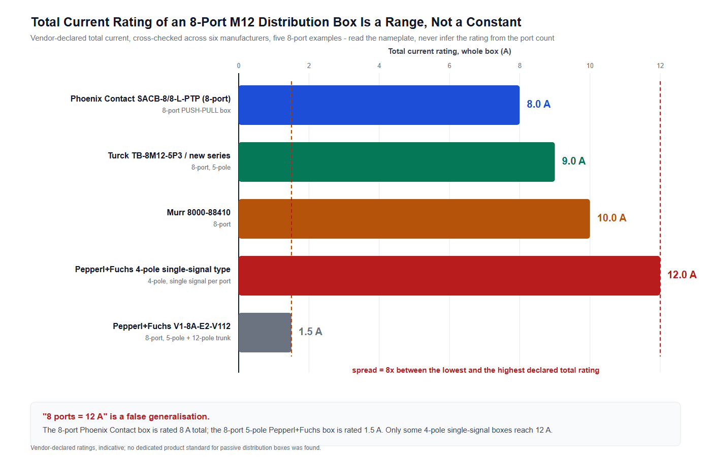
Ask six manufacturers for the total current rating of an 8-port box and you get six different answers, all of them declared rather than derived.
Table 1. Declared total current rating of 8-port passive M12 distribution boxes. Ratings are vendor-declared and indicative; verify against the current data sheet.
| Vendor and part | Ports / poles | Declared total | Note |
|---|---|---|---|
| Phoenix Contact SACB-8/8-L-PTP | 8 / 5-pole, PUSH-PULL | 8 A | 8 A across 8 slots is 1 A per slot. |
| Turck TB-8M12-5P3 | 8 / 5-pole | 9 A | |
| Murr 8000-88410 | 8 / 5-pole | 10 A | Per-contact current specified at 40 °C. |
| Pepperl+Fuchs 4-pole single-signal | 8 / 4-pole | 12 A | Reached because each slot carries one path. |
| Pepperl+Fuchs V1-8A-E2-V112 | 8 / 5-pole, 12-pole trunk | 1.5 A | Same port count, one eighth of the current. |
The spread is a factor of eight, and it is not noise. Three variables move the number:
- Pole count and occupancy. A double-occupied 5-pole box has twice as many conducting paths in the same housing, so the internal bus and the LED board both see the sum.
- Trunk cross-section. A 3 × 0.75 power group and a 3 × 1.0 group do not terminate in the same internal hardware, and the smaller group limits the total.
- Temperature basis. Where vendors state one at all, it is 40 °C: Lumberg writes “4 A per outlet / 12 A max. total; at 40 °C”, and Murr writes “operating current per contact (40 °C) max. 4 A”.
Why you cannot look the answer up. A passive distribution box has no dedicated product standard. The IEC 61076-2 series consists of connector detail specifications — part 101 for M12, part 104 for M8, part 109, part 111 for power, part 113 for hybrid — and none covers a passive splitter as a product. IEC 61984 applies only above 50 V or where a detail specification references it, which 24 V DC does not. UL 2238 addresses splitters’ construction rather than stating a current figure. So every rating you read is a manufacturer’s own declaration. Ask for the derating data behind it; most vendors publish no derating curve, and a supplier who cannot produce one has not measured it.
This is also why the widely repeated assumption that eight ports carry twelve amperes is a false generalisation. It fits some four-pole single-signal boxes, and it fails on the Phoenix Contact unit declared at 8 A and badly fails on the Pepperl+Fuchs unit declared at 1.5 A. Read the nameplate on the M12 distribution box in front of you, then treat that number as the ceiling for the whole trunk.
3. Trunk Voltage Drop: One Expression to Rule the Sizing
Once the total current is known, the trunk becomes a series resistance problem. If you size power cables by ampacity, this is the second half of the same exercise — ampacity sets the thermal limit, voltage drop sets the functional limit — and on a 24 V sensor trunk the voltage limit binds first:
I = total trunk current in amperes
R′ = conductor resistance per meter in Ω/m at the working temperature
Temperature is not a second formula; it is a coefficient on R′. R′ at temperature t is R′ at 20 °C multiplied by kT = 1 + 0.00393 (t − 20), using the copper coefficient 0.00393 per °C with a 234.5 K constant, valid from −20 to +100 °C. Fold that factor into R′ and the expression above never changes.
The values below come from the IEC 60228 Class 5 table for plain copper at 20 °C. Class 5 begins at 0.5 mm², so 0.34 mm² does not appear; that value is a vendor measurement.
Table 2. Conductor resistance per meter, converted from IEC 60228 Class 5 maximum DC resistance at 20 °C for plain copper.
| Cross-section | Ω/km at 20 °C | Ω/m at 20 °C | AWG approx. |
|---|---|---|---|
| 0.34 mm² | not in Class 5; measured ≈60 | 0.0600 | ≈22 |
| 0.50 mm² | 39.0 | 0.0390 | ≈20 |
| 0.75 mm² | 26.0 | 0.0260 | ≈18 |
| 1.00 mm² | 19.5 | 0.0195 | ≈17/18 |
| 1.50 mm² | 13.3 | 0.0133 | ≈16 |
| 2.50 mm² | 7.98 | 0.00798 | ≈14 |
Worked example: 8 ports, 8 A, 10 m trunk, 0.75 mm²
Take the most common field case: an 8-port box fully loaded at 0.5 A per path over 16 paths, a 10 m trunk to the cabinet, and 0.75 mm² supply and return cores — the standard power group in an 8 × 0.34 + 3 × 0.75 build.
- R′(0.75) = 0.0260 Ω/m. The loop is 2 × 10 m = 20 m, so R = 0.520 Ω.
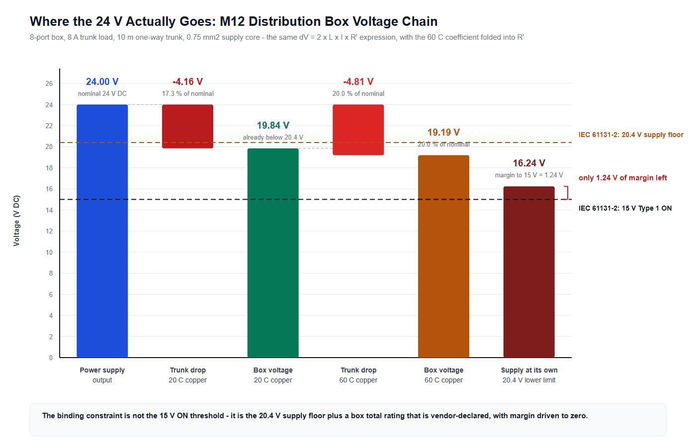
- ΔV = 8 A × 0.520 Ω = 4.16 V = 17.3 % of 24 V, leaving 19.84 V at the box.
- At 60 °C, kT = 1.157, so ΔV = 4.81 V = 20.0 %, leaving 19.19 V.
Four conclusions follow, and only one is the one people expect:
- 17.3 % is far beyond the 5 % voltage-drop convention, which is house practice rather than an IEC limit.
- 19.84 V is already below 20.4 V, the lower limit of the 24 V DC supply range defined by IEC 61131-2 (−15 % / +20 %, i.e. 20.4 to 28.8 V). A device powered to that standard is out of its supply window.
- But 19.84 V is still above the 15 V ON threshold of a Type 1 digital input, so nothing fails to switch. Type 1 has a 5–15 V transition band and a 15–30 V ON band; Type 2 and Type 3 need only 11 V.
- If the supply sits at its own lower limit of 20.4 V, the box sees 20.4 − 4.16 = 16.24 V — only 1.24 V above the ON threshold, before contact resistance or branch drop.
The binding constraint is therefore not the input threshold. It is the box total rating, the 20.4 V floor, and margin driven to zero.
Sensitivity: cross-section against length
Table 3 runs the same expression across the field range of 3 to 15 m at the same 8 A and 24 V.
Table 3. Trunk voltage drop at 8 A, in volts with the percentage of 24 V in brackets. Same expression, same constants.
| Supply core | 3 m | 5 m | 10 m | 12 m | 15 m |
|---|---|---|---|---|---|
| 0.34 mm² | 2.88 V (12.0%) | 4.80 V (20.0%) | 9.60 V (40.0%) | 11.52 V (48.0%) | 14.40 V (60.0%) |
| 0.50 mm² | 1.87 V (7.8%) | 3.12 V (13.0%) | 6.24 V (26.0%) | 7.49 V (31.2%) | 9.36 V (39.0%) |
| 0.75 mm² | 1.25 V (5.2%) | 2.08 V (8.7%) | 4.16 V (17.3%) | 4.99 V (20.8%) | 6.24 V (26.0%) |
| 1.00 mm² | 0.94 V (3.9%) | 1.56 V (6.5%) | 3.12 V (13.0%) | 3.74 V (15.6%) | 4.68 V (19.5%) |
| 1.50 mm² | 0.64 V (2.7%) | 1.06 V (4.4%) | 2.13 V (8.9%) | 2.55 V (10.6%) | 3.19 V (13.3%) |
| 2.50 mm² | 0.38 V (1.6%) | 0.64 V (2.7%) | 1.28 V (5.3%) | 1.53 V (6.4%) | 1.92 V (8.0%) |
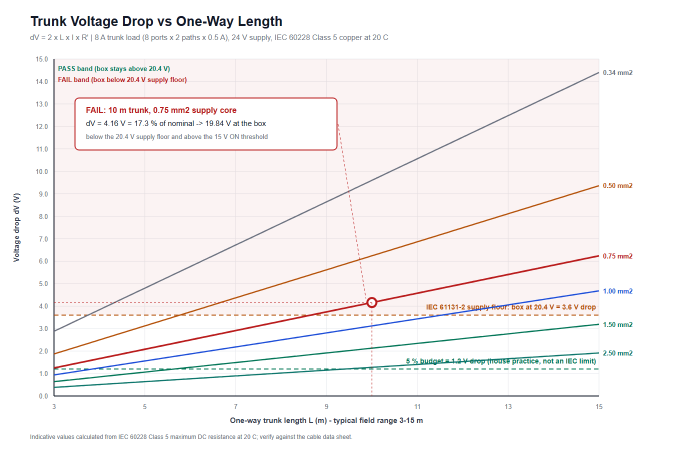
The conclusion sits where most people do not look: a common 10 m trunk on 0.75 mm² does not pass. Neither does 0.75 mm² at 12 m or 15 m, and 0.50 mm² fails from 5 m onward. Only 1.0 mm² and above keep the box inside the 20.4 V window across the whole 3–15 m range, and 1.5 mm² is where margin becomes comfortable.
For reference, the 1.0 mm² trunk Murr ships as an 8 × 0.5 + 3 × 1.0 assembly gives 3.12 V and 13.0 %, landing the box at 20.88 V — just clear of the floor at 10 m.
4. Sizing an M12 Distribution Box Trunk by Reverse Budget
Most articles list specifications. Very few let you start from the two numbers you actually have and work backwards: the total rating on the nameplate, and the drop you are willing to accept. Take the same expression and solve it for R′ instead of for ΔV — one rearrangement, not a second formula:
Run it at 8 A for three trunk lengths against two budgets: an aggressive 5 % (1.2 V), and the 20.4 V supply floor, which allows 24 − 20.4 = 3.6 V.
Table 4. Reverse budget at 8 A. Minimum cross-section is the smallest entry in the standard ladder (0.34, 0.5, 0.75, 1.0, 1.5, 2.5 mm²) whose R′ stays under R′max.
| Trunk length | Budget | ΔVallow | R′max | Minimum supply core | Result |
|---|---|---|---|---|---|
| 5 m | 5 % convention | 1.20 V | 0.0150 Ω/m | 1.50 mm² | 1.06 V, 4.4 % — passes |
| 10 m | 5 % convention | 1.20 V | 0.0075 Ω/m | none in the ladder | 2.50 mm² still gives 1.28 V, 5.3 % |
| 15 m | 5 % convention | 1.20 V | 0.0050 Ω/m | none in the ladder | 2.50 mm² gives 1.92 V, 8.0 % |
| 5 m | 20.4 V supply floor | 3.60 V | 0.0450 Ω/m | 0.50 mm² | 3.12 V, 13.0 % — passes |
| 10 m | 20.4 V supply floor | 3.60 V | 0.0225 Ω/m | 1.00 mm² | 3.12 V, 13.0 % — passes |
| 15 m | 20.4 V supply floor | 3.60 V | 0.0150 Ω/m | 1.50 mm² | 3.19 V, 13.3 % — passes |
Two things follow.
First, the 5 % convention, taken literally, is unreachable at 10 m and beyond. Meeting 1.20 V at 8 A over 10 m needs R′ below 0.0075 Ω/m, finer than the 2.5 mm² rung at 0.00798 Ω/m, and no vendor supplies an 8-port box with a standard trunk that heavy. So the 5 % figure is not a target you reach by picking a bigger core; it is a signal that 8 A over 10 m of sensor trunk is itself an architectural choice worth revisiting.
Second, the supply floor is the budget that actually binds, and it is a number you can defend: 3.6 V buys 1.0 mm² at 10 m and 1.5 mm² at 15 m. That is a specification you can put on a purchase order.
5. Three Loads That Never Make It Into the Budget
The LED standing current is not zero
Pepperl+Fuchs documents “operating current IB ≤ 5 mA per channel indication element”. On an 8-port box with double-occupied ports that is 16 channels, so up to 80 mA of standing current before a single sensor is energised. In a battery- or UPS-fed installation that is not zero: 80 mA continuously is 1.92 Ah per day, and it moves the 0.75 mm² 10 m case from 4.16 V to 4.20 V.
Conductor resistance at 60 °C is not the catalog figure
Table 2 is a 20 °C table. A trunk routed through a machine frame or bundled with power cables runs far hotter than the ambient the panel designer assumed. The kT coefficient is 1.079 at 40 °C, 1.157 at 60 °C and 1.197 at 70 °C, so that gap is the difference between 17.3 % and 20.0 % of nominal in the worked example.
Contact resistance and branch drops sit on top
The trunk loop is only part of the path. Each M12 mating pair, the crimp terminations inside the box and the field cable to the sensor all add resistance in series, and the branch cable repeats the same calculation at a shorter length. None of that is in the 4.16 V figure, which is why an M12 distribution box calculated at 19.84 V on the bench can read lower in the field.
6. Inspection Points, Failure Modes and a Selection Checklist
Because the box has no electronics, the failure modes are few and predictable, and the ones that show up in the field are almost always consequences of the voltage budget:
- Sensor resets and spurious low readings on the ports furthest from the cabinet, appearing only when all ports are loaded. Measure at the box, not at the supply.
- Brownout on actuator inrush. A valve or small drive drawing a spike through the same trunk sees the full loop resistance, so the drop scales with the peak rather than the average.
- Corrosion at the port. An IP69K housing on a washdown line mated to an IP67 cable means the assembly rating is the lower of the two.
- Duplicate-port confusion. A 5-pole double-occupied box counts 16 channels, so an engineer who assumed 8 will mis-map two sensors to one path.
The selection checklist that follows:
- Read the total current rating off the nameplate. Do not infer it from the port count, and do not carry a number over from another vendor.
- Confirm paths versus slots: 2 A per path, 4 A per slot. Count a double-occupied 5-pole box as 16 paths.
- Ask the supplier for derating data above the stated 40 °C basis. If none exists, treat the rating as unqualified above 40 °C.
- Set a trunk voltage budget explicitly — the 20.4 V floor or a percentage you can defend — then size the supply core by the reverse budget.
- Re-check the budget at the box’s maximum operating temperature, not at 20 °C.
- Record the expected voltage at the box on the drawing, so a commissioning reading is judged against a number rather than a feeling.
7. M12 Distribution Box Trunk Assemblies from HKWIRE
At HKWIRE we build the trunk side of this problem: molded and overmolded M12 and M8 cable assemblies, distribution-box trunk cables in 8 × 0.34 + 3 × 0.75, 8 × 0.5 + 3 × 1.0 and custom constructions, in PUR and PVC, across the 3–15 m range industrial field wiring actually uses. Each is produced to drawing with the cross-section, the loop resistance and the calculated voltage at the box documented, so the number you sized for is the number you receive.
We are an ISO 9001 certified manufacturer. We do not hold IATF 16949 or ISO 13485, and we do not present them. Assemblies are built to the applicable standard rather than under a certification mark, and material declarations for RoHS and REACH are provided per project. Ratings that depend on your installation conditions are quoted per drawing.
Start from the two numbers you already have — the nameplate current and the acceptable drop — and we will return a cross-section, a length limit and the resulting voltage at the box. See the M8 and M12 circular cable range for standard trunks, or the M12 drag-chain cable where the trunk is continuously flexing. Typical pairings we ship against a passive box include the M12 L-code 16 A power cable where a slot carries more than 2 A, the M12 IO-Link cable for single-point sensor drops, and the M12 bulkhead panel connector where the trunk passes through a cabinet wall.
8. FAQ
Is there a standard total current rating for an M12 distribution box?
No. Cross-checking six vendors returns 8 A, 9 A, 10 A, 12 A and even 1.5 A for the same nominal 8-port format. There is no dedicated product standard for a passive box: the IEC 61076-2 series specifies connectors, not splitters, and IEC 61984 does not apply at 24 V DC. Every rating is a manufacturer’s declaration, so read it from the nameplate and ask for the temperature-rise data behind it.
Does a higher port count mean a higher current rating?
No. The twelve-ampere figure often attached to an eight-port box is a false generalisation. It fits some four-pole single-signal boxes, but the 8-port Phoenix Contact SACB-8/8-L-PTP is declared at 8 A total, and the 8-port 5-pole Pepperl+Fuchs V1-8A-E2-V112 is declared at 1.5 A.
Why do ratings say 2 A per path and 4 A per slot?
A 5-pole port carries two signal paths, on pin 2 and pin 4. Each path is rated 2 A and the slot as a whole is rated 4 A. A double-occupied 8-port box therefore exposes 16 paths, and the trunk current is the sum of the path currents, not the sum of the slot ratings.
Is a 5 % voltage drop a standard requirement for a 24 V sensor supply?
No. The hard numbers are the IEC 61131-2 supply range of 20.4 to 28.8 V and the digital-input thresholds: Type 1 switches ON between 15 V and 30 V, Type 2 and Type 3 between 11 V and 30 V. The 5 % figure is a house convention, not a standard.
How far can an M12 distribution box trunk run at 8 A?
Against the 20.4 V supply floor, which allows 3.6 V of drop: about 10 m on 1.0 mm², 15 m on 1.5 mm² and 22 m on 2.5 mm². Against a 5 % budget the limits collapse to roughly 3.9 m on 1.0 mm² and 2.9 m on 0.75 mm². Vendors publish no maximum length, so the limit is a voltage calculation.
Send the nameplate current, the trunk length and the drop you can accept. We will return a cross-section, a length limit and the calculated voltage at the box, with the loop resistance documented on the drawing.







