

Every argument about cca vs copper cable ends the same way: one side quotes a price per kilogram, the other a conductivity percentage, and nobody states the deciding constraint. Copper-clad aluminum is not cheap copper. It is a different conductor, with a different resistivity, density, expansion rate and termination chemistry. Engineering judgment comes down to four questions: how much cross-section you must add to reach the same resistance, what that does to weight, whether the terminal still works after five years, and whether the standards recognize the material. This article works all four.
CCA vs Copper Cable: Start With the Resistance Table, Not the Price Tag
Cca vs copper cable debates go in circles because the two sides answer different questions. A buyer asks what the conductor costs; a designer asks what it does. They only meet at one number: resistance per unit length. Voltage drop, heating, ampacity in a bundle, crimp barrel size and PoE survival are all downstream of it. Conductivity percentages, AWG numbers and prices per meter are not comparable until converted into it.
So the method here is narrow. Take the resistance the design allows. Work out what cross-section copper-clad aluminum needs to hit it. Then check whether that fatter conductor still fits the terminal, the clamp, the bend radius and the standard you build to. If it does, CCA is legitimate; if not, no price makes it legitimate. For the background on building that budget, see our voltage drop and ampacity cable sizing walkthrough.
What Copper-Clad Aluminum Actually Is: Conductivity Is Not a Constant
Copper-clad aluminum is a bimetallic conductor: an aluminum core with a metallurgically bonded copper layer outside, typically 10 % or 15 % of the conductor volume. ASTM B566 is the material specification for this wire, and the copper volume fraction is one of the things you should ask a supplier to state (ASTM B566, copper-clad aluminum wire).
The part generic articles get wrong: CCA conductivity is not a property you look up once and reuse. It is set by how much copper volume the manufacturer put outside. For direct current the two metals sit in parallel across the same axial field, so effective conductivity is the volume-weighted sum of the two conductivities. With annealed copper at 100 %IACS and aluminum at 65 %IACS as references, the ideal model gives the values below.
| Property | Copper (annealed) | Aluminum | CCA, 10 % Cu volume | CCA, 15 % Cu volume |
|---|---|---|---|---|
| Resistivity (Ω·m) | 1.724 × 10⁻⁸ | 2.65 × 10⁻⁸ | 2.51 × 10⁻⁸ (model) | 2.45 × 10⁻⁸ (model) |
| Conductivity (%IACS) | 100 | 65.1 | 68.6 (model) | 70.3 (model) |
| Density (kg/m³) | 8940 | 2712 | 3335 (model) | 3646 (model) |
| Thermal expansion (10-6/K) | 16 – 16.7 | 23 | between the two metals | |
| Specific heat (kJ/kg·K) | 0.39 | 0.91 | between the two metals | |
Resistivity and conductivity: Engineering ToolBox, ASTM B193. Density: metal densities. Expansion: thermal expansion coefficients. Specific heat: specific heat of metals. The %IACS scale is defined against annealed copper; see the Copper Development Association.
Read the model column with suspicion. Real CCA wire does not reach those figures: both metals are heavily worked during drawing and the core is conductor-grade alloy rather than the pure-metal value in the table, so published conductivity lands lower and varies by supplier. Hence the key sentence: CCA conductivity is set by copper layer volume, it is not a constant, and the only number you can build a purchase order on is Ω/km, not a %IACS figure.
Equal Resistance Costs Two AWG Sizes, and Only Above 62.9 %IACS
Here is the only formula this article uses. Conductor resistance is
R = ρ × L / A
with ρ the material resistivity, L the length and A the cross-section. Set the CCA resistance equal to the copper resistance and the equation gives one instruction: multiply the copper cross-section by the resistivity ratio, the same as dividing by the conductivity ratio. At 65 %IACS that is 1.538; at 63 %IACS, 1.587. The equation does not change when you add stranding or temperature, you put a corrected resistivity into it: Class 5 stranding adds about 1.13, a 70 °C operating temperature about 1.197, so a flexible conductor at working temperature has an effective resistivity about 1.35 times the table value.
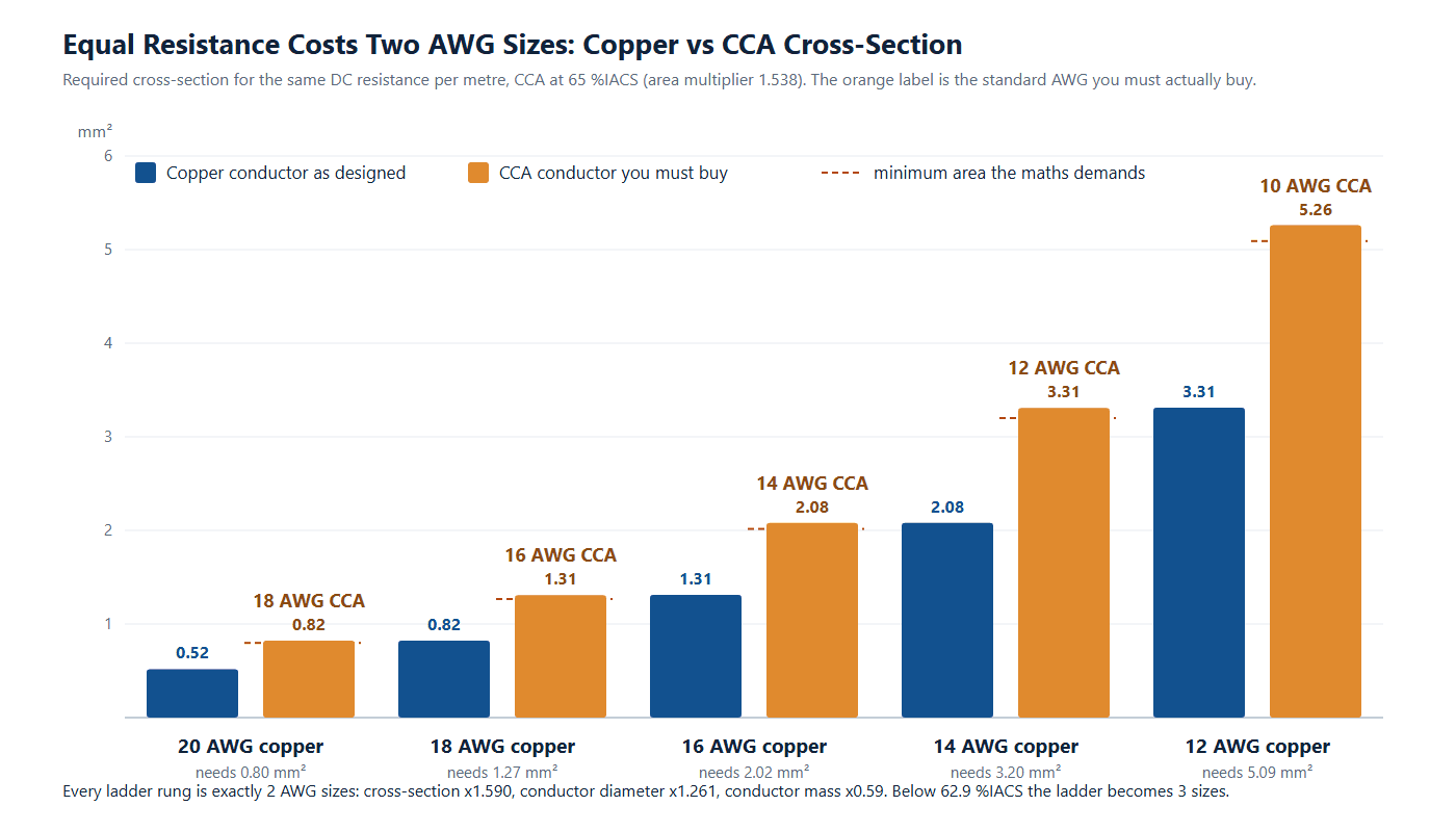
Now convert that area multiplier into AWG steps. Each size step multiplies area by 1.261. Two steps multiply by 1.590, three by 2.005. Compare those against the requirement and something sharp falls out.
| CCA conductivity | Required area multiplier | AWG sizes to add | Margin at that step |
|---|---|---|---|
| 70 %IACS | ×1.429 | +2 | +11.3 % |
| 68 %IACS | ×1.471 | +2 | +8.1 % |
| 66 %IACS | ×1.515 | +2 | +4.9 % |
| 65 %IACS | ×1.538 | +2 | +3.3 % |
| 64 %IACS | ×1.563 | +2 | +1.8 % |
| 63 %IACS | ×1.587 | +2 | +0.2 % |
| 62 %IACS | ×1.613 | +3 | +24.3 % |
| 60 %IACS | ×1.667 | +3 | +20.3 % |
The threshold is 62.9 %IACS. Above it, two size steps are enough. Below it, you need three. Note how thin the margin is at 63 %IACS: 0.2 %. The popular rule “go up two gauges” therefore has almost no reserve, and one rounding of the stranding factor or one optimistic data-sheet figure consumes it.
Table 3 turns that into the ladder you will actually use on a real build.
| Copper design | Copper area (mm²) | Required CCA area | CCA size to buy | CCA area (mm²) | Diameter |
|---|---|---|---|---|---|
| 24 AWG | 0.205 | 0.315 | 22 AWG | 0.326 | ×1.261 |
| 22 AWG | 0.326 | 0.501 | 20 AWG | 0.518 | ×1.261 |
| 20 AWG | 0.518 | 0.796 | 18 AWG | 0.823 | ×1.261 |
| 18 AWG | 0.823 | 1.266 | 16 AWG | 1.309 | ×1.261 |
| 16 AWG | 1.309 | 2.013 | 14 AWG | 2.081 | ×1.261 |
| 14 AWG | 2.081 | 3.201 | 12 AWG | 3.309 | ×1.261 |
| 12 AWG | 3.309 | 5.090 | 10 AWG | 5.261 | ×1.261 |
A worked example at a realistic assembly length
Take a 24 V, 3 A power lead, 5 m one way, 3 % budget. That allows 24 Ω/km per conductor at working temperature. Our DC power cable and barrel plug selection guide uses the same budget method, and the conductors it lands on look like the 14 AWG DC barrel pigtail cable, the DC plug XT60 cable in 14 AWG silicone and the 14 AWG DC7909 solar extension cable.
| Conductor | R at 20 °C | R at 70 °C with k | Loop drop | Share of budget | Verdict |
|---|---|---|---|---|---|
| 16 AWG copper | 13.2 Ω/km | 17.8 Ω/km | 0.535 V | 2.23 % | Pass |
| 16 AWG CCA (65 %IACS) | 20.3 Ω/km | 27.4 Ω/km | 0.822 V | 3.43 % | Fail |
| 14 AWG CCA (65 %IACS) | 12.7 Ω/km | 17.2 Ω/km | 0.517 V | 2.16 % | Pass |
Same AWG, same insulation class, same length: the CCA version exceeds a budget the copper version meets. The fix is not a tweak but a jump to a different conductor size. The same arithmetic applies to a fused 12 V distribution harness, a COB LED power injection cable, a 12/24 V cigarette lighter power cable or an IP67 DC to USB-C cable in the 0.5 to 5 m range.
Skin Depth: The High-Frequency Argument Fails at 50/60 Hz
The most persistent claim in the cca vs copper cable literature is that CCA has a high-frequency advantage because current crowds into the copper skin. The claim is physically correct and almost always irrelevant, because nobody checks the frequency at which it becomes true.
Skin depth is the depth at which current density has fallen to 1/e of its surface value: for copper 9.35 mm at 50 Hz and 8.53 mm at 60 Hz, for aluminum 11.6 mm and 10.6 mm. Compare that with a cable assembly: a 20 AWG conductor has a radius of 0.41 mm, a 14 AWG conductor 0.81 mm, even a 4 mm-diameter power conductor 2 mm. At mains frequency skin depth is four to twenty times the conductor radius, so current uses the whole cross-section, aluminum core included, uniformly.
Put the crossover frequencies on the same scale and the picture gets uncomfortable. Copper skin depth equals a 2 mm conductor radius near 1.1 kHz, a 1 mm radius near 4.4 kHz, a 0.51 mm radius near 17 kHz. The copper layer of a 10 %-volume CCA conductor of 2 mm diameter is only about 51 μm thick, and skin depth falls that low only near 1.7 MHz.
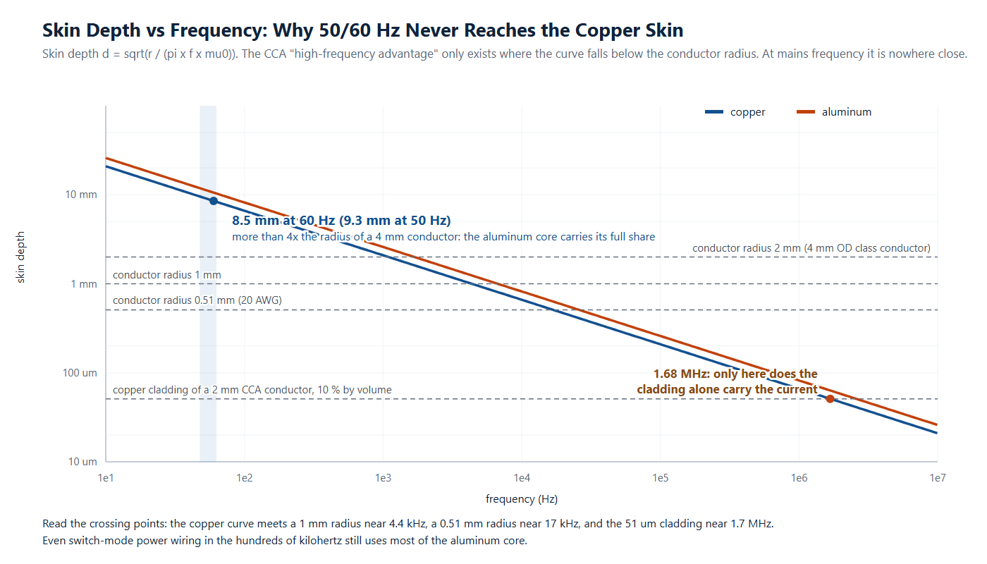
Two honest conclusions. First, at 50/60 Hz and at the few hundred kilohertz typical of switch-mode power conversion, the aluminum core carries its full share of current and the copper layer contributes almost nothing electrically; the high-frequency argument is false for any power application. Second, one place the claim does hold: above roughly 2 MHz skin depth is inside the copper layer, which is why coaxial and RF feedline center conductors are the one application where CCA is a first-choice material. That is an argument about megahertz, not power leads.
Judge power conductors by resistance and data conductors by impedance and return path: our Cat5e vs Cat6 vs Cat6a comparison, the USB-C cable versions and Power Delivery guide, and for the RF exception the SMA to BNC RF coax patch cable, 12G-SDI coax cable assembly and SDI BNC cable assembly pages.
Terminations: Cold Flow, Oxide Film and Galvanic Corrosion
Electrical arguments about cca vs copper cable resolve in months. Mechanical ones take years, and they produce the field failures. Four separate mechanisms act on a CCA termination, none of them present in a copper termination of the same design.
Cold flow. Aluminum creeps under sustained clamping pressure. A correctly torqued terminal relaxes over months as metal flows away from the high spots; joint resistance rises, the joint heats, and the heat accelerates the flow. This is the classic aluminum-wiring failure mode and the reason aluminum-rated hardware has larger contact area and heavier spring follow-up than copper hardware.
Oxide film. Exposed aluminum grows an oxide layer within moments of being abraded. Aluminum oxide is hard, adherent and electrically insulating. Where the cladding is intact the problem is deferred rather than solved: nick the copper skin and the core starts oxidizing at the scratch.
Galvanic corrosion. Copper and aluminum sit far apart in the galvanic series. Add moisture as an electrolyte and the aluminum becomes the sacrificial electrode. A joint dry inside a cabinet is fine; the same joint in an outdoor enclosure or washdown area is a small battery.
Thermal expansion mismatch. Aluminum expands at 23 × 10-6/K against 16.7 for copper, so every thermal cycle works the interface: in a screw terminal it pumps the conductor, in a crimp it fatigues the contact line.
| Requirement | Mechanism controlled | Without it |
|---|---|---|
| Terminal listed and marked AL/CU | Cold flow, contact area, spring follow-up | Loosening, hot spot at the barrel |
| Oxide-inhibiting compound at the joint | Oxide film, galvanic attack | Unstable contact resistance from day one |
| Written torque value and re-torque interval | Cold flow relaxation | Silent, invisible degradation |
| No copper-only crimp barrels | Cold flow, expansion mismatch | Barrel loosens through thermal cycling |
| Sealed copper-to-aluminum transition joints | Galvanic corrosion in moisture | Aluminum consumed as the sacrificial electrode |
The connector standard governing these requirements is UL 486A-486B, and the installation-side rule in the US National Electrical Code is that connectors must be marked for the conductor material used (NFPA 70, National Electrical Code). Ask what marking a supplier terminals carry before accepting a CCA design. Where the termination is a sealed circular interface rather than a lug, our M12 connector coding guide and overmolded cable design checklist cover the geometry.
Standards, Compliance and the Bending Question
Standards coverage is the quietest and most decisive part of the decision, because it is the one you cannot engineer around. IEC 60228 classifies conductors and sets maximum resistance per class, and its scope states that the conductors it covers “include solid, stranded and Milliken, copper, aluminum and aluminum alloy conductors in cables for fixed installations and flexible copper conductors” (IEC 60228:2023, Conductors of insulated cables). Two things follow.
- The flexible classes in IEC 60228 are copper classes. A claim that a CCA conductor is a “Class 5 equivalent” has no resistance value in that standard to check against.
- The fixed-installation classes recognize copper, aluminum and aluminum alloy as separate materials. Copper-clad aluminum is not one of them, so a CCA conductor is not automatically covered by a copper conductor’s compliance.
In North America the equivalent question is asked by the listing system: a cable is listed for a stated conductor material, and substituting another voids the listing even when the gauge is unchanged. Our automotive wire harness selection guide and wire harness drawing checklist for OEM buyers treat conductor material as a drawing-controlled attribute, as do high-energy builds such as an energy storage cabinet harness, a BESS battery wiring harness, an EV high voltage harness and a railway rolling stock harness.
Then there is bending. Aluminum has lower fatigue strength and lower elongation than copper, and CCA adds a thin, stiff copper skin over a soft core. Under repeated bending the skin cracks first, the exposed aluminum at the crack oxidizes, and the resistance of the conductor and its terminations climbs. This is why CCA and continuous flex do not mix: our guides on continuous flex drag chain cable and bend radius, pull force and routing treat material and stranding as the primary levers on flex life.
The Double Constraint: Equal Resistance Plus Equal Termination Has No Solution
This is the part generic cca vs copper cable articles do not write, because it holds two requirements at once instead of one.
Most cable assembly RFQs arrive with the connector already chosen. The crimp barrel has a published wire window, the clamp, gland and overmold are dimensioned for a diameter, and the bend envelope is set by the mechanism. Termination hardware is fixed before the conductor material is discussed. Add the equal-resistance requirement from Table 2 and the constraint set closes: equal resistance needs 1.590 times the copper cross-section, 1.261 times the diameter, and that breaks three hardware constraints at once.
- Crimp barrel window. The terminal accepts a stated wire range. Your copper design point needs 59 % area headroom above it for the same barrel to take the CCA conductor. Where it does not, you are buying a different terminal, crimp nest and crimp-height and pull-off validation.
- Cable clamp and gland range. Conductor diameter grew 26 %, and with it the cable OD. If the clamp or gland was sized close to the copper cable, the CCA cable falls outside its range: a new overmold and new sealing hardware.
- Bend envelope. Minimum bend radius scales with diameter, so it grows 26 % too. In a drag chain the inner radius is fixed by the chain, so the extra radius cannot be absorbed; it becomes higher conductor strain and shorter flex life.
There is no third option. You cannot keep the same AWG, because Table 4 shows the drop going from 2.23 % to 3.43 %. You cannot keep the same terminal and clamp, because the conductor no longer fits. The constraint set “equal resistance, unchanged termination hardware, unchanged envelope” has no feasible point. Something gives, and in a finished assembly it is usually the schedule and the requalification. Motion builds fail hardest: a custom industrial robot wire harness, a cobot arm harness with drag-chain jacket, a custom servo motor cable assembly or an encoder feedback cable has no room for a 26 % larger conductor.
Where CCA genuinely works
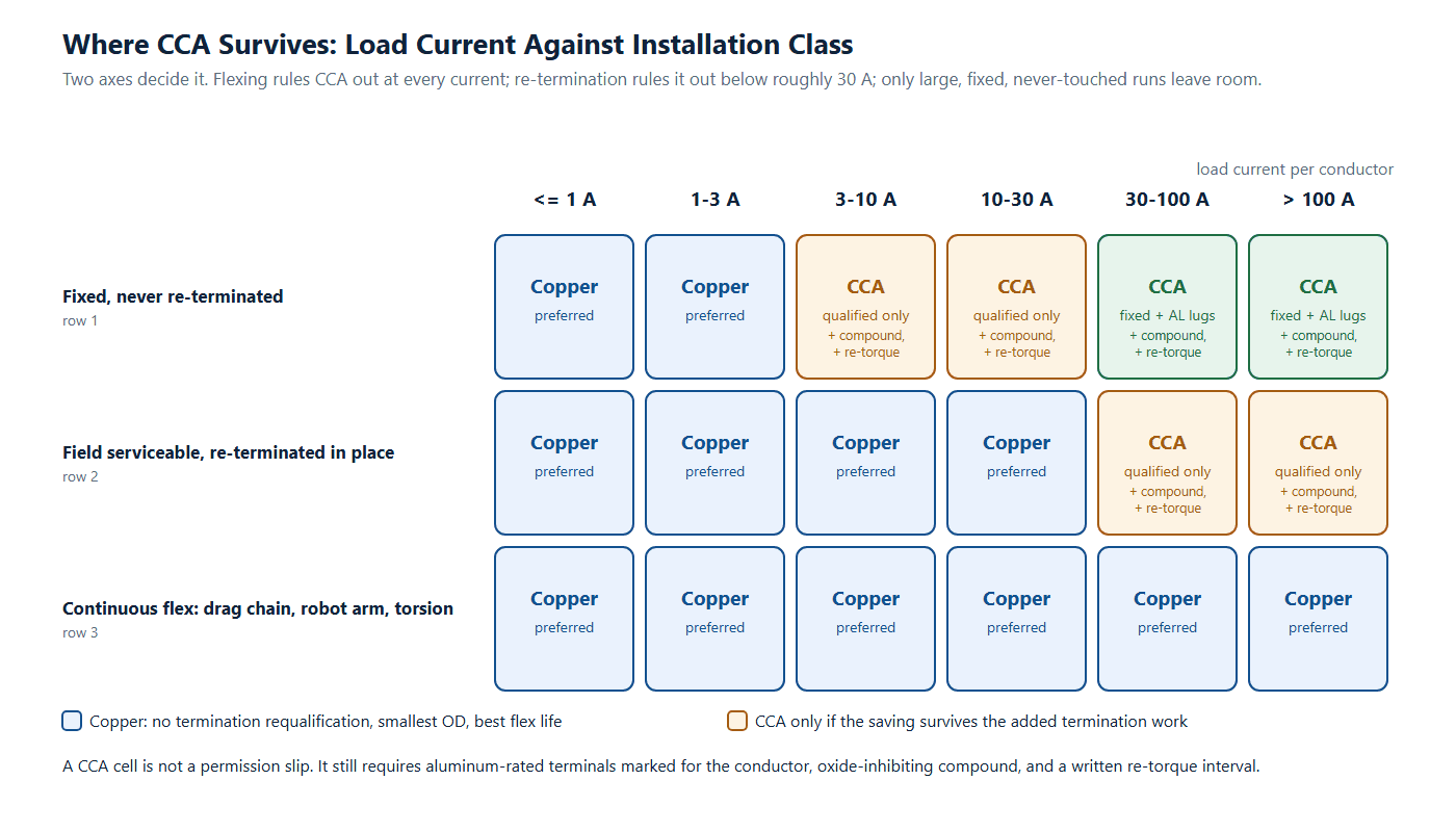
Nothing above says CCA is a bad material. It says the window is narrow, and worth stating precisely. CCA is the right choice when all of the following hold at once:
- The cross-section is large, so the added diameter is small relative to the cable and the hardware.
- The installation is fixed and will never be re-terminated in the field.
- Terminals are aluminum-rated and marked for the conductor, with oxide-inhibiting compound applied.
- There is a written torque value and a re-torque interval.
- The specification is written in Ω/km so resistance, not gauge, is the contract quantity.
- Weight, not cost, is the driver: at equal resistance the conductor metal is about 59 % of the copper mass, which matters in airborne and portable builds such as a lightweight UAV wire harness.
RF feedline and coaxial center conductors sit in their own category for the skin-depth reason above. Everything else — small-gauge power leads, re-terminatable field cable, anything in a motion axis — belongs to copper.
The cost lines that actually move
Money only makes sense after the engineering, and it is a matter of which quantities recur. Metal prices move weekly, so Table 6 gives quantities to multiply by your own quotes rather than a number that will be wrong by the time you read it.
| Cost line | Copper baseline | CCA at equal resistance | Direction | How to quantify |
|---|---|---|---|---|
| Conductor metal mass | 11.7 g/m (16 AWG) | 6.9 g/m (14 AWG) | Down 41 % | Mass × price per kg |
| Conductor diameter | 1.00 | 1.261 | Up 26 % | Jacket compound scales with OD |
| Minimum bend radius | 1.00 | 1.261 | Up 26 % | Larger chain, larger service loop |
| Termination hardware | Standard copper crimp | AL-rated lug, compound | Up | Terminal price × count |
| Requalification | None | New crimp height, pull-off, thermal cycle | Up, one-off | Lab time plus tooling |
| Field service risk | Any qualified technician | Compound and re-torque discipline | Up, recurring | Service visits over the life |
| Shipping and handling | 1.00 | Conductor share × 0.59 | Down | Freight weight × rate |
The savings are commodity quantities: metal mass and freight. The costs are engineering and service quantities: requalification, termination discipline, flex life. On a large fixed run the engineering cost is paid once and the metal saving every meter, which is where CCA belongs. On a small flexible assembly the costs recur and the saving is measured in grams.
How to Write a Purchase Specification That Actually Protects You
Every point above collapses into one procurement habit. AWG and nominal cross-section describe geometry; resistance per unit length describes performance, and it is the only one that can be measured on the finished cable and accepted or rejected. That is why the same gauge never means the same ampacity once the material changes: a gauge number hides the resistivity, and resistivity is what heats the cable.
| Specification line | Write this | Not this |
|---|---|---|
| Conductor resistance | Maximum Ω/km per conductor at 20 °C, measured on the finished cable | Nominal AWG or mm² |
| Conductor material | Bare annealed copper, Class 5 stranded, IEC 60228 | “Copper” with no class |
| CCA, if intended | Copper-clad aluminum, stated copper volume class, maximum Ω/km | “CCA equivalent” or a bare %IACS figure |
| Termination | Terminals marked for the conductor material, stated barrel window, compound and torque | “Standard crimp” |
| Flex class | Continuous flex, stated minimum bend radius, cycles per bench data | “Flexible” |
| Verification | 100 % resistance screening, or a stated AQL with a report | “Certificate on request” |
HKWIRE builds to specified conductor material and specified resistance, and we will tell you plainly when a material substitution costs more than it saves. Browse our DC plug power cable, custom wire harness and signal and data cable ranges, or send us the drawing.
Have a cca vs copper cable decision on a live build?
Send HKWIRE the length, the current and the connector. We return the resistance budget, the conductor recommendation and the termination requirement with the quote, before you commit to a material.
FAQ: CCA vs Copper Cable
Is CCA a direct substitute for copper cable of the same gauge?
No. At the same gauge, copper-clad aluminum has roughly 1.5 to 1.7 times the DC resistance of copper, depending on copper volume fraction. In the worked example above, the same 16 AWG conductor pushed a 5 m, 24 V, 3 A run from 2.23 % drop to 3.43 %. Equal resistance needs about two more AWG sizes, and only at or above 62.9 %IACS.
Does CCA have a high-frequency advantage over copper cable?
Only well above mains and switching frequencies. Skin depth in copper is about 8.5 mm at 60 Hz, far larger than any conductor in an assembly, so the aluminum core is fully used and contributes nothing. The copper layer carries the current alone once skin depth falls below the cladding thickness, near 1.7 MHz for a 2 mm conductor with 10 % copper volume. RF and coaxial center conductors are the legitimate case; power leads are not.
Why does the same AWG CCA cable run hotter than copper?
Because heat is current squared times resistance, and resistance is higher at the same gauge. In a bundle the heat has nowhere to go, so the bundle runs hotter and consumes insulation temperature rating faster. Any ampacity figure for CCA must come from that manufacturer data, not a copper table.
What terminals can be used with copper-clad aluminum conductors?
Terminals listed and marked for aluminum or dual-rated AL/CU, applied with oxide-inhibiting compound, a stated torque value and a re-torque interval. Copper-only crimp barrels are not acceptable. UL 486A-486B governs the connectors and NFPA 70 the marking rules.
Can CCA be used in a drag chain or on a robot arm?
No. Aluminum has lower fatigue strength than copper and the thin copper skin cracks first under repeated bending. Once it cracks, the exposed core oxidizes and the resistance of the conductor and its terminations rises. Continuous flex belongs to copper, and stranding choice matters most.
Is CCA cheaper than copper cable once the build is finished?
The conductor metal is cheaper, and at equal resistance the CCA conductor is about 59 % of the copper mass. Missing from most comparisons is the cost of being two AWG sizes larger: more jacket compound, a larger bend radius, different termination hardware and a crimp requalification. On large fixed runs the metal saving dominates; on small flexible assemblies the requalification does.
What single number should I ask a CCA supplier for?
Maximum ohms per kilometer per conductor at 20 °C, measured on the finished conductor. Conductivity percentages, copper volume fractions and gauge equivalences are inputs to a calculation you should not have to perform. Resistance per unit length is what your drop budget, heating budget and acceptance test all use.
For more selection guides see our audio and video cable and Ethernet patch cord categories, plus the XLR microphone cable and balanced IEM cable pages for shielded low-level runs.







