

A drag chain cable is not a flexible cable with a tougher jacket. It is a different conductor construction, sold against a test curve rather than a catalog page, and it fails for reasons that have nothing to do with current. When an axis moves, the copper inside is bent and straightened millions of times a year, and the part that dies first is the individual copper strand. If you are choosing a drag chain cable for a machine that must run for years, the decision that matters most is the one most selection guides never mention: how thin the strands are.
This guide covers the five variables that set service life, then spends most of its length on the strand-diameter calculation that turns “flex rated” into a number you can check. Every figure below is calculated from published standards and cable-maker data, which is also how HKWIRE quotes flexible cordsets.
1. Define the motion profile first
Before you pick a part number, quantify the motion. Service-life ratings are only comparable if they describe the same motion, and the same cable can appear as four million cycles in one catalog and twenty million in another purely because the test rigs differ. Record five things:
- Travel distance — the stroke length inside the carrier.
- Bend radius — the smallest radius the cable sees, almost always at the carrier’s fixed and moving ends.
- Twist or torsion — rotary and three-dimensional motions need a dedicated torsion-rated construction.
- Cycle rate — strokes per minute, hours per day, days per year.
- Acceleration — high acceleration raises the peak tensile load on conductor and boot.
The cycle-rate arithmetic is where specifications go wrong, because the numbers are small as a rate and enormous as a lifetime. A double stroke is one complete out-and-back travel of the carrier, which is the unit cable makers use:
| Axis duty | Rate | Hours/day | Days/year | Double strokes/year | 10 million reached in |
|---|---|---|---|---|---|
| Light indexing axis | 6/min | 8 | 250 | 720,000 | 13.9 years |
| Typical pick and place | 12/min | 16 | 250 | 2,880,000 | 3.5 years |
| Continuous rotary indexer | 20/min | 24 | 365 | 10,512,000 | 0.95 years |
Read the last row again. A machine running twenty strokes a minute around the clock consumes a ten-million-cycle rating in under twelve months. Any cycle figure in a datasheet is meaningless until you have done this multiplication.
A rule of thumb circulating widely says to size the bend radius to at least 10 to 15 times the cable outer diameter for chain flex, and about 5 times for torsional flex. The torsional half is close to what some cable makers publish. The linear half has no standard behind it: published series data spans roughly 4 to 14.5 times the diameter, so a fixed rule will either cost you money or cost you a drag chain cable failure.
2. Conductor and stranding
Flex life comes from fine, concentric stranding, not from the insulator. The conductor classes are defined in IEC 60228, the horizontal standard that specifies nominal cross-sectional areas and also sets “requirements for numbers and sizes of wires and resistance values”. Two conductors can both be honestly labeled 1.0 mm² and be entirely different inside:
| IEC 60228 class | Construction | Typical use | Max single wire dia. at 1.0 mm² | Typical wire count |
|---|---|---|---|---|
| Class 1 | Solid, single wire | Fixed installation | — | 1 |
| Class 2 | Stranded | Fixed installation, some bending | 0.43 mm (7 wires) | 7 |
| Class 5 | Flexible | Portable equipment, light flexing | 0.21 mm | about 30 |
| Class 6 | Extra-flexible | Handheld tools, robots, drag chains | 0.16 mm | about 56 |
The maximum-wire-diameter column is the binding part of IEC 60228. The standard caps how thick an individual wire may be for a given cross-section and class, and pairs that with a maximum resistance at 20 °C — 19.5 Ω/km for a 1.0 mm² flexible copper conductor. Wire count is a consequence, not a fixed value, which is why two suppliers quoting “Class 6, 1.0 mm²” can still ship different flex life.
Layout matters as much as count. A bunched conductor has strands in no particular order, so individual strands can be forced to take more than their share of the outer-fiber strain; a concentric, non-spiral lay keeps every layer organized around a center. Shorter lay length generally improves flexibility, and soft filler plus a center support stop the cores collapsing into an oval during a bend, which would pinch the outer cores. Cable-maker technical tables such as this IEC 60228 Class 5 and Class 6 stranding reference are the best place to confirm what a supplier is actually offering.
For signal pairs, specify paired and twisted with individual shields — an overall braid plus a per-pair shield — when noise matters. Our M8 and M12 continuous-flex cordsets use fine-stranded conductors sized for drag-chain duty rather than for a bench-top bend test.
The strand diameter sets flex life, not the outer diameter
Here is the calculation that separates a drag chain cable from a look-alike. Bend a rod of diameter d to a centerline bend radius R. Over a bend angle θ, the centerline follows an arc of length R · θ, while the outermost fiber sits half a diameter further out and follows (R + d/2) · θ. Strain in that outer fiber is the extra length divided by the original:
ε = [ (R + d/2) · θ − R · θ ] / (R · θ) = (d/2) / R = d / (2R)
This is elementary beam bending, the relation that appears in any mechanics-of-materials treatment of a bent beam, and it applies to a copper strand as much as to a beam. What matters is what d means. For the cable as a whole, d is the outer diameter. For the copper inside, d is the strand diameter. Those differ by more than an order of magnitude, and only the second governs fatigue.
Put numbers on it. Take a cable of 10 mm overall diameter in a carrier at eight times that, so R = 8 × 10 = 80 mm. The outer jacket is strained by ε = 10 / (2 × 80) = 6.25% — a level that would destroy solid copper quickly. Each copper strand, however, is strained only by its own diameter:
| Conductor class at 1.0 mm² | Strand diameter | Strand strain at R = 80 mm | Relative to Class 6 | Resistance at 20 °C |
|---|---|---|---|---|
| Class 2 (stranded) | 0.43 mm | 0.269% | 2.69 × | 18.1 Ω/km |
| Class 5 (flexible) | 0.21 mm | 0.131% | 1.31 × | 19.5 Ω/km |
| Class 6 (extra-flexible) | 0.16 mm | 0.100% | 1.00 × | 19.5 Ω/km |
| Jacket outer fiber (10 mm cable) | 10 mm | 6.25% | 62.5 × | — |
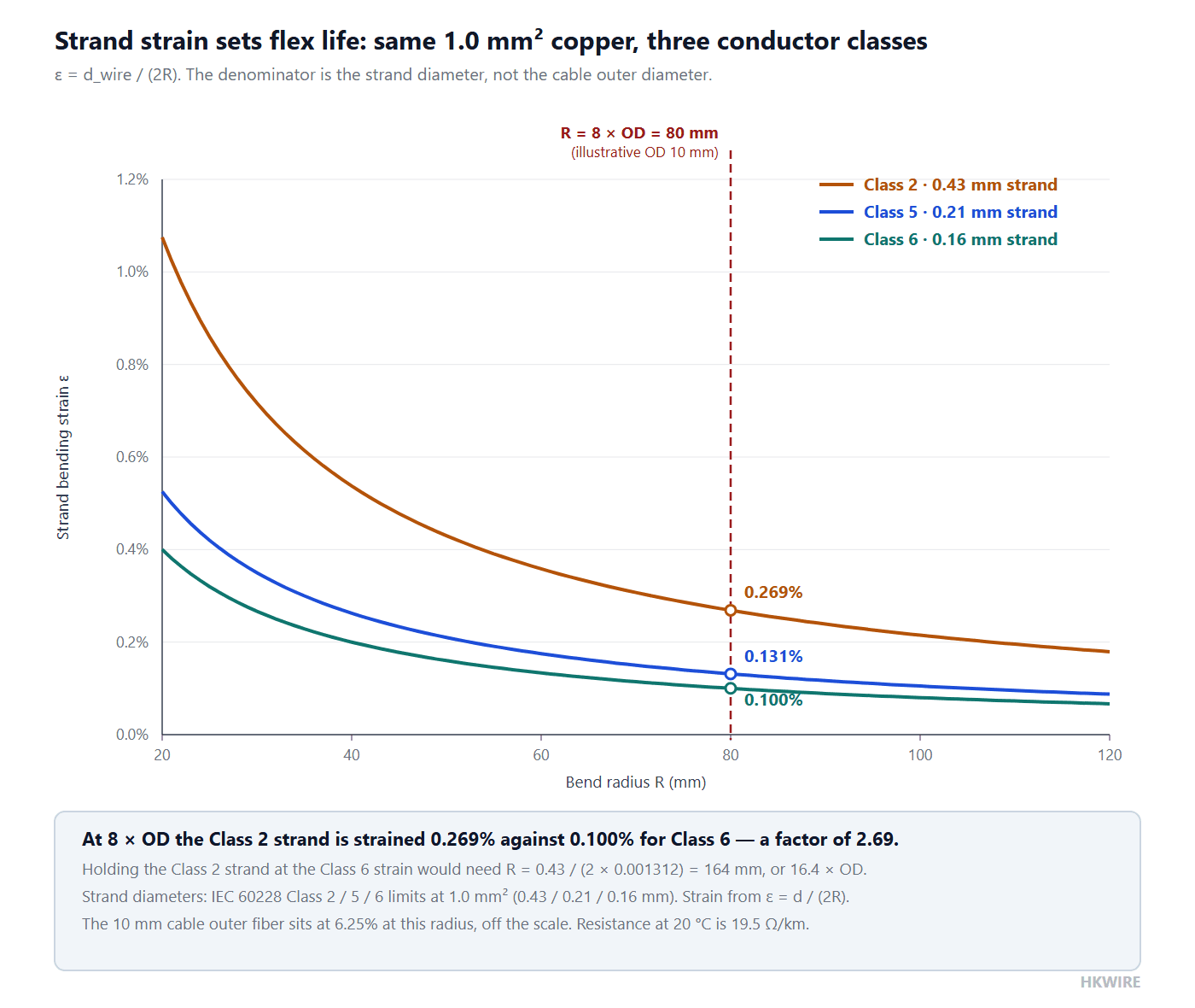
That table is the whole argument in four rows. Three cables sit in the same carrier at the same radius carrying the same copper, and the copper in the Class 2 cable is worked 2.69 times as hard per bend as the copper in the Class 6 cable. Copper fatigue life is driven by strain amplitude, so a factor of 2.69 is the difference between a drag chain cable that lasts a season and one that lasts a decade.
Working the formula backwards
Because the relation is a simple inverse you can also invert it. Suppose a Class 2 stranded conductor is already specified and you want to know what radius it would need to be strained no harder than the Class 5 conductor above, in the same carrier at eight times the diameter. Take that row’s strand strain, 0.1312 % = 0.001312, and set the strains equal:
R = d / (2ε) = 0.43 / (2 × 0.001312) = 164 mm
That is 16.4 times the 10 mm outer diameter. The practical reading is blunt: keep the coarse conductor and you must buy a carrier roughly twice as large to get the copper fatigue life a fine-stranded cable would give you in the smaller one. Re-sizing a carrier is almost always more expensive than re-specifying the cable.
Strain is inversely proportional to radius
The same relation explains why halving the radius doubles the strain, the most counter-intuitive part of drag chain selection. Enlarge the radius from eight times the diameter to ten and then twelve and a half, and the Class 6 strand strain falls in exact proportion: 0.100% at 80 mm, 0.080% at 100 mm, 0.064% at 125 mm. Doubling the radius halves the strain. That linearity is why a carrier one size larger than you first thought so often pays for itself, and why “we will just bend it a little tighter at the end” is the most expensive sentence in machine design.
Bend radius for a drag chain cable: every source on the same cable
Once you accept that the radius is the denominator of the strain, the next question is what number to use. This is where the field is most confused, because four numbers with four different scopes get quoted as if they were interchangeable. Put them on one scale — an 8 mm cable — and the disagreement appears:
| Source | Scope it is written for | Factor | Radius on an 8 mm cable |
|---|---|---|---|
| TIA-568-C.0 §5.3.2.1 | 4-pair balanced twisted-pair cabling, installed | 4 × OD | 32.0 mm |
| igus chainflex CF9 | Control cable, light to medium duty, moving | 5.0 to 8.5 × d | 40.0 to 68.0 mm |
| igus chainflex CF77.UL.D | Torsion-rated cable, moving | 6.8 to 12 × d | 54.4 to 96.0 mm |
| igus chainflex CF140.UL | Control cable, medium duty, moving | 7.5 to 14.5 × d | 60.0 to 116.0 mm |
| “10 to 15 × OD” rule of thumb | Usually stated with no scope at all | 10 to 15 × OD | 80.0 to 120.0 mm |
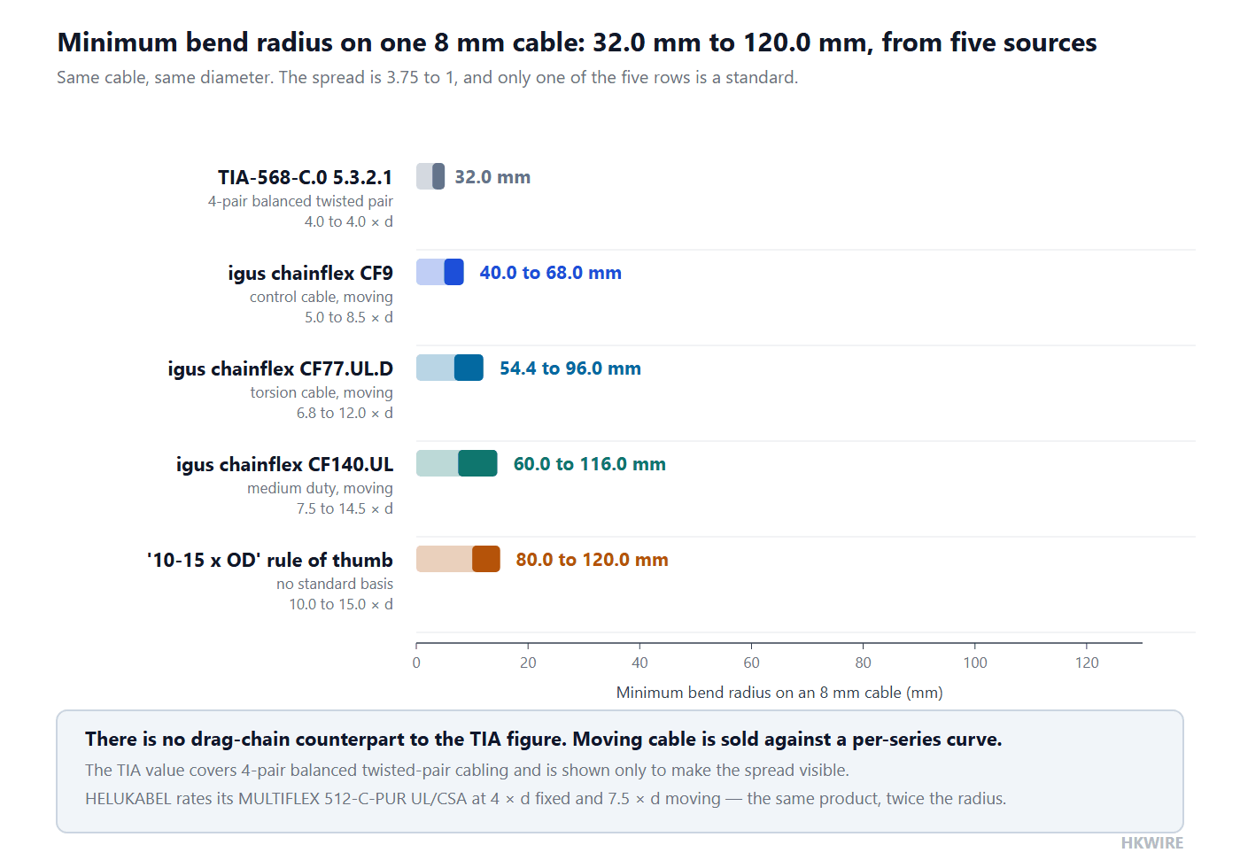
The spread is 3.75 to 1 on the same cable, and two consequences follow.
There is no standard number to appeal to
The only row citing a standard is the TIA row, and it is about structured cabling, not drag chains. For continuously moving cable no equivalent published number exists. What exists is a per-series guarantee table in which the required bend factor depends on temperature, travel length and the number of double strokes you want:
| Operating temperature | Factor for 5 million double strokes | For 7.5 million | For 10 million |
|---|---|---|---|
| −25 °C to +90 °C | 5.0 × d | 6.0 × d | 7.0 × d |
| −35 °C to −15 °C, and +90 °C to +100 °C | 6.8 × d | 7.5 × d | 8.5 × d |
Read across the first row: the same cable needs a 40% larger radius to reach ten million double strokes instead of five. The number is not a property of the cable; it is a property of the cable, the temperature and the lifetime you are asking for, all at once. The published curve in the chainflex guarantee and service-life tables is the final authority, and the only way to use it is to bring your own duty cycle — which is what the cycle-rate table at the top of this article is for. The CF77.UL.D torsion series data shows the same pattern.
Read the guarantee terms, not the headline. igus guarantees chainflex for up to four years or 100 million double strokes, whichever comes first, and Underwriters Laboratories verified that wording — which makes it a usable procurement hook rather than a slogan.
The most common error in this area is quoting a fixed-installation bend radius into a moving application. Those are two different specifications on the same datasheet, and the gap is roughly a factor of two: HELUKABEL rates its MULTIFLEX 512-C-PUR UL/CSA at 4 × d when fixed but 7.5 × d when moving — 32 mm against 60 mm on an 8 mm cable. If the cable moves at all, use the moving figure. For static routing limits, pulling tension and sidewall pressure, see our guide to cable bend radius, pull force and routing.
3. Jacket material for the environment
The jacket is what touches the world and is the second most common reason a drag chain cable comes back. Match it to the abuse and to the temperature the axis actually reaches — the motor end of a carrier is often 20 to 30 °C warmer than the cell. The figures below are nominal service ranges of the kind published in cable-maker material guides, not limits taken from a standard:
| Jacket | Best for | Avoid | Nominal temperature range |
|---|---|---|---|
| PVC | Dry, light-flex, low cost | Oil, continuous flex past a few hundred thousand cycles | −20 to 105 °C |
| PUR (polyurethane) | Oil, coolant, abrasion, continuous flex | Sustained heat above about 80 °C | −55 to 80 °C |
| TPE (thermoplastic elastomer) | Halogen-free, wide temperature, good flex | Sharp cutting edges and drag over burrs | −50 to 105 °C |
| XLPE | Fixed or lightly moving power cores | Very low temperature | −40 to 105 °C |
| EPDM | Outdoor, water, steam-adjacent duty | Mineral oil | −55 to 125 °C |
| FEP | High temperature, chemical exposure | Mechanical abuse — soft and easily cut | −80 to 200 °C |
| PFA | Highest temperature and chemical duty | Cost-sensitive, abrasion-heavy use | −200 to 260 °C |
For most industrial carriers PUR or TPE is right. PUR wins on oil, coolant and abrasion; TPE wins where halogen-free construction, a wider temperature band or a softer feel matters. PVC on a moving axis is a false economy past a few hundred thousand cycles: it stiffens with age and then cracks at the cable entry. See our PVC versus PUR versus TPE jacket guide for the halogen and flame-test side of the comparison.
4. Shielding and pair grouping
Motion generates microphonic noise, and the carrier is usually an electrically noisy neighborhood. For encoder, fieldbus and analog signals:
- Use an overall braid, plus foil where high-frequency noise is present. A braid alone is normally adequate for motor-adjacent digital I/O; foil plus braid is the safer default for encoder feedback.
- Keep power and signal pairs physically separated, or give the signal pairs their own shields. An unshielded analog pair bundled against a power core is a noise source you will chase for months.
- Lay signal and power cables in separate compartments or trays where the chain design allows. This is a mechanical decision too: mixed diameters in one bundle force the smaller cables to migrate, and migration changes the lay and the strain.
- Never use the shield as a strain path. A drain wire carrying tensile load breaks before the conductors do.
For industrial Ethernet the connector format matters more than most buyers expect. A standard RJ45 patch cord is not a drag-chain part, and the comparison between RJ45 and M12 X-coded industrial Ethernet is really about which one survives the chain and the washdown.
5. The connector and strain relief are part of the cable
A flex-rated cable terminated with a rigid, crimp-only connector still fails at the boot. The cable entry is where the bend radius is smallest and the assembly stiffest, so strain concentrates into a few millimeters of jacket. The right termination for a moving axis is an overmolded strain relief that transitions the bend gradually and seals the entry:
- An overmolded boot spreads the bend over its length instead of concentrating it at the backshell. The taper matters more than total length: a long boot that is straight for its first half achieves nothing.
- An IP-rated molded body keeps coolant, chips and washdown water out of the contact cavity. See what to define in an overmolded design for the drawing side of that requirement.
- A screw-lock coupling rather than a latch keeps the connector seated when the axis vibrates, which is why screw-lock molded cordsets are the usual default on moving equipment.
- The strain member belongs inside the molded body. Aramid yarn, a bonded nylon layer or a molded-in collar all work, but only if anchored so pull-out load never reaches the crimp.
One geometric point is easy to miss: the boot is rigid compared with the cable, so its exit is a new and often tighter bend than anything in the middle of the chain. If the panel geometry forces the cable to leave the connector at a sharp angle, no amount of chain sizing will save that drag chain cable. Specify the boot angle to match the way the cable leaves the panel. HKWIRE runs more than 100 in-house mold tools, so boot geometry can be matched to your panel rather than forced into a catalog shape.
Torsion is a different specification, not a bigger bend
A rotary or three-dimensional motion does not flex a cable, it twists it. That is a different load case with its own specification, expressed in degrees per meter rather than as a multiple of diameter — and selecting a torsion application with a bend radius is a routine and expensive mistake. Take the CF77.UL.D torsion cable:
| Requirement | Value | Conditions |
|---|---|---|
| Minimum bend factor, moving | 6.8 × d to 12 × d | 6.8 × d at +15 to +70 °C for 5 million double strokes; rising at low temperature, long travel and 10 million double strokes |
| Maximum torsion, 5 million cycles | ±180 °/m | −15 °C to +70 °C |
| Maximum torsion, 7.5 million cycles | ±120 °/m | −15 °C to +70 °C |
| Maximum torsion, 10 million cycles | ±60 °/m | −15 °C to +70 °C |
| Maximum torsion at temperature extremes | ±30 °/m | −25 to −15 °C and +70 to +80 °C |
Look at the shape of that table. Asking for twice the cycles cuts the allowable twist to a third, and moving to the edge of the temperature range cuts it to a sixth — from ±180 °/m down to ±30 °/m on the same cable. No bend-radius number can express that, which is why “our robot wrist twists about 90 degrees per meter” should immediately end the bend-radius conversation and start a torsion one. The conductor construction differs too, usually with a center support element and an optimized lay.
The chain ends are where the radius really is
Chain makers quote a chain radius, and it is tempting to treat that as the radius the cable sees. It usually is not, because three places are tighter:
- The fixed point at the stationary end, where the cable goes from the chain bracket into the tray or cabinet through a short, tight transition.
- The moving point at the carriage end, where the cable reaches the tool and the last millimeters of travel are often drawn tighter than the chain allows.
- The connector boot, whose rigid exit is a constraint the chain radius says nothing about.
Specify the radius at all three points, take the worst as the design case, and enter the strain formula with it. This is why a tapered overmolded boot earns its cost: it converts a step change in stiffness into a gradient, and a gradient is what the strain formula tolerates.
How to prove flex life: test method, not a catalog number
A real, documented family of bending test methods exists, and using them correctly is the difference between a specification and a wish. The two most quoted rigs are the alternating bending tests with two rollers and with three rollers, defined in DIN EN 50396 §6.2 and §6.3; VDE 0472-603 covers bending behavior in the same family. What these documents define is the method — geometry, rollers, angles. They do not define a pass or fail cycle count, and no ISO or IEC document does either. That number comes from the manufacturer’s own drag chain test rig. A cable maker’s own account of two-roller and three-roller alternating bending tests to DIN EN 50396 shows the split clearly: the rigs and criteria are standardized, the cycle count is not.
So write it that way. Do not demand “10 million cycles to IEC something” — there is no such thing. Demand the drag chain test curve for the series you are buying, at your temperature, travel length and radius, with guarantee terms to match.
The one thing a general article, an AI summary and an online calculator will all get wrong: all of them will tell you the bend radius is a multiple of the cable outer diameter and stop there. That is the wrong denominator. The quantity governing copper fatigue is ε = d_wire / (2R), and d_wire is set by the conductor class — so a 1.0 mm² Class 2 conductor and a 1.0 mm² Class 6 conductor in the same chain at the same radius are strained 2.69 to 1 apart and will not have the same life. Two cables with identical outer diameters and identical printed bend-radius factors are not equivalent drag chain cables. Ask for the strand diameter, not the OD.
Worked example: a 2.88 million double-stroke axis
Put the method together on a realistic axis. A pick-and-place unit strokes 12 times a minute, 16 hours a day, 250 days a year — 2,880,000 double strokes a year. The designer has drawn a 1.0 mm² four-core cable of 10 mm overall diameter into a carrier of 60 mm radius, and asked for ten million double strokes.
- Lifetime check. 10,000,000 ÷ 2,880,000 = 3.5 years. That is the design interval, not a warranty period.
- Radius in diameters. 60 ÷ 10 = 6.0 × OD — inside the range some control cables achieve, but only near the bottom and only at moderate temperature.
- Class 6 strand strain.
ε = 0.16 / (2 × 60) = 0.133%. - Same axis with a Class 5 conductor.
ε = 0.21 / (2 × 60) = 0.175%— 1.31 times the strain for the same motion. - What a Class 2 conductor would need.
R = 0.43 / (2 × 0.00133) = 162 mm, or 16.2 × OD. - Enlarging the radius. Moving the carrier from 60 mm to 80 mm drops the Class 6 strain from 0.133% to 0.100%, a 25% reduction, for the price of one carrier size.
Step six is the one to take to a design review. On a system with a 3.5-year life target, a 25% cut in copper strain for the cost of a slightly larger carrier is usually the cheapest reliability improvement in the machine.
Common mistakes
- Buying “flexible” PVC and expecting ten million cycles. The conductor class, not the word on the reel, sets the life.
- Quoting a fixed-installation radius into a moving application. The two figures differ by roughly a factor of two.
- Twisting the cable inside the carrier to take up slack. Even a small imposed twist changes the lay and removes the life the conductor was designed for.
- Skipping the strain relief and trusting the crimp alone. The crimp is an electrical joint, not a structural one.
- Accepting a cycle number without asking what radius, temperature, travel length and strand diameter produced it.
How we help
If you have a motion profile — travel, radius, cycle rate, temperature and environment — we can specify a continuous-flex cordset with the right conductor class, the right jacket and an overmolded boot matched to your panel, then supply a sample for your own carrier test. Start from our M8 and M12 motion cables or open a custom build through custom development.
Frequently asked questions
What bend radius do I need for a drag chain cable?
There is no single standard answer. Published moving-application figures for one 8 mm cable span 40 mm to 116 mm depending on series and required life. Use the cable maker’s curve for your temperature, travel length and cycle count, and remember the radius at the fixed and moving ends is usually tighter than the nominal chain radius.
Why does strand diameter matter more than outer diameter?
Because bending strain is d / (2R), and for the copper inside a cable the relevant d is the strand diameter. At 1.0 mm² the IEC 60228 ceiling is 0.21 mm for Class 5 and 0.16 mm for Class 6, against about 0.43 mm for a Class 2 stranded conductor — a 2.69 to 1 spread in the same carrier.
Is PUR better than PVC for continuous flex?
Past a few hundred thousand cycles, or with any oil or abrasion exposure, yes. PVC stiffens with age and cracks at the cable entry. PUR and TPE stay elastic far longer; TPE is usual when halogen-free construction or a wider temperature band is required.
Do I need an overmolded connector for a moving axis?
Strongly recommended. The molded boot replaces the step change in stiffness at the backshell with a taper, which is what the strain formula wants, and it seals the cable entry — the most likely point of failure on a moving axis.
Can a standard Ethernet patch cord go in a drag chain?
Not reliably. Use a flex-rated industrial Ethernet cordset, for example an M12 X-coded one. Our M12 X-coded versus RJ45 comparison covers that decision.
What test standard proves flex life?
None proves it alone. DIN EN 50396 §6.2 and §6.3 define the two-roller and three-roller alternating bending methods and VDE 0472-603 covers bending behavior, but none sets a cycle count. The figure comes from the manufacturer’s drag chain test rig, so require the curve.
How do I specify a cable for a robot wrist that twists?
Specify torsion in degrees per meter, not a bend radius. A torsion-rated cable is quoted with a maximum twist that falls as cycle count and temperature spread rise — one published series allows ±180 °/m for five million cycles at room temperature but only ±30 °/m at the ends of its temperature range.
Does a larger carrier really pay for itself?
Often, yes. Strain is inversely proportional to radius, so going from 8 × OD to 12.5 × OD cuts strand strain by about 36% with no change to the cable — usually cheaper than upgrading the cable or accepting a shorter service interval.







