Choosing a GigE Vision cable is mostly an exercise in resisting two temptations: grabbing an office patch cord because the connector fits, and paying for a rugged jacket while ignoring the two numbers that actually decide whether your images survive — DC loop resistance and shield termination quality. A GigE Vision cable is, electrically, a standard balanced twisted-pair Ethernet channel, so every catalog will tell you it is “just Cat5e or Cat6.” What the catalogs rarely tell you is what happens to inspection data when that channel is 26 AWG instead of 24 AWG, when the shield is drained through a long pigtail instead of a 360° clamp, or when a welder fires up two meters from the dress pack. This guide walks the selection the way an integrator should: channel first, power second, protocol third, then the mechanical and environmental details that decide whether the link is still clean after a year of production.
What a GigE Vision Cable Actually Has to Carry
GigE Vision is a machine vision protocol stack running on ordinary Gigabit Ethernet. The camera and the host exchange control traffic over the GigE Vision Control Protocol and image data over the GigE Vision Stream Protocol, both of which ride on UDP. The physical layer is 1000BASE-T, which uses all four pairs of the channel, and the standard defines a maximum segment length of 100 m. Camera makers restate those requirements in their installation manuals — IDS’s GigE camera connection guide, for example, tells integrators to use Category 5e or better, to insist on a shielded cable, and to keep each segment under 100 m.
Throughput is fixed by the physical layer, not by the camera. One gigabit per second is 125,000,000 bytes per second of wire capacity; after packet overhead, hosts typically see around 115 MB/s of usable image throughput. That is enough for a 2048 × 1088 8-bit camera at roughly 50 fps, and it is the number that makes the protocol arithmetic later in this article possible.
Two consequences follow for GigE Vision cable selection. First, because 1000BASE-T uses all four pairs for data, there are no spare pairs left over for power — Power over Ethernet has to share the same pairs through phantom feeding, which is why conductor resistance matters so much. Second, because the link is a standard Ethernet channel, every cabling parameter you would check in an office network (insertion loss, return loss, crosstalk, DC loop resistance) applies unchanged. The difference is the environment: a vision cable is asked to do all of this next to servo drives, inside a drag chain, or under a washdown nozzle.
If your camera is USB3 or CoaXPress instead of Gigabit Ethernet, the electrical model changes completely and a different CoaXPress machine vision cable assembly or a USB3 Vision camera cable with locking screws is the right part to look at. The rest of this article stays with Gigabit Ethernet.
Category, the 100 m Channel, and the 25 Ω DC Loop Rule
Start with the channel, because everything else builds on it. A compliant channel is the complete end-to-end path: the machine cable at the camera, any bulkhead couplers, the fixed horizontal run back to the cabinet, and the patch cord into the switch. ANSI/TIA-568.2-D and ISO/IEC 11801 define the transmission limits for that path, and one of those limits does double duty for machine vision: the DC loop resistance of each pair in the channel shall not exceed 25 Ω. That figure comes straight from ISO/IEC 11801 Table 16 for Class D and above, and IEEE 802.3 working group documents quote the same ceiling when they specify what PoE needs from the cabling plant: the 802.3bt resistance-imbalance ad hoc records the 25 Ω channel DC loop resistance limit for Category 5e, 6 and 6A, and cites the 802.3at objective written for Class D media with a DC loop resistance no greater than 25 Ω.
DC loop resistance is not the same thing as insertion loss. Insertion loss describes how much signal power the channel absorbs at a given frequency; Fluke Networks puts the Category 5e limit at roughly 22 dB at 100 MHz and Category 6 at a little over 32 dB at 250 MHz. Those limits matter when you are certifying a link. For powering a camera, and for the power budget in the next section, the DC figure is the one that bites.
| Category | Typical conductor | Single-conductor DC resistance at 20 °C | Pair DC loop resistance, 100 m | Meets the 25 Ω channel limit at 100 m? |
|---|---|---|---|---|
| Cat5e | 24 AWG | 84.2 Ω/km | 16.8 Ω | Yes |
| Cat6 / Cat6A | 23 AWG | 66.6 Ω/km | 13.3 Ω | Yes |
| High-flex Cat6A cord | 26 AWG | 135 Ω/km | 27.0 Ω | No — 27.0 Ω exceeds 25 Ω |
Read the last row carefully, because it is the trap in most machine vision builds. High-flex cordsets use fine stranded conductors to survive millions of bend cycles, and 26 AWG is the industry workhorse for that job. A short 26 AWG cordset is fine — at 5 m the loop resistance is only 1.35 Ω. But a 100 m channel built from 26 AWG cannot meet the 25 Ω limit no matter how good the foil and braid are. Fine-stranded cable buys flex life, not reach; when the camera is far away, the long middle of the run should be 23 or 24 AWG solid cable and the flexing ends should be short — that split is what a distance-tolerant GigE Vision cable looks like in practice.
Conductor resistance values are the standard annealed-copper figures tabulated by wire gauge — see the standard tabulated AWG resistance figures — and the conductor constructions themselves are specified in IEC 60228.
PoE on a GigE Vision Cable: One Formula Decides the Length
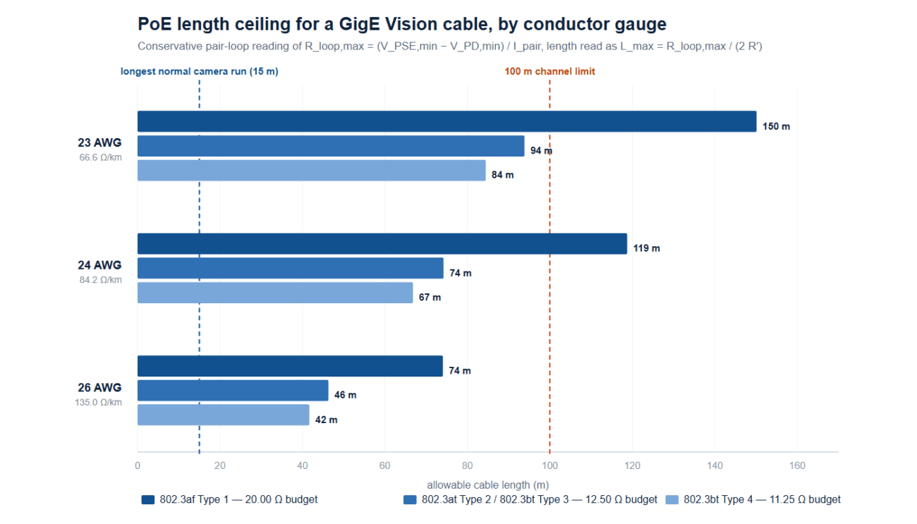
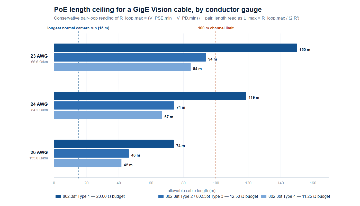
Most machine vision cameras take power over the same cable, and the PoE family is where conductor gauge stops being a footnote. IEEE 802.3 defines four operating types. Each one fixes a minimum voltage the power sourcing equipment (PSE, usually the switch or injector) must deliver, a minimum voltage the powered device (PD, the camera) must still work at, and a maximum current per pair — the same limits Texas Instruments tabulates for 802.3af, 802.3at and 802.3bt powered devices. Subtract the two voltages and divide by the current, and you have the resistance budget for the whole run:
R_loop,max = (V_PSE,min − V_PD,min) / I_pair
R_loop here is the DC loop resistance of a pair — out and back — the same quantity the cabling standards cap at 25 Ω per 100 m channel. Because a pair’s loop resistance is twice the single-conductor figure, the same budget reads directly as a length:
L_max = R_loop,max / (2 R′), where R′ is the single-conductor resistance in Ω/km.
| PoE type | V_PSE,min | V_PD,min | I per pair | Pairs powered | Power at PD | R_loop,max | L_max, 24 AWG | L_max, 26 AWG |
|---|---|---|---|---|---|---|---|---|
| 802.3af (Type 1) | 44.0 V | 37.0 V | 350 mA | 2 | 12.95 W | 20.00 Ω | 119 m | 74 m |
| 802.3at (Type 2) | 50.0 V | 42.5 V | 600 mA | 2 | 25.5 W | 12.50 Ω | 74 m | 46 m |
| 802.3bt (Type 3) | 50.0 V | 42.5 V | 600 mA | 4 | 51 W | 12.50 Ω | 74 m | 46 m |
| 802.3bt (Type 4) | 52.0 V | 41.2 V | 960 mA | 4 | 71.3 W | 11.25 Ω | 67 m | 42 m |
The operational limits in the first five columns are the ones Texas Instruments publishes for powered-device design, and the resulting 20 Ω and 12.5 Ω budgets for Type 1 and Type 2 match the power-loop allotments IEEE itself publishes. Notice the pattern that surprises most engineers: the lowest-power type tolerates the longest thin-gauge cable, because 802.3af was written to survive old Category 3 plant while 802.3bt pushes almost ten times the power through a similar resistance budget.
Why this reading is deliberately conservative. Phantom powering feeds DC onto the transformer center tap, so the two conductors of each pair work in parallel; in four-pair mode two pairsets work in parallel as well. The resistance the current actually sees is therefore lower than the pair loop used above — roughly by half in two-pair modes and by a quarter in four-pair modes. We keep the pair-loop form anyway, for two reasons. It makes the PoE result directly comparable with the 25 Ω channel limit you can measure with a cable certifier, and it leaves margin for the things that eat resistance in a real machine: a conductor at 60 °C inside a bundled drag chain is about 16% higher than its 20 °C rating, and every connector in the channel adds contact resistance on top.
Now put real lengths on the GigE Vision cable. A camera cable is rarely longer than 15 m; dress packs on robots run 3–8 m; cabinet interior patching is 0.5–3 m. The 45 m and 100 m rows below are there for the fixed plant segment between the machine and the panel, which is where PoE problems actually live.
| Run length | R_loop, 24 AWG | Camera voltage, 802.3at / bt Type 3, 24 AWG | Camera voltage, 802.3bt Type 4, 24 AWG | R_loop, 26 AWG | Camera voltage, 802.3at / bt Type 3, 26 AWG | Camera voltage, 802.3bt Type 4, 26 AWG |
|---|---|---|---|---|---|---|
| 1 m | 0.17 Ω | 49.9 V | 51.8 V | 0.27 Ω | 49.8 V | 51.7 V |
| 3 m | 0.51 Ω | 49.7 V | 51.5 V | 0.81 Ω | 49.5 V | 51.2 V |
| 5 m | 0.84 Ω | 49.5 V | 51.2 V | 1.35 Ω | 49.2 V | 50.7 V |
| 8 m | 1.35 Ω | 49.2 V | 50.7 V | 2.16 Ω | 48.7 V | 49.9 V |
| 15 m | 2.53 Ω | 48.5 V | 49.6 V | 4.05 Ω | 47.6 V | 48.1 V |
| 45 m | 7.58 Ω | 42.4 V — fails | 44.7 V | 12.15 Ω | 37.7 V — fails | 40.3 V — fails |
| 100 m | 16.8 Ω | 39.9 V — fails | 35.8 V — fails | 27.0 Ω | 33.8 V — fails | 26.1 V — fails |
Camera-end voltages are computed from the worst-case PSE output (50 V for 802.3at and Type 3, 52 V for Type 4) using the same pair-loop formula. Everything up to 15 m passes with enormous margin, which is the practical takeaway for anyone dressing out a camera head. The failure points are all in the fixed infrastructure: a 26 AWG cord pushed out to 45 m cannot hold 802.3at or Type 4, and even 24 AWG is marginal at 45 m under the conservative reading. If your channel genuinely needs 45 m or more, use 23 AWG cable for the fixed portion and keep the flexible sections short — or power the camera locally and let the cable carry data only.
For the general method of building a voltage-drop budget from load current and run length, see our voltage drop and ampacity cable sizing guide; the arithmetic is identical, only the voltages change.
GVSP Rides on UDP: What One Millisecond of Noise Costs in Image Lines
Here is the section that generic selection guides skip, and it is the reason shielding quality belongs in a buying decision rather than on a datasheet line item. GigE Vision was built on UDP on purpose: UDP is connectionless, has no handshake, and lets a camera stream at line rate with minimal overhead. The price is that UDP does not detect or repair loss — Stemmer Imaging lists the inability to detect and correct lost data among UDP’s drawbacks for multi-camera systems. GigE Vision adds an optional packet-resend mechanism on top of it, in which the host notices a gap in the sequence numbers of a frame and asks the camera to send that packet again — but as LUCID Vision Labs points out, resend is not required for GigE Vision compliance, and vendors report that resend requests in an overloaded system can self-amplify into dropped frames rather than fix them.
So the bytes that an interference burst wipes out are not automatically recovered. They either come back late, or they become a torn line, a corrupted row, or an entire rejected frame. You can put a number on that. At 1 Gbps the link carries 125,000 bytes per millisecond. Divide by the bytes in one image line and you get the lines that vanish per millisecond of outage:
| Camera format | Bytes per line | Lines lost in 0.1 ms | Lines lost in 0.5 ms | Lines lost in 1 ms | Lines lost in 2 ms | Lines lost in 5 ms |
|---|---|---|---|---|---|---|
| 1024 px, 8-bit | 1,024 | 12.2 | 61.0 | 122.1 | 244.1 | 610.4 |
| 2048 px, 8-bit | 2,048 | 6.1 | 30.5 | 61.0 | 122.1 | 305.2 |
| 2048 px, 24-bit RGB | 6,144 | 2.0 | 10.2 | 20.3 | 40.7 | 101.7 |
| 4096 px, 8-bit | 4,096 | 3.1 | 15.3 | 30.5 | 61.0 | 152.6 |
| 8192 px, 8-bit (line scan) | 8,192 | 1.5 | 7.6 | 15.3 | 30.5 | 76.3 |
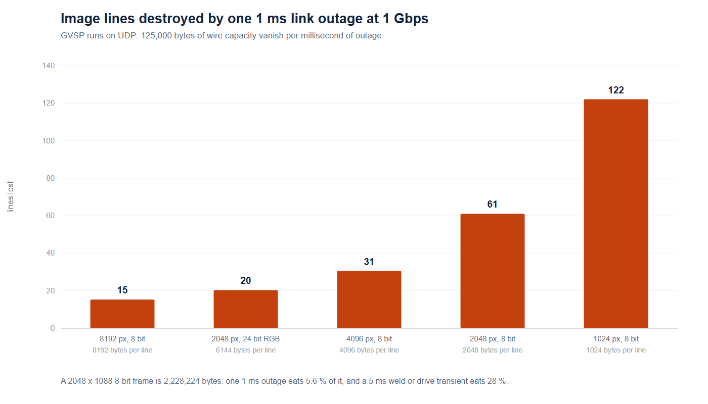
Two things follow. First, the cost of a burst scales with line width, which is why line-scan and 4K area-scan systems are less tolerant of a marginal shield than a VGA inspection camera. Second, the burden of proof shifts from the camera to the channel. A camera can resend a packet only if the packet left the camera and the host has somewhere to put the retry; nothing recovers a bit that was flattened between the RJ45 shells. Shielding and its termination are therefore not comfort features — they are the mechanism that keeps the burst from reaching the pairs in the first place, and the loss table above is what you are buying down when you specify a fully shielded GigE Vision cable with 360° terminations instead of a drain-wire pigtail.
Protocol behavior: GVCP and GVSP run over UDP, and packet resend is an optional feature of the standard — see Stemmer Imaging and LUCID Vision Labs.
S/FTP Versus UTP: Why the Shield on a GigE Vision Cable Ends at the Connector
A shielded cable with a badly terminated shield can perform worse than a good unshielded one, because an unterminated or partially terminated shield turns into an antenna at the very frequencies you were trying to block. Our shielded versus unshielded cable guide covers the general decision; for machine vision the answer is almost always S/FTP — individually foiled pairs plus an overall braid — because the interfering sources on a production floor (servo drives, switch-mode supplies, induction heating, weld controllers) produce strong low-frequency magnetic and electric fields that foil alone does not handle well.
| Construction | Pairs shielded | Overall shield | Pair-to-pair crosstalk inside the cable | Typical machine vision use |
|---|---|---|---|---|
| U/UTP (office patch) | None | None | Relies on pair twisting only | Not recommended near drives or welders |
| F/UTP | None | Foil only | Moderate | Light EMI, short static runs |
| S/FTP | Foiled | Braid over foils | Low — each pair is individually screened | Default for machine vision, robots, cabinets |
The termination is where most of the value is won or lost. The braid and foil must be clamped over a full 360° circumference to a metallic connector shell that then mates with a grounded shell on the camera or switch. A pigtail — a short wire collecting the shield and landing on a pin or a screw — presents inductive impedance that rises with frequency, so the shield that measured beautifully at DC does almost nothing at 100 MHz. When you evaluate a screw-lock or M12 cordset, ask specifically how the braid is captured: crimped ferrule, clamped ring, or loose pigtail. It is the single question that separates a vision-grade assembly from a repackaged office cord, and it is the reason the loss table above is survivable at all.
GigE Vision Cable Jacket and Flex: Fixed Cabinet, Drag Chain, Robot Dress-Out
Once the electrical side is settled, the jacket and the conductor stranding decide whether the cable is still in spec after a year. Match the construction to the motion profile rather than to the marketing word “high-flex”: our continuous flex drag chain cable selection guide walks that decision in detail, and the same logic applies to Ethernet cordsets.
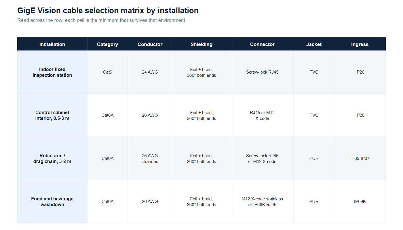
- Fixed runs and cabinet interiors (0.5–3 m). PVC jacket, standard stranding, any category. Nothing moves, so the cheapest compliant part wins — spend the money on the connector instead.
- Occasional motion, gantries and covers. PVC or TPE jacket with finer stranding; the failure mode is chafing at a pass-through, so add a strain relief or grommet rather than a better jacket.
- Drag chains and robot dress packs (3–8 m). PUR jacket over fine-stranded 26 AWG conductors, with a specified bend radius and a flex-life figure the manufacturer will actually publish. Cable carriers chew through PVC jackets; PUR resists oil, coolant and abrasion at the same time.
- Washdown and food plants. PUR again, but the connector becomes the weak point — this is where IP69K-rated couplings with stainless hardware earn their price.
A practical note on length: every meter of the flexing section adds resistance in the PoE table above and adds tensile load on the connector. Keep the moving portion as short as the mechanism allows and put the remaining distance into fixed 23 or 24 AWG cable.
Connector Locking Is an Acceptance Item, Not a Convenience
The last decision is the connector, and it is more than an anti-unplugging device. Three separate engineering problems hide behind the phrase “screw lock,” and they should be verified as three separate acceptance items before a design is released.
Retention. A standard RJ45 latch is a plastic cantilever designed for a handful of insertions in a quiet rack. On a moving axis it is subjected to vibration, cable tug, and the occasional boot — and when the latch snags and releases, the link drops in the middle of a cycle. GigE Vision itself says little about the connector, which is why camera vendors specify locking hardware per camera drawing. A threaded collar pulls the plug square into the jack and holds it there; M12 X-code threading does the same job in a sealed circular shell, and our RJ45 versus M12 X-code comparison covers when each is the better answer.
Fretting. Micro-motion between mating contact surfaces under vibration burns through plating and builds oxide, and contact resistance climbs long before the connection fails outright. On a data pair this shows up as intermittent errors rather than a clean link-down, which is the worst possible failure mode on a vision line because it looks like a software problem. Tin-plated contacts are more fretting-sensitive than gold; where cycles and vibration are high, gold-flashed contacts on the data pairs are worth the premium, and the locking families are compared in our connector locking mechanism selection guide.
Shield continuity. As covered above, the lock is also the mechanical clamp for the 360° shield termination, so retention hardware and EMC performance are the same part.
| Acceptance item | What to verify | Pass criterion | How to check |
|---|---|---|---|
| Retention | Threaded collar fully engaged, no free play, mating geometry matches the camera drawing | No relative motion under a light pull on the cordset | Manual pull and wiggle test after installation |
| Fretting margin | Contact plating type and rated mating cycles | Gold or gold-flash on data pairs where vibration is present | Manufacturer datasheet, then resistance check after 100 mate cycles |
| Shield termination | Braid captured 360° into the shell, not a pigtail | Low-resistance, full-circumference clamp at both ends | Visual on a cut sample plus a shield continuity reading |
| Sealing | IP rating of the mated pair, including the panel side | IP67 for splash zones, IP69K for washdown | Rating certificate plus a mated-pair test, not an unmated plug test |
| Channel test | Full channel certified, not just the fixed cabling | Category pass including DC loop resistance | Cable certifier with the production cordsets in place |
Parts that satisfy all five rows are what a production-grade vision cordset is made of. Our Cat6A S/FTP GigE Vision screw-lock cable for drag chain use and its RJ45 screw-lock GigE Vision cable with high-flex PUR jacket pair 26 AWG S/FTP construction with a crimped shield ferrule and threaded collars on both ends. For sealed heads, the M12 X-code to RJ45 cable in Cat6A S/FTP and the Cat6A M12 X-coded patch cord put the same channel behind an X-coded circular coupling, and the IP69K screw lock cable for RJ45 and M12 gigabit vision links covers washdown lines.
FAQ
Can I use a normal office patch cord instead of a GigE Vision cable?
On a clean bench, at under 3 m, with no PoE and no motion — yes, and many integrators do exactly that during development. On a production machine, no: office cords are UTP, use soft PVC, have an unscreened latch, and their shield (if any) is a cosmetic drain. The failure is usually gradual error counts rather than an immediate link loss, which makes it expensive to diagnose.
Does a GigE Vision cable have to be Cat6A?
No. 1000BASE-T was designed for Category 5e, and a compliant Cat5e channel will carry a 1 Gbps vision link over the full 100 m. Cat6A is chosen for margin (headroom on insertion loss and crosstalk), for future upgrades to 2.5G, 5G or 10GigE, and because industrial Cat6A constructions are almost always the shielded, high-flex ones. Our Cat5e versus Cat6 versus Cat6A guide compares them parameter by parameter.
How long can a GigE Vision cable be?
The Ethernet segment limit is 100 m, and that includes every patch cord and coupler in the channel. In practice, machine vision links are built from a short flexible section at the camera plus fixed cabling back to the panel, and it is the sum of all of it that has to stay under 100 m — and under the PoE resistance budget if the camera is powered over the cable.
Why does my camera lose frames only when a specific machine runs?
That pattern is almost always an interference coupling problem rather than a bandwidth problem. A drive, welder or heater that switches on the same schedule as your lost frames is dumping energy onto the channel, and each millisecond of disturbance destroys roughly 61 lines of a 2048-pixel 8-bit stream. Check GigE Vision cable shield termination quality at both ends first, then routing separation from the offending power conductors.
Does PoE degrade image quality on a GigE Vision cable?
Not if the channel is within its resistance budget. DC power and 1000BASE-T data share the pairs through transformers and do not interfere electrically. The risk is voltage drop: if the loop resistance is too high for the PoE type, the camera sees less than its minimum input voltage and browns out under load — which looks like random camera resets, not like a noisy image.
Are jumbo frames still worth enabling?
Yes. Standard Ethernet frames carry a 1500-byte payload while jumbo frames carry up to about 9000 bytes, so the same image needs roughly six times fewer packets and far less host CPU to reassemble. Beckhoff’s TwinCAT Vision documentation recommends a 9000-byte maximum GVSP packet size, and The Imaging Source gives the same advice for host network cards; every switch in the path must support and be configured for jumbo frames or the larger packets are silently discarded.
What should I send a cable supplier to get the correct GigE Vision cable the first time?
Camera model and connector drawing, whether the camera is PoE powered and at which PoE type, the motion profile (static, occasional flex, drag chain cycles per minute, or torsion), the installed length split between the flexible section and fixed cabling, and the environment (oil, coolant, washdown). A one-page specification with those six items is enough to get an accurate quote instead of a catalog guess.
What is the difference between a GigE Vision cable and a 10GigE cable?
The protocol stack is the same family, but 10GBASE-T needs a channel certified to Category 6A at 500 MHz, and the margin you can afford shrinks sharply with length. For a 10GigE camera, keep runs short, keep the construction S/FTP, and treat the 26 AWG reach limits in Figure 1 as optimistic rather than conservative.
Need a GigE Vision cable that survives your line, not just the catalog?
HKWIRE builds shielded Cat6A vision cordsets with 360° shield terminations, threaded screw-lock couplings and PUR drag-chain jackets — in the length split your machine actually needs. Send us the camera drawing and the motion profile and we will quote a tested assembly, not a guess.