A Kapton insulated cable is the one high-temperature wire that is not extruded. Its insulation is a wound polyimide film — thin tapes of polyimide wrapped over the conductor and fused — rather than a molten plastic that was pushed over the copper and cooled. That single process difference explains almost everything else: the temperature ceiling, the weight, the thin wall, and the specific way a polyimide wire fails at high voltage.
If you are choosing insulation for a run that sees heat, this article gives you the comparison that matters: how Kapton (polyimide) stacks up against PTFE, FEP and silicone on temperature, weight and the real high-voltage limit, which is not the number printed on the datasheet as “dielectric strength.”
What a Kapton insulated cable actually is
The word Kapton is a trademark — originally DuPont, now marketed by Qnity Electronics — for a family of polyimide films. What makes polyimide different from every common insulation is that it does not melt. A thermoplastic like PVC, TPE or FEP softens and flows at a few hundred degrees, so it can be extruded in a continuous molten sleeve around the conductor. Polyimide has a glass transition above roughly 300 °C and chars well above that instead of flowing, so there is no extrusion window to use.
The result is a different construction. A polyimide-insulated wire is built by tape wrapping: layers of film, often 25 µm (1 mil) thick, are wrapped around the conductor and heat-sealed or sintered into place. The military specification MIL-DTL-81381 describes exactly this form — polyimide film tape over silver- or nickel-plated copper, rated 600 V RMS and, depending on plating, 200 °C (silver) or 260 °C (nickel).
Because the wall is stacked from thin tapes rather than poured as one homogeneous layer, the voltage class of a polyimide wire is a structural choice — the number of layers, the overlap and the trapped air between them — not a material property. That distinction becomes the whole story of the high-voltage section below.
The four insulation families, side by side
The table lists typical, indicative values for the four families most often considered for hot wiring. Treat each figure as a starting point: the exact number is set by the grade, the plating and the construction, and the manufacturer’s datasheet is the authority for any specific part.
| Property | Silicone | FEP (UL1331) | PTFE | Polyimide (Kapton) |
|---|---|---|---|---|
| Process | Extruded | Extruded | Paste-extruded, sintered | Film tape, wound |
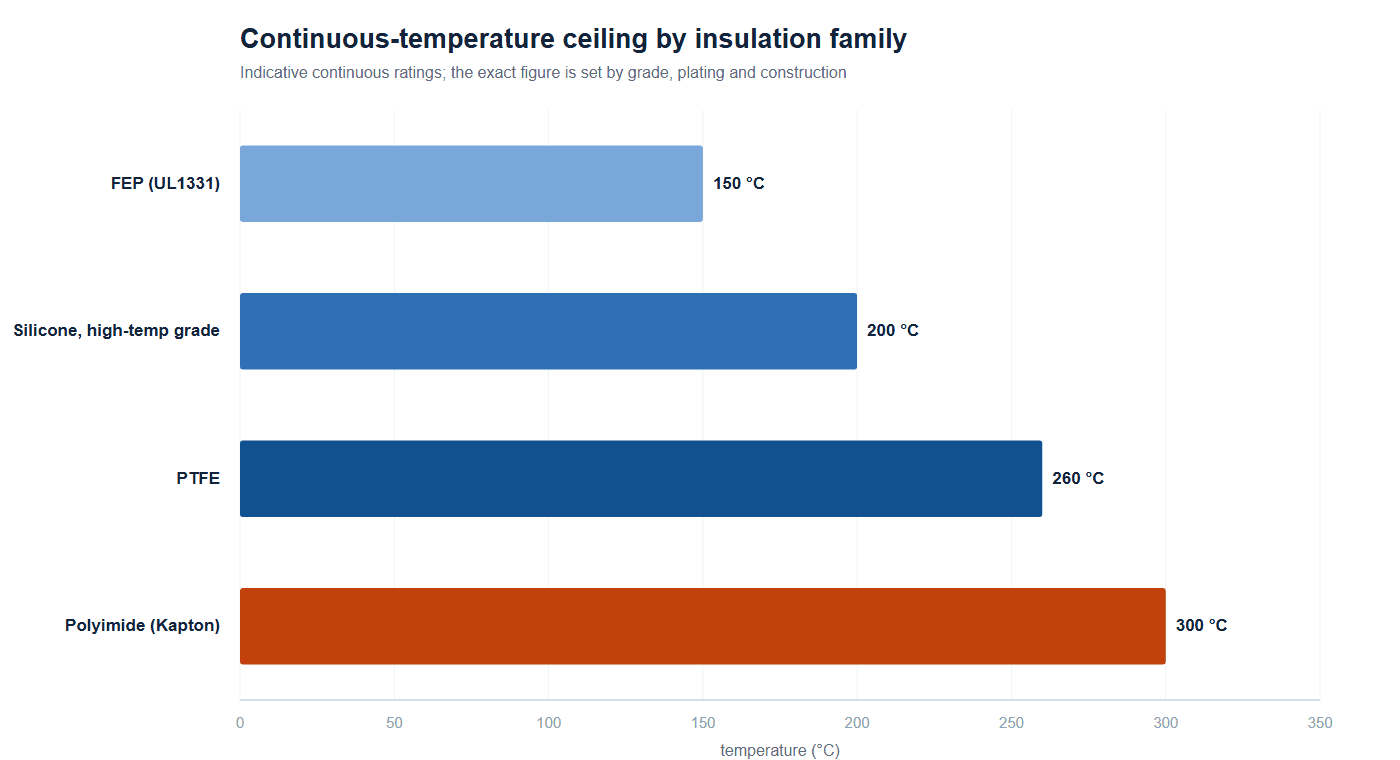
| Continuous temp | −60 to +180 °C (high-temp grade +200 °C) | 150 °C | 200–260 °C | 200–300 °C per grade/plating |
| Typical voltage | 300–600 V | 600 V | 600 V | 600–1,000 V |
| Relative weight | Higher | Medium | Medium | Lowest (thin wall) |
| Flexibility | Excellent | Good | Stiffer | Good, but film is thin |
| Radiation tolerance | Fair | Good | Good | Excellent |
| Low outgassing (vacuum) | Poor | Good | Good | Excellent |
| Relative cost | Low | Mid | High | High |
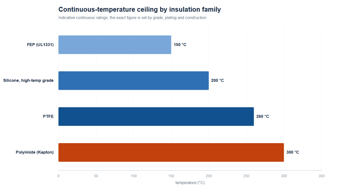
Two columns deserve a closer look because they drive most mis-specifications. First, the temperature ladder — 150 °C FEP, 200 °C silicone high-temp grade, 260 °C PTFE, and 300 °C polyimide — is not a smooth progression of “better.” Each step trades something away, as the next section shows. Second, the voltage column is misleading on purpose: it is where the industry’s real caution lives.
Temperature rating is three different numbers, not one
“Rated 260 °C” sounds like a single, hard fact, but a temperature rating is really three questions with three different answers:
- Continuous operating temperature — the temperature the insulation can live at for its service life without degrading unacceptably.
- Short-term / peak temperature — what it survives for seconds to minutes, such as a solder or reflow excursion.
- UL thermal index (RTI) — the temperature at which a property retains half its original value after a standardized aging study, under UL 746B.
Polyimide is the clearest example of why the three must not be confused. A Kapton-grade film carries a UL electrical RTI around 240 °C but a mechanical RTI around 200 °C — the film keeps insulating long after it has lost enough tensile strength to matter in a flexing harness. A nickel-plated polyimide wire can be specified to 260 °C (or, in radiation-hardened grades, higher), but that is a continuous figure tied to the whole construction, not a license to ignore the mechanical half of the rating. When a spec sheet prints one number, ask which of the three it is.
The high-voltage trap: dielectric strength is not voltage endurance
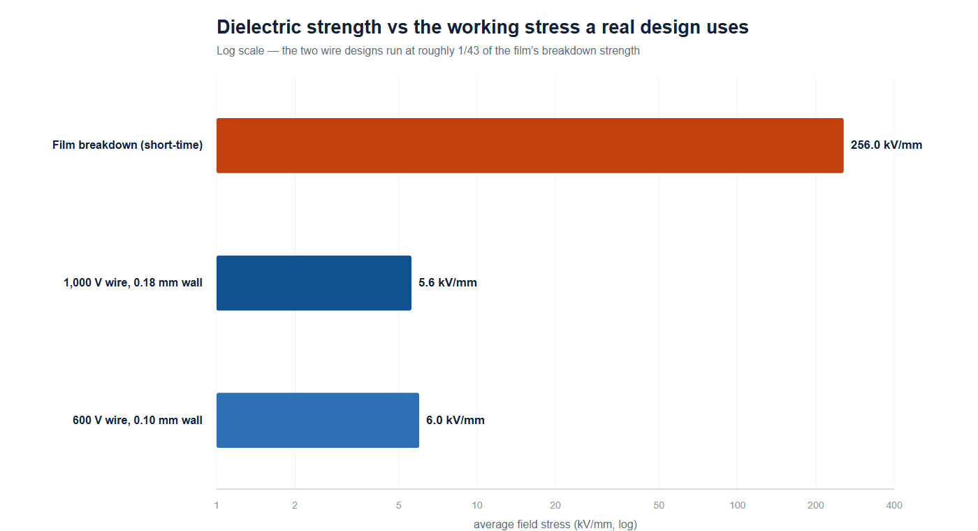
Here is the mistake that most “is Kapton good for high voltage” discussions make. The datasheet for a polyimide film will quote a dielectric strength of roughly 256 kV/mm (polyimide film datasheet) — about 6,500 V/mil on a 25 µm film, measured by ASTM D149 as a short-time breakdown on a flat, dry sample. Read naively, that says a 0.18 mm wall should hold about 46 kV. Real polyimide wires rated 1,000 V have a 0.18 mm wall. The two numbers are off by a factor of forty.
The reason is a single, simple relationship. The average electric stress a wall actually sees is just the working voltage divided by the wall thickness:
E = V / d
where E is the average field stress in kV/mm, V the applied voltage in kV, and d the insulation wall in mm. Nothing about breakdown strength appears in it, and that is the point. A wire is never limited by the flat-sample breakdown strength; it is limited by partial discharge — tiny, repeated sparks that start in the air pockets and layer gaps of the construction, well below the breakdown voltage, and erode the film over time. The voltage at which those discharges start is called the partial-discharge inception voltage, or PDIV, and it is a geometry problem, not a material one.
This is exactly why the material supplier sells a dedicated corona-resistant grade: standard polyimide film degrades under sustained partial discharge, and the corona-resistant formulation extends life under those repeated micro-arcs. The measurement method for partial discharge — apparent charge versus voltage, on the assembled part — is standardized in IEC 60270. If a spec quotes only a breakdown voltage and never mentions PDIV or a partial-discharge measurement, the voltage rating is not yet fully specified.
Why every real design parks at about 6 kV/mm
The cleanest evidence for this is what commercial designs actually do, independent of any datasheet claim. Take two public polyimide equipment-wire datasheets from the same manufacturer family. One is a 1,000 V type with a nominal 0.18 mm wall; the other is a 600 V type with a 0.10 mm wall. Run the same arithmetic on both:
- 1,000 V ÷ 0.18 mm ≈ 5.6 kV/mm
- 600 V ÷ 0.10 mm ≈ 6.0 kV/mm
Two different products, two different voltages, two different wall thicknesses — and the average working stress lands at the same ~6 kV/mm. That is about 1/43 to 1/46 of the film’s 256 kV/mm breakdown strength. If breakdown strength governed the design, a manufacturer would shave the wall to the bone to save money and weight. They do not — they all stop at the same field stress, because that is where partial discharge stays suppressed over the life of the wire.
Practical consequence: do not pick a high-voltage wire by its “dielectric strength.” Pick it by its working stress (E = V / d) and ask for the PDIV and any corona-resistance requirement in writing. A “thin-wall 1,000 V” spec is a contradiction you should catch on the drawing before it becomes a field failure.
Thinner film, lighter wire — and why that matters
The same tape construction that makes polyimide different is also what makes it light. Because the film is thin and strong, a polyimide wall can be thinner than a silicone or PVC wall for the same duty. Thin wall compounds into real grams, and the effect is strongest exactly where wire is thinnest.
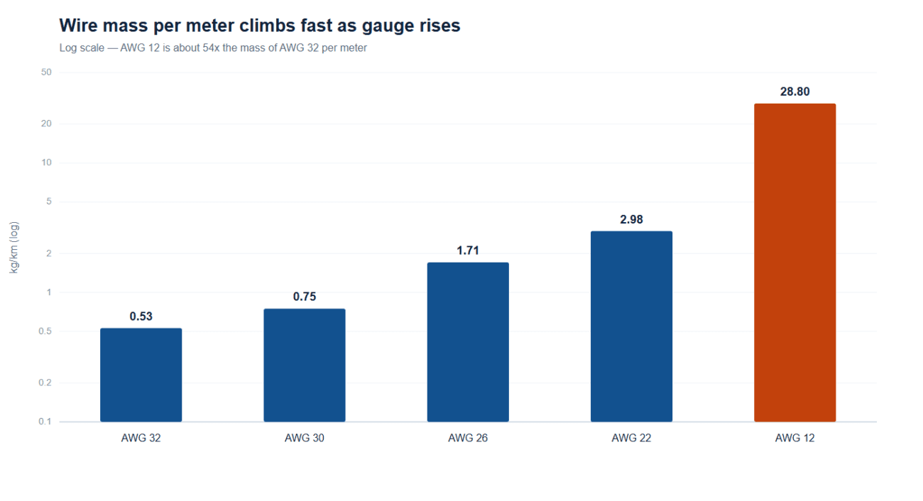
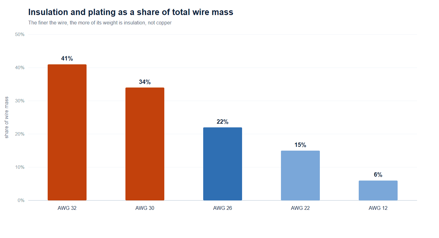
Reversing a published mass table by cross-section and copper density shows insulation (plus any plating) as a share of total wire mass: at AWG 32 roughly 41 percent of the wire’s weight is insulation, at AWG 30 about 34 percent, falling to 22 percent at AWG 26 and just 6 percent at AWG 12. The finer the wire, the more of it is insulation — so for a signal-heavy harness made of many thin conductors, the biggest weight lever is the wall thickness, not the wire gauge. That is the structural argument for polyimide in weight-critical harness work, and it is the exact bridge to our companion article on drone wire harness weight, vibration and EMI.
Choosing between the four
Bringing it together, the decision usually reduces to one honest question: what stress is this wire actually going to see, for how long?
- Motion, high flex, moderate heat → silicone. It stays flexible in the cold and survives constant movement; it is the weak pick for vacuum and radiation.
- 150 °C ceiling, uniform stripping, mid cost → FEP. It extrudes cleanly and terminates without the PTFE sintering step, which is why UL1331 is the workhorse hook-up wire. Our UL1331 FEP wire and the silicone wire harness page sit at this end of the scale.
- 200–260 °C plus chemical and low-outgassing demands → PTFE, accepting the higher cost and the stiffer feel.
- Highest temperature, radiation, vacuum, or a mass budget → polyimide tape, accepting the cost and, at high voltage, the partial-discharge discipline described above.
The same arithmetic governs EV high-voltage harnesses, where wall thickness is set by the working stress you are willing to live at, not by the breakdown figure on a datasheet.
At HKWIRE we do not stock a Kapton insulated cable off the shelf; what we build are harnesses and assemblies to your drawing, including ones that call out polyimide, PTFE, FEP or silicone conductors. The point of this article is to make the material choice correctly on the drawing, before any of the geometry gets locked in. When a customer specifies polyimide, we build and test to the drawing, and our test capability covers continuity, insulation resistance and dielectric withstand — the last of which is exactly where a partial-discharge or corona requirement needs to be written down, not assumed.
Is Kapton a wire insulation or a tape?
Both. Kapton is a polyimide film; on a wire it is applied as wound tape that becomes the insulation wall. There is no “Kapton extrusion,” because polyimide does not melt — which is why polyimide wire construction and voltage class are so tightly linked.
What is the difference between Kapton and PTFE wire?
PTFE is a fluoropolymer that is paste-extruded and sintered; Kapton is a polyimide film that is wrapped. PTFE is the workhorse for 200–260 °C chemical and low-outgassing duty; polyimide goes higher on temperature and adds radiation and vacuum tolerance, at a higher cost and with a different high-voltage discipline.
Can a Kapton insulated cable handle high voltage?
Yes, but “high voltage” is set by partial-discharge inception, not by the film’s breakdown strength. A real polyimide wire rated 1,000 V uses about a 0.18 mm wall — roughly 6 kV/mm average stress — and relies on controlled layers and overlap. Specify the voltage, the wall and the PDIV together, and say whether a corona-resistant grade is required.
Should I choose Kapton or silicone for my harness?
Choose silicone for motion and flex at moderate heat, and polyimide for the highest temperature, radiation, vacuum or a hard mass budget. They are not substitutes; a run that constantly bends and only sees 180 °C is better served by silicone, and a fixed high-temperature or vacuum run is where polyimide earns its cost.
Frequently asked questions
What continuous temperature should I specify for a Kapton insulated cable?
It depends on the grade and the plating. Polyimide constructions are usually quoted at 200–300 °C continuous, against 200–260 °C for PTFE, 150 °C for FEP and −60 to +180 °C for standard silicone, or about +200 °C for a high-temperature grade. Treat those as starting points: the figure for your part comes from the datasheet for the exact construction.
Which temperature figure belongs on the drawing?
Name all three rather than one: the continuous operating temperature, the short-term peak the assembly has to survive, such as a solder or reflow excursion, and the UL 746B thermal index. Polyimide makes the point clearly — a film with roughly 240 °C electrical RTI carries only about 200 °C mechanical RTI, so it keeps insulating long after it has lost tensile strength. In a harness that flexes, the mechanical number governs how long it lasts.
Does vacuum or radiation exposure change the insulation choice?
It often decides it. Polyimide and PTFE or FEP are rated excellent for low outgassing and radiation tolerance, while silicone is poor on outgassing and only fair on radiation. Where a cable runs in vacuum or sees ionizing radiation — space hardware, vacuum chambers, beamline and some analytical instruments — the insulation follows those two columns rather than the temperature one.
How much weight does thin-wall polyimide actually save?
On fine signal conductors it is the largest single lever, because insulation is already a third to two-fifths of a 30–32 AWG wire’s own mass. On a heavy power lead the saving is marginal: insulation is only about 6 percent of a 12 AWG wire. Reducing the connector count and the number of branches usually moves more grams than swapping insulation, so do that first.
What is the minimum order quantity for a high-temperature harness?
Production runs start at 500 pcs per part number and ship 14 working days after first article approval; prototypes and engineering samples are built from 1 to 50 pcs and ship in 3 working days. Send the insulation wall, the working voltage and the duty cycle, and we will quote a tested assembly rather than a catalog part.
Specifying a high-temperature or high-voltage harness?
HKWIRE builds cable assemblies to your drawing across silicone, FEP, PTFE and polyimide conductors — with continuity, insulation-resistance and dielectric-withstand testing, and the partial-discharge checks your application needs written into the plan rather than assumed. Send the drawing and the duty cycle, and we will quote a tested assembly.