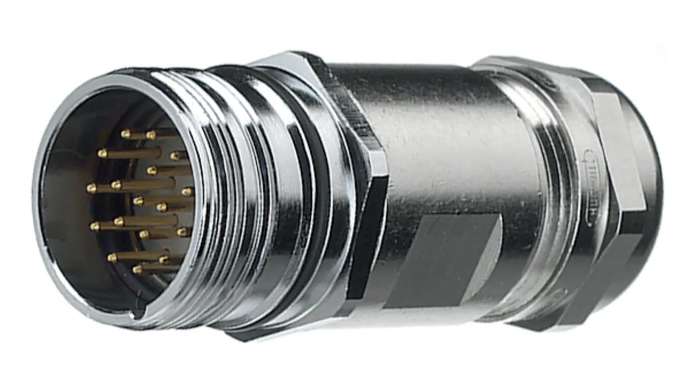
M23 Screw Lock Cable for Servo Motor Power and Encoder Feedback
An M23 screw lock cable puts servo power and encoder feedback into one coupling: motor phases and brake on the large contacts, feedback and thermal sensor on a separately shielded group. Built to the motor and drive model you give us.
Overview
An M23 screw lock cable carries the two things a servo axis cannot work without, and it carries them in opposite electrical conditions. The motor phases are switched at several kilohertz by the drive and carry sharp edges; the feedback signal sitting two millimeters away is an analog sine/cosine track, a resolver excitation, or a serial absolute-position link that has to survive right next to them. The M23 shell exists to put both in one coupling – one screw lock, one cable clamp, one slot in the cable track – and the whole art of the build is keeping the two groups from talking to each other. We build these to the motor and drive model you supply.
Two jobs in one coupling
Running power and feedback down two separate cables means two connectors on the motor, two clamps, two strain reliefs and two paths through a moving cable track. It also means two chances to get the shielding wrong. A hybrid assembly halves the hardware at the motor end and, done properly, improves the electrical result, because the shield separation is designed in at the same time as the pinout rather than improvised on site.
| Conductor group | Contacts | Shielding | Why it is treated that way |
|---|---|---|---|
| Motor phases and earth | Large power contacts, typically four | Under the overall braid only | Switched at the drive switching frequency; the noise source |
| Brake pair | Two, usually mid-size | Under the overall braid | Inductive DC; needs separating from the feedback group |
| Encoder feedback | Four to a dozen signal contacts | Own foil or braid, plus the overall braid | The victim: low-level analog or serial that must not pick up switching edges |
| Temperature sensor | Two, thermistor or switch | With the feedback group or separately, per build | High impedance and slow, so it is easily disturbed |
Why the feedback group gets its own shield
Putting both groups in one jacket without separation is how you end up chasing intermittent position faults that only appear under load, only at one speed, and never on the test bench. The feedback conductors are therefore wrapped in their own foil or braid before the whole bundle goes under an overall braid, and that overall braid is clamped to the metal shell at both ends so it actually terminates rather than dangling. Two details decide whether it works: the individual shield has to be continuous through the connector, and the drain has to be terminated the way your drive expects – some want it at both ends, others at the drive end only. Tell us which and we build to it.
Reading the pinout
There is no single M23 servo pinout, and this is the part that decides whether the cable works. Power positions broadly follow the conventions described in IEC 61915 and the hybrid layouts associated with DESINA-style installations, but which contact carries which phase, where the brake pair sits, and what the feedback positions are wired for vary between drive makers and even between motor frames from the same maker. Resolver, sin/cos incremental, absolute serial and commutation-track variants all land on different pins.
| Zone | What lands there | What varies |
|---|---|---|
| Outer power ring | Three motor phases plus protective earth | Phase order and whether the shell or a contact carries earth |
| Brake positions | Holding brake pair | Fitted or not; polarity; whether it shares with a thermal switch |
| Feedback group | Encoder orResolver excitation and signals, serial clock and data | Feedback type, voltage, and whether a battery or sense pair is included |
| Thermal pair | Motor temperature sensor | Thermistor, PTC or a simple switch |
| Keying | Mechanical coding of the insert | Differs between makers – order the two halves as a matched set |
Because so much of this is vendor-specific, the fastest route to a correct sample is the motor model and the drive model, or the old cable. A written description of a 12-pin connector is not enough.
Jacket and flex life for moving axes
Where the axis moves, the jacket has to be a drag-chain grade PUR over fine-stranded conductors, with the lay chosen for flexing rather than for static installation. Shield coverage should be high and the braid angle set so it does not open up under repeated bending – a braid that spreads at the bend is a shield that stops working halfway through the cable’s life. On a fixed machine base a PVC jacket is perfectly adequate and costs less. Length is usually driven by the cable track path rather than by straight-line distance, so measure the track rather than guessing.
Key specifications
| Connector family | M23 circular, screw coupling |
|---|---|
| Function | Servo motor power plus encoder feedback in one connector |
| Feedback shielding | Separate shield over the feedback group, plus overall braid |
| Conductor groups | Motor phases and earth, brake pair, feedback, temperature sensor |
| Jacket options | Drag-chain PUR for moving axes, PVC for fixed runs |
| Connector variants | Power and signal shell sizes, straight or right angle |
| Pinout | Built to the motor and drive model supplied by the buyer |
| Length | Made to order |
Typical applications for this M23 screw lock cable
- Servo axes on machine tools, packaging machines and pick-and-place units
- Robot arms and gantries with one-cable servo connections
- Spindle drives with integrated feedback
- Printing, converting and web-handling lines with many synchronized axes
- Retrofit of older drives where the original hybrid cable is no longer available
What we need from you
- The motor model and the drive model, or the existing cable.
- The feedback type: resolver, sin/cos 1 Vpp, absolute serial, or commutation only.
- Whether the brake pair is needed, and whether the thermal sensor is a thermistor, a PTC or a switch.
- The connector size and coding your motor uses, since M23 shells come in power and signal variants.
- Whether the axis moves, and the measured length of the cable track.
- Where the drain is terminated – at the drive end only, or both ends.
- Quantity, and whether this is a prototype or a production order.
Workmanship and testing
Workmanship on M23 Screw Lock builds follows IPC/WHMA-A-620 Class 3, the line is run under ISO 9001, and the termination range is 32 to 12 AWG. No M23 assembly is boxed before 100% continuity and pinout are confirmed, and seal checking is quoted whenever an ingress rating is on the drawing.
Material declarations against RoHS and REACH are issued per project, alongside the dimensional and electrical reports agreed at quotation; see certifications, compliance and material declarations. Where your drawing names a UL style or another approval, the build follows your drawing and ships with the supporting document rather than a claim of our own. The strain relief and molded body are produced on tooling we cut ourselves see in-house mold making and overmold tooling so the tool is quoted separately, owned by you, and available for repeat runs years later. More background: how we handle build-to-print orders.
Custom builds and ordering
Quote M23 Screw Lock builds from 1 to 50 pcs and they ship in 3 working days; at volume the minimum is 500 pcs with 14 working days after approval. Tooling not already held adds around 10 working days. OEM and ODM M23 runs go out under your part number and labeling and material certificates and first-article reports are available on request.
Related servo and feedback assemblies
- Custom Servo Motor Cable Assembly
- Hybrid Servo Cable for one-cable solution servo drives
- Encoder Feedback Cable with PUR jacket for digital servo loops
- OEM Servo Encoder Cable cross-reference pages by machine family
- KUKA Robot Encoder Cable compatible with 00-174-775
- Hybrid Robot Torsion Cable with CAT6 data pair, power and control cores
The feedback device itself is described in the rotary encoder reference. Full ranges: Screw-Lock Molded Cable • Signal and Data Cables • Custom Wire Harnesses.
Frequently Asked Questions
Can you supply a standard M23 servo pinout?
No. Power positions broadly follow the IEC 61915 and DESINA-style conventions, but the phase order, brake position and feedback assignment vary by maker and by motor frame. Give us the motor and drive model.
Can I run power and feedback in two separate cables instead?
You can, and some machines do. The hybrid build saves a connector, a clamp and a track slot at the motor, and lets the shield separation be designed in rather than improvised.
Where should the feedback drain be terminated?
Whichever way your drive manual specifies – it differs. Tell us and we build to it; the wrong choice turns the cable into an antenna.
Do I need the drag-chain jacket?
If the axis moves, yes. A PVC jacket on a moving cable track will not last, and the braid on a non-flexing construction opens up at the bend.
What is the minimum order?
Quote M23 Screw Lock builds from 1 to 50 pcs and they ship in 3 working days; at volume the minimum is 500 pcs with 14 working days after approval.
| Category | Screw-Lock Molded Cable |
|---|---|
| Connector family | M23 circular, screw coupling |
| Function | Servo motor power plus encoder feedback in one connector |
| Feedback shielding | Separate shield over the feedback group, plus overall braid |
| Conductor groups | Motor phases and earth, brake pair, feedback, temperature sensor |
| Jacket options | Drag-chain PUR for moving axes, PVC for fixed runs |
| Connector variants | Power and signal shell sizes, straight or right angle |
| Pinout | Built to the motor and drive model supplied by the buyer |
| Length | Made to order |