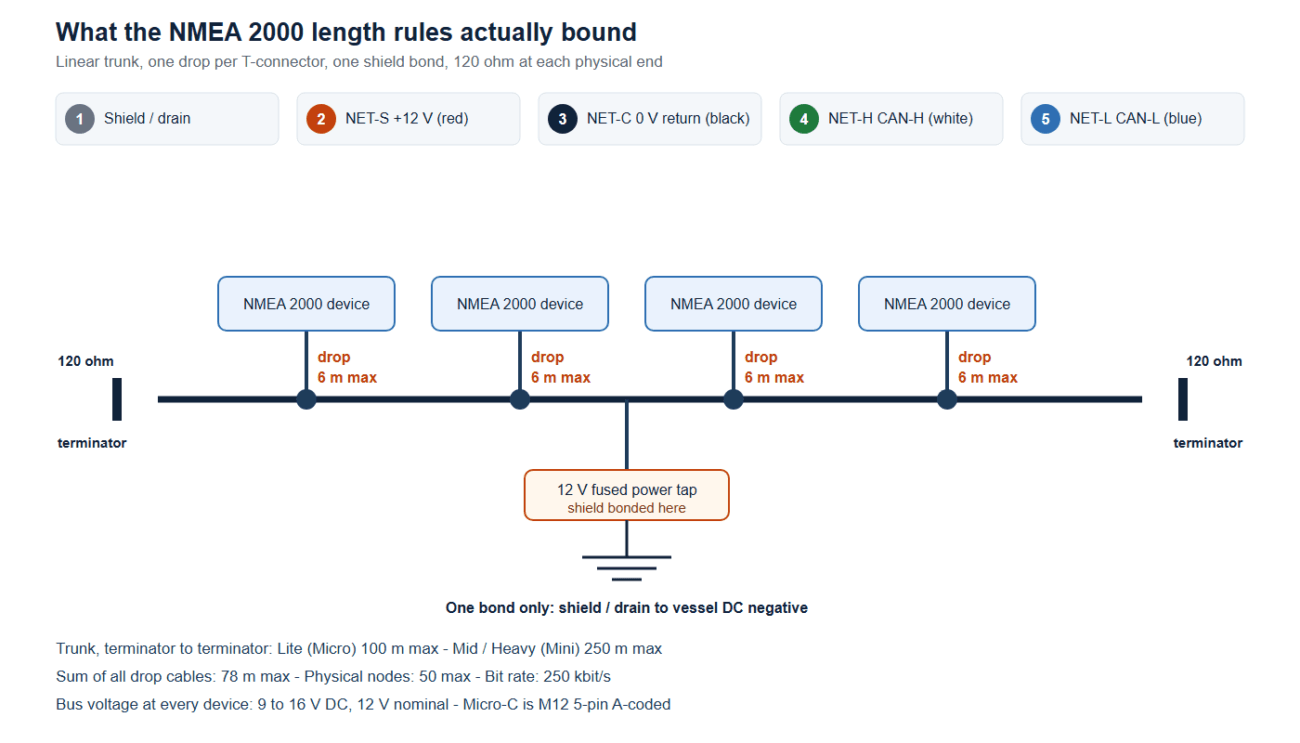
An NMEA 2000 drop cable is the short cordset that hangs a device off the trunk: half a meter inside a helm console, six meters up a mast, rarely anything in between. Most buying guides stop at two numbers you have already read somewhere. Keep the drop under 6 m. Keep network voltage drop under 1.5 V. Both are real and both appear in manufacturer documentation. Neither is what ends a busy network first. On a 30 m trunk carrying 40 LEN of electronics, the limit you cross first is the ground offset built up on the return conductor, because that offset is subtracted directly from the common-mode range of every CAN transceiver on the bus.
This guide works from the physical layer upward: connector and pin definition, the network limits every drop lives inside, the return-path calculation that sizes a trunk, the timing behind the 6 m rule, and what to do with the shield on a boat that lives in salt spray.
NMEA 2000 Drop Cable Basics: Two Pairs, Five Pins, One Current Budget
NMEA 2000 is standardized internationally as IEC 61162-3, the serial data instrument network for maritime navigation and radiocommunication equipment. The physical layer is CAN: differential signaling at 250 kbit/s, which is a bit time of 4 µs. That bit time matters later, when we look at what a long drop does to the edges of a bit.
The connector is a 5-pin M12 with screw locking, A-coded — the interface family standardized as IEC 61076-2-101. In NMEA 2000 language this is the Micro-C connector. The larger variant is the Mini connector, a 7/8″-16UN shell used with heavier cable grades. Both are 5-way and carry the same five signals.
| Pin | Signal | Wire color | What it does |
|---|---|---|---|
| 1 | Shield / drain | Bare | Overall shield and drain wire, bonded to the vessel ground reference at one point only |
| 2 | NET-S | Red | Network power positive, 12 V nominal |
| 3 | NET-C | Black | Network power return and 0 V reference — the conductor this article is about |
| 4 | NET-H | White | CAN-H, high side of the differential data pair |
| 5 | NET-L | Blue | CAN-L, low side of the differential data pair |
A NMEA 2000 drop cable therefore contains two twisted pairs plus a drain: power on pins 2 and 3, data on pins 4 and 5, all inside one shield that lands on pin 1. Both pairs matter to the same calculation — the part that gets lost when an NMEA 2000 drop cable is treated as a passive jumper. The data pair carries the differential signal, and the power pair carries the current that every device draws through its transceiver, whether or not that device has its own separate supply.
Device current is quoted as a Load Equivalency Number. One LEN is 50 mA at 12 V, as stated in Garmin’s NMEA 2000 technical reference and in Actisense’s network design guide, so a device rated at 4 LEN takes roughly 200 mA off the bus. Add the LEN figures of every device, multiply by 50 mA, and you have the current that travels out along NET-S and back along NET-C — the input to the calculation below.
Network Limits Every NMEA 2000 Drop Cable Must Respect
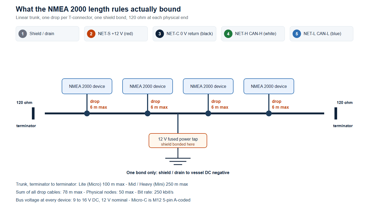
NMEA 2000 is a linear bus, not a star and not a daisy chain of devices. Every device connects through a T-connector, or a bulkhead feedthrough that behaves like one, and both physical ends of the trunk carry a 120 Ω terminator. Measured across CAN-H and CAN-L on an unpowered network, the two terminators in parallel read approximately 60 Ω — the fastest field check you can make before powering anything up.
| Parameter | Limit | Where it comes from |
|---|---|---|
| Trunk (backbone), Lite / Micro cable | 100 m, terminator to terminator | Actisense, Garmin |
| Trunk, Mid or Heavy cable | 250 m, terminator to terminator | Actisense |
| Any single drop cable | 6 m maximum | Actisense, Garmin |
| Sum of all drop cables on the network | 78 m maximum | Actisense |
| Physical nodes | 50 maximum | Actisense |
| Source addresses | 252 (0–251); one device may claim several | Actisense |
| Termination | 120 Ω at each end; about 60 Ω measured across the pair | Actisense, Garmin |
| Bus voltage at every device | 9–16 V DC, 12 V nominal | Actisense, Garmin |
| Bit rate | 250 kbit/s, bit time 4 µs | IEC 61162-3 / CAN |
| Network supply current, Lite cable | 3 A, equivalent to 60 LEN | Actisense |
The 6 m limit for a NMEA 2000 drop cable and the 78 m cumulative figure most often decide whether an installation is buildable. Aft cabin, flybridge, and masthead devices add up fast: eight drops of 6 m consume 48 m of the 78 m budget, and that budget does not improve with a heavier cable grade.
The rule quoted alongside these is a voltage drop limit of 1.5 V end to end, as stated in Digital Yacht’s NMEA 2000 networking guide. It keeps supply voltage at the furthest device above the 9 V floor, and it is generally satisfied long before the network develops a data problem.
The Ground Offset Nobody Calculates
Every milliamp that leaves the power tap along NET-S has to come back along NET-C. NET-C is copper, so it has resistance, and current through it produces a voltage difference between the two ends of the return path. Two devices on the same network therefore do not share a ground: the far device’s ground sits hundreds of millivolts — or several volts — away from the ground near the power tap.
CAN transceivers tolerate a bounded amount of that. ISO 11898-2 defines a common-mode bus voltage window of −2 V to +7 V, quoted directly in Texas Instruments’ CAN physical layer application note, which also describes the window as tolerable ground offset. The low side is the one that matters here, because NET-C offset moves the whole bus negative with respect to the distant node’s local ground. Push past −2 V and the transceiver can no longer resolve recessive from dominant.
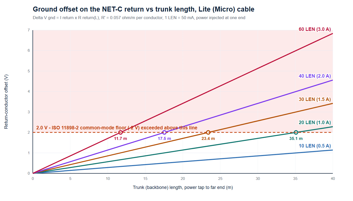
The whole calculation reduces to one relation, read two ways. Read for voltage, it gives the offset a given load produces over a given length. Read for length, it gives how much trunk that load can occupy before the −2 V floor is reached.
ΔV_gnd = I_return × R_return(L) — and the same relation read for length: L_max = ΔV_allow / (I_return × R′)
Here I_return is the network current returning to the power tap in amperes, R_return(L) is the return conductor’s resistance over the trunk length L in meters, and R′ is its resistance in ohms per meter. For Lite (Micro) cable Actisense publishes 0.057 Ω/m per conductor, with Mid at 0.015 Ω/m and Heavy at 0.012 Ω/m. This is one relation, not two: the second line is the first solved for the length you are allowed to build.
The table below covers a trunk fed from one end, where the full network current returns along the whole length. It is the worst case an installer can build, and it is the case most single-tap networks are actually in.
| LEN budget | Bus current | Offset at 10 m trunk | Offset at 20 m | Offset at 30 m | Offset at 40 m |
|---|---|---|---|---|---|
| 10 LEN | 0.50 A | 0.29 V | 0.57 V | 0.86 V | 1.14 V |
| 20 LEN | 1.00 A | 0.57 V | 1.14 V | 1.71 V | 2.28 V |
| 30 LEN | 1.50 A | 0.86 V | 1.71 V | 2.57 V | 3.42 V |
| 40 LEN | 2.00 A | 1.14 V | 2.28 V | 3.42 V | 4.56 V |
| 60 LEN | 3.00 A | 1.71 V | 3.42 V | 5.13 V | 6.84 V |
Read the middle of that table and the practical problem appears. A mid-sized yacht trunk of 30 m carrying 40 LEN — two multifunction displays, a radar interface, an autopilot, a sounder module, an engine gateway, an AIS transceiver — runs at 3.42 V of return-path offset. That is 1.7 times the transceiver’s entire negative common-mode allowance, produced by a network whose supply voltage is still comfortably inside 9–16 V at every device.
Back-Calculating Allowed Trunk Length From a LEN Budget
Installers rarely choose the trunk length; the boat chooses it. What you can choose is the cable grade, the number of devices on the segment, and where the power tap goes. This is where a NMEA 2000 drop cable stops being a commodity part and becomes a sizing decision. The length reading of the relation above turns those choices into a number you can check against the boat.
Two allowances are worth tabulating. The first is 2.0 V, the full ISO 11898-2 negative common-mode allowance, which is the absolute ceiling and leaves nothing for temperature drift, connector resistance, or a second supply point. The second is 1.0 V, a deliberate half-margin many installers work to. Neither is published by NMEA as a trunk rule; both follow from the transceiver window.
| LEN budget | Bus current | Lite, 2.0 V allowance | Lite, 1.0 V allowance | Mid, 2.0 V allowance | Mid, 1.0 V allowance |
|---|---|---|---|---|---|
| 10 LEN | 0.50 A | 70 m | 35 m | 266 m | 133 m |
| 20 LEN | 1.00 A | 35 m | 17 m | 133 m | 66 m |
| 30 LEN | 1.50 A | 23 m | 12 m | 88 m | 44 m |
| 40 LEN | 2.00 A | 17 m | 9 m | 66 m | 33 m |
| 60 LEN | 3.00 A | 11 m | 6 m | 44 m | 22 m |
The table explains why cable grade is a first-order decision, not a price decision. Lite cable is limited to 100 m of trunk by the manufacturers, and the return path becomes the binding constraint at 23 m with 30 LEN on board. Moving that load to Mid cable — 16 AWG power conductors at 0.015 Ω/m — pushes the constraint out to 88 m, past anything a sub-40 m yacht trunk will need. If your trunk exceeds roughly 20 m and carries more than a handful of devices, the return path has already made the choice for you.
The power tap position is the free second lever. A tap at one end forces the entire return current through the entire length of NET-C; move the tap to the middle and the current splits into two return paths, each half as long. On a 40 m trunk at 20 LEN, an end feed produces 2.28 V of worst-node offset and a mid-trunk feed produces 0.57 V — a factor of four for the cost of moving one connector.
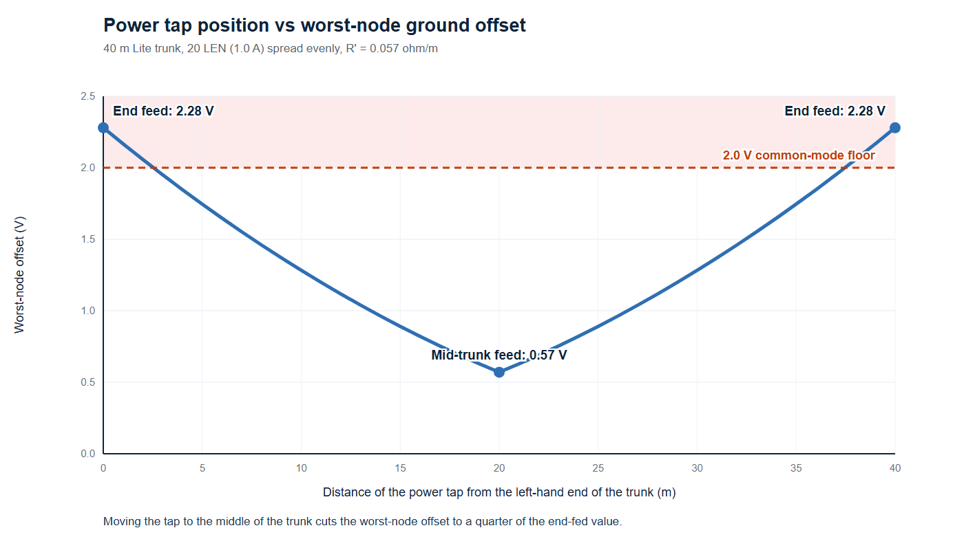
Mid-trunk injection is the most effective change for an installer who cannot shorten the trunk or shed devices, and it is usually cheaper than a second run of heavier cable. Products built for exactly this interface — Micro-C drop cables on one side of the bulkhead and sealed bulkhead connectors on the other — turn the tap position into a documented part of the build rather than something decided by where the wire happened to reach.
What the 6 m NMEA 2000 Drop Cable Rule Really Protects
The 6 m limit is not a voltage rule; it is a timing rule expressed as a length, and the arithmetic makes that clear. Signal propagation in a twisted pair runs at about 5 ns per meter, the value Texas Instruments uses in the same application note, which puts 10 ns per meter on the round trip. At 250 kbit/s one bit occupies 4 µs.
| Drop length | One-way propagation | Round trip | Share of one 4 µs bit |
|---|---|---|---|
| 0.5 m | 2.5 ns | 5 ns | 0.12 % |
| 1 m | 5 ns | 10 ns | 0.25 % |
| 2 m | 10 ns | 20 ns | 0.50 % |
| 3 m | 15 ns | 30 ns | 0.75 % |
| 6 m | 30 ns | 60 ns | 1.50 % |
The reflection problem is what makes 6 m the number rather than 12 m or 30 m. A stub is not terminated: it ends at a device connector, and the signal running down it reflects back. The rule of thumb is that an unterminated stub stays electrically invisible while it is a small fraction of the distance a signal travels in one edge transition. Applied to a slew-rate-limited driver — the 160 ns transition used in the TI example — the ceiling lands at roughly five to six meters. That is the NMEA 2000 6 m limit, and it does not scale up if you buy better cable.
One distinction trips up installers in both directions. The 6 m rule constrains the length of the unterminated stub between a T-connector and a device. It does not constrain which reel the cable came off. A pre-made cordset sold as a NMEA 2000 drop cable can serve as a short run of trunk between two T-connectors, because once it sits between T-connectors it is terminated at both ends and carries the trunk rather than a stub. What is not allowed is stringing devices along one long cable with no T-connectors, or daisy-chaining drops so that the last device sits 15 m from the trunk. Those arrangements produce the unbounded stub the rule exists to prevent, and they break the 78 m budget without the installer noticing.
NMEA 2000 Drop Cable Grade, Conductor Size, and Jacket Choice
Three cable grades cover NMEA 2000, and the difference between them is almost entirely conductor cross-section. The Actisense Micro cable limitations table and the NMEA committee’s own white paper on NMEA 2000 explained agree on the shape of the table, with small differences worth knowing before you order a reel.
| Grade | Power pair | Data pair | Conductor resistance | Current capacity | Max trunk |
|---|---|---|---|---|---|
| Lite, Micro connector | 22 AWG | 24 AWG | 0.057 Ω/m | 3 A (60 LEN) | 100 m |
| Mid, Micro or Mini connector | 16 AWG | 20 AWG | 0.015 Ω/m | 4 A with Micro, 8 A with Mini | 250 m |
| Heavy, Mini connector | 15 AWG | 18 AWG | 0.012 Ω/m | 8 A | 250 m |
Sources: Actisense cable tables; NMEA 2000 white paper for conductor grades. The Heavy power conductor is published as both 15 and 16 AWG depending on source — confirm against the reel data sheet.
Two details decide how a cable survives on board outside the length question. The first is characteristic impedance: NMEA 2000 cable is a 120 Ω transmission line, and an off-spec cable changes the termination network rather than merely attenuating the signal. The second is current capacity relative to the connector molded onto it. Mid cable with a Micro connector is a 4 A section; the same cable with a Mini connector is 8 A. The conductor is capable, the connector is the limit, and a network that is fine on the bench becomes a warm connector in a locker after a season. The trade-off between shielded and unshielded constructions is covered in shielded versus unshielded cable, and the fieldbus version of the argument is in industrial fieldbus cable selection.
Jacket material is the third decision when you specify an NMEA 2000 drop cable, and on deck the answer is rarely PVC. A halogen-free low-smoke jacket is the common marine choice for runs inside a vessel, and PUR is the better answer where the cordset is handled, coiled, or flexed. Where the assembly is repeatedly connected and disconnected in weather, the reasoning in waterproof cable assemblies for outdoor use applies directly.
Shield, Drain Wire, Salt Fog, and Where the Bond Goes
Pin 1 connects the overall shield and drain to the network, and what you do with that bond decides whether the shield reduces noise or injects it. Actisense states that the shield must be connected to the vessel’s DC negative bus at one point only, typically at the power tap, and that bonding it at multiple points creates a ground loop that puts noise onto the signal conductors. Texas Instruments gives the same advice for CAN: ground the network at a single point at the source, using a short pigtail through a dedicated pin rather than a long drain lead.
| Practice | Effect on the signal | Cost | When to use it |
|---|---|---|---|
| Bonded at the power tap only | No ground loop; reference shared with the supply | Floating shield section couples capacitively | Default on a vessel with a DC negative bonding system |
| Bonded at both ends | Best high-frequency shield performance on paper | Closes a loop through hull and engine; shield current becomes common-mode noise | Screened cables inside one bonded enclosure |
| Left floating | No loop current | No shield effect where it matters; drain acts as an antenna | Never on a NMEA 2000 run |
| Drain on a short pigtail | Keeps bond impedance low at high frequency | Needs a connector that brings pin 1 out | Any field-terminated run |
A shield bonded at both ends is a better far-field shield and a worse partner for a boat. It closes a loop through the hull, engine block, and bonding system, and any potential difference between those points drives current along the shield. In a marina with poor shore power that current is often at the supply frequency, and it appears as common-mode noise on the pair. Single-point bonding removes the loop; the compromise is floating copper that couples capacitively, which is why the drain lands on a short pigtail at the connector rather than a long wire to a distant bus bar.
Mechanical protection does the rest. Micro-C connectors as a family are sealed to IP67 or better, which covers immersion and washdown as defined in IEC 60529; the difference between the immersion classes is set out in our IP67 vs IP68 vs IP69K comparison. Above deck the relevant weathering standard is salt mist testing to IEC 60068-2-11, which a molded or sealed assembly should have been qualified against if it is going on a mast or a deck edge. Stainless coupling hardware and gold-plated contacts matter more here than in a dry console: gold resists the fretting and film growth that turns a marginal contact into a surprise after a few seasons, a mechanism covered in gold versus tin contact plating.
For through-deck transitions, the connector matters as much as the cable. A sealed NMEA 2000 bulkhead connector keeps the shield bond and the gland inside one fitting, so the drain does not have to be re-made inside a wet locker. Where the same route carries more than one network, a pigtail bulkhead panel connector or an IP68 deck feedthrough keeps the enclosure rating intact, following the same logic as panel mount connector selection.
Not every 5-pin M12 cordset is a NMEA 2000 drop cable, so check before ordering. An M12 CAN bus cable carries the same differential pair on pins 4 and 5 but may not combine pin 2 power, pin 1 shield, and 120 Ω characteristic impedance in one construction. A device that expects to be bus-powered needs all three. If the run ends in a washdown area, stainless-shell and sealed constructions such as an M12 IP69K washdown cable or an IP67 molded M12 cordset keep the same pinout with better sealing. The electrical core — LEN, current, return resistance, common-mode margin — is unchanged by the jacket, which is why the calculation has to come before the part number.
FAQ
How long can a NMEA 2000 drop cable be?
6 m for every NMEA 2000 drop cable grade, per Actisense and Garmin. The limit is a timing constraint on the unterminated stub between the T-connector and the device, not a voltage constraint, and it does not increase if you buy heavier cable.
What is the difference between a NMEA 2000 drop cable and a backbone cable?
They share the same five conductors, pinout, and construction; the difference is where the cable sits. An NMEA 2000 drop cable runs from a T-connector to a device and is limited to 6 m. A backbone segment runs between two T-connectors and is terminated by the trunk at both ends.
Is 1 LEN really 50 mA?
Yes. One LEN equals 50 mA at 12 V, stated in Garmin’s NMEA 2000 technical reference and in Actisense’s design guide. Round LEN up, never down, and include devices that have their own supply: their transceiver still draws from the bus.
My voltage drop is only 0.9 V. Why does my network still have errors?
Because supply drop and return-path offset are two different measurements. The 1.5 V rule describes supply voltage difference from one end of the network to the other. The offset that attacks the data pair develops on NET-C alone, referenced between two nodes’ grounds. A 30 m Lite trunk carrying 40 LEN develops 3.42 V of it while still showing acceptable supply drop.
Can I use a longer NMEA 2000 drop cable if the network still works?
It may work, and it will not be reliable in the way the standard intends. Past 6 m the stub is no longer electrically short compared with the signal edge, so reflections arrive while receivers are sampling and bit margin narrows. The failure mode is intermittent: dropped frames under noise, CRC errors, and bus-off events on a network that tests clean on a bench.
Should the shield be grounded at both ends to reduce noise?
Not on a NMEA 2000 vessel network. Bonding at both ends closes a loop through the hull and bonding system, and any potential difference drives current along the shield. Use a single bond at the power tap, with the drain on a short pigtail.
Does moving the power tap really change anything on a short network?
It changes the worst-node offset by up to a factor of four: on a 40 m trunk at 20 LEN, an end feed produces 2.28 V and a mid-trunk feed 0.57 V. Supply drop improves at the same time, and the change costs nothing but planning.
What should I put on the drawing for a NMEA 2000 drop cable?
Pin-to-pin continuity for all five ways, conductor gauge for both pairs, characteristic impedance, the shield bond point and whether the far end is left open, the drop length against the 6 m limit, the cumulative drop total, and the LEN the device contributes. Add the salt mist and IP qualification the location requires, and state the interface as Micro-C M12 5-pin A-coded or Mini 7/8″-16UN.
Need NMEA 2000 drop cable assemblies built to your network drawing?
HKWIRE builds Micro-C M12 5-pin drops, bulkhead connectors, and custom lengths to drawing, with the shield bond, conductor gauge, and sealing specified for the location. Send us the trunk layout and the LEN total, and we will quote the assembly that fits your network.
Most NMEA 2000 cable problems are not cable problems. They are network geometry problems that a cordset then has to live with: a trunk that is long relative to its load, a power tap at the wrong end, three drops where one was drawn, a drain bonded twice. Specify the NMEA 2000 drop cable after those decisions are made, not instead of making them, and the selection gets simple — five pins, the right gauge, sealed for the location, and short enough that the stub stays invisible to the bit that has to travel down it. That is the part HKWIRE builds to your drawing rather than to a catalog length.