M12 12 Pin Cable, High Density Cordset for Encoders and Valve Blocks
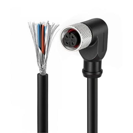
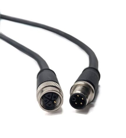
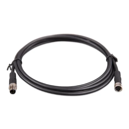
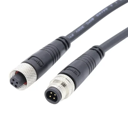
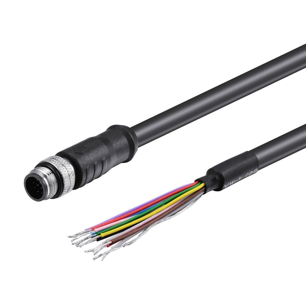
An M12 12 pin cable that collapses four separate sensor runs into one connector on the same 12 mm thread. Shielded multi-core with signal and supply cores sized separately, braided screen with drain, straight or right-angle, built to your pinout.
Last updated: 13 September 2026
Overview
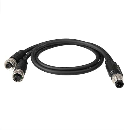
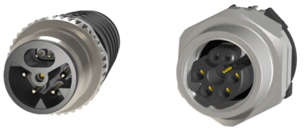
An M12 12 pin cable is what you reach for when one device needs more conductors than a standard sensor cordset can carry. A proximity switch needs three; a multi-turn absolute encoder, a resolver or a valve block with eight solenoids needs far more. Running four separate 4-pin cables to one device costs space, weight and four sealing points. Twelve positions collapse that into one connector on the same 12 mm thread, and it is the practical sweet spot before assembly yield starts to fall away.
Key Specifications
| Coding | A-code, high density |
|---|---|
| Positions | 12 – other counts from 2 to 17 on request |
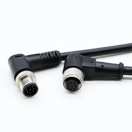
| Connector A | M12 A-coded 12-pin, straight or right-angle |
| Connector B | M12 A-coded 12-pin, or open leads |
| Conductors | Shielded multi-core, mixed signal and supply sizes |
| Jacket | PUR or PVC |
| Shielding | Braided overall screen with drain wire |
| Ingress rating | IP67 when mated – confirm per build |
Pin count versus what it costs you
A-code runs from two positions up to seventeen, but density is not free. Every extra contact is another crimp that has to be right, and the tooling and inspection burden rises faster than the conductor count does. Twelve is where most of our customers land.
| Positions | Typical device | Assembly note |
|---|---|---|
| 4 | Simple sensors and actuators, IO-Link devices | Highest yield, lowest cost, shortest lead time |
| 8 | Two-channel sensors, compact cameras, small I/O blocks | Common middle ground |
| 12 | Encoders, valve manifolds, multi-channel I/O | Best density-to-yield trade-off in the range |
| 17 | Maximum A-code density | Demanding crimp tooling and inspection; quote only |
12-position color code reference
The sequence below is the color code most sensor and encoder makers follow for a 12-position A-coded shell. It is a convention, not a guarantee – we terminate to the pinout you send, and where your device uses a different sequence we will mark the cores to match.
| Pin | Color | Pin | Color |
|---|---|---|---|
| 1 | Brown | 7 | Black |
| 2 | Blue | 8 | Gray |
| 3 | White | 9 | Red |
| 4 | Green | 10 | Violet |
| 5 | Pink | 11 | Gray / pink |
| 6 | Yellow | 12 | Red / blue |
Where a 12-pin build sits in the M12 coding family
High density and coding are separate decisions: twelve positions is an A-code arrangement, the same keyway as an ordinary 4-pin sensor lead. Everything else in the family is keyed for a different job. The map below covers all of them.
| Code | Positions | Carries | Typical use |
|---|---|---|---|
| A | 3 / 4 / 5 / 8 / 12 | DC sensor supply and signals, IO-Link | Proximity switches, photoelectric sensors, valve plugs |
| B | 5 | PROFIBUS-DP fieldbus | Legacy drives, remote I/O racks, weigh scales |
| C | 3 to 6 | AC power, dual keyway, extended earth | AC sensors, solenoid coils, legacy actuator blocks |
| D | 4 | 100 Mbit/s Ethernet over two pairs | PROFINET, EtherNet/IP, EtherCAT device drops |
| K | 4 + PE | Three-phase AC power | Motor feeds, power distribution blocks |
| L | 4 + PE | DC power | IO-Link power, AGV and drive supplies |
| M | 5 + PE | Three-phase motor plus brake pair | Servo and geared motors with holding brake |
| P | 4 + PE | Data pairs plus 24 V DC supply | Single-cable EtherCAT and remote I/O blocks |
| S | 3 + PE | Single-phase AC power | Field I/O blocks, cabinet heaters, pumps, fans |
| T | 4 | DC power, two circuits | Low-voltage DC distribution |
| X | 8 | Up to 10 Gbit/s Ethernet over four pairs | Machine vision, M12 to RJ45 10G links |
| Y | 6 + PE / 8 | Hybrid power plus Fast Ethernet | Valve islands, hybrid power and data drops |
A, B, C and D are defined in IEC 61076-2-101, X in IEC 61076-2-109 and the power codings in IEC 61076-2-111. Y is a de-facto hybrid arrangement rather than an IEC-defined code. These are industry-standard descriptions of purpose; the ratings your assembly is built and verified to are the ones stated on your drawing.
Design points that matter at this pin count
- Screen coverage and drain termination matter more as the conductor count rises – more cores means more opportunity for noise to couple in.
- Pair the differential channels and keep the lay consistent along the whole length, not just at the ends.
- Size the supply cores for the current, not to match the signal conductors. Mixed bundles are where undersizing hides.
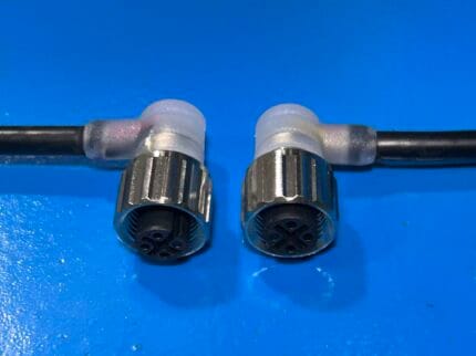
- Consider a right-angle head – a 12-way straight connector is deep and often fouls a machine guard.
- Molded strain relief carries the weight of a thicker bundle; a clamp will not hold twelve conductors the way an overmold will.
The M12 shell is the same size whatever the position count, which is why the coding and the pin count have to be read together when you identify a replacement.
How to specify one
The cleanest way is to send the device pinout and the function of each conductor – signal, differential pair, supply or earth. If that is not available, send the device model and the existing cable; we can reverse-engineer the pinout from a sample and build a replacement. Length, jacket and whether the run moves are the remaining questions.
We will propose a core layout from your pinout and confirm it before the first article is built. Every assembly is continuity tested and inspected at the connector before it ships.
Typical applications for this M12 12 pin cable
- Multi-turn absolute encoders and resolvers on servo axes – see also our encoder feedback cable with PUR jacket
- Valve manifolds with eight or more solenoids
- Multi-channel I/O blocks and remote peripheral modules
- Machine-vision lighting and camera combinations on one connector
- Panel feed-throughs using our M12 12-pin bulkhead cable with flying leads
- Dense servo feedback runs alongside our custom servo motor cable assembly
What we need from you
- Pinout with the function of each conductor, or a sample to reverse-engineer
- Current on the supply cores
- Length, and whether the run is fixed or moving
- Straight or right-angle, and on which end
- Jacket and shielding requirements
- Quantity, and whether you need a first article
Workmanship and testing
Every build is assembled and inspected to IPC/WHMA-A-620 Class 3 workmanship under our ISO 9001 system. We terminate conductors from 32 to 12 AWG. Each unit is checked for continuity and pinout before packing, and where the build carries an ingress rating we can add seal checking on the production run.
Custom builds and ordering
Prototypes run from 5 pcs with a 3 working day turnaround; volume orders start at MOQ 500 pcs and ship 14 working days after sample sign-off. If the build needs tooling we do not already hold, add roughly 10 working days. OEM and ODM orders ship under your part number and labeling, and material certificates and first-article reports are available on request.
Related high-density and M12 assemblies
- M12 8-pin A-coded IP67 waterproof extension cable
- M12 8-pin A-coded right-angle / straight extension cable
- USB Type-C to M12 8-pin industrial cable
- M12 Hybrid SPE cable for actuators and valve islands
- M12 drag chain cable for continuous flexing
- M12 A-coded straight or right-angle extension cable
Full range: Circular M8 and M12 cable assemblies.
Frequently Asked Questions
Can you build 12 positions on other codings?
Twelve positions is an A-code arrangement. Other codings have their own position limits – tell us the device port and we will confirm what is available.
What if I do not have the pinout?
Send the existing cable or the device model. We can reverse-engineer the pinout from a sample and confirm the layout with you before building.
Is a right-angle version available?
Yes, and on a 12-way connector it is often the better choice – the straight body is deep and can foul a guard or an adjacent port.
Do you mix conductor sizes in one bundle?
Yes. Signal cores and supply cores are sized separately, which is the usual reason to specify a custom build rather than buy a catalog cordset.
| Connector A | M12 A-coded 12-pin, straight or right-angle |
|---|---|
| Connector B | M12 A-coded 12-pin, or open leads |
| Coding | A-code, high density |
| Positions | 12 – other counts from 2 to 17 on request |
| Conductors | Shielded multi-core, mixed signal and supply sizes |
| Jacket | PUR or PVC |
| Shielding | Braided overall screen with drain wire |
| Ingress rating | IP67 when mated – confirm per build |