USB-C Power Display Cable 240 W PD 3.1 with Digital W/V/A Readout
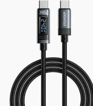
A usb-c power display cable with a digital W/V/A readout in the plug, so you can see the negotiated PD 3.1 operating point and the actual draw. E-marked, aluminum shell, 1 m and 2 m. Built to the power level you name, and verified on the bench.
Last updated: 13 September 2026
Overview
A usb-c power display cable answers the question a charging icon never does. A phone or laptop reports that it is fast charging and that is the end of the information: not which voltage the charger settled on, not how much current is actually flowing, and not whether the pair quietly dropped to a lower operating point because something in the chain could not hold the higher one. This cable puts a small digital module in the plug body that reports watts, volts and amps as they happen.
Key Specifications
| Connector A | USB-C plug with aluminum shell and integrated display module |
|---|---|
| Connector B | USB-C plug with aluminum shell |
| Display | Cycling digital readout of watts, volts and amps |
| Power specification | USB Power Delivery 3.1 including extended power range |
| Rated power | Up to 240 W at the top of the extended power range, subject to confirmation |
| E-Marker | Marker chip in the plug reports the cable rating to the charger |
| Lengths | 1 m / 2 m |
| Applications | Charging diagnostics, test benches, field service, mixed charger fleets |
| Shell | Aluminum, better heat dissipation than a plastic body |
| Build note | Operating point reached depends on charger and device; stated per your spec |
What PD 3.1 EPR actually changes
Power Delivery negotiates an operating point between charger and device rather than pushing a fixed voltage. The 3.1 revision added an extended power range above the older 100 W ceiling, which is where the 240 W figure comes from. The table below sets out the standard range and the extended one as they are defined in the specification.
| Range | Operating voltages | Max current | Top power |
|---|---|---|---|
| Standard power range | 5 / 9 / 15 / 20 V | 3 A (5 A on 20 V) | 100 W |
| EPR – 28 V | 28 V | 5 A | 140 W |
| EPR – 36 V | 36 V | 5 A | 180 W |
| EPR – 48 V | 48 V | 5 A | 240 W |
Reaching the top of that table is not a property of the cable alone. Three things have to agree: the charger has to offer the higher operating point, the cable has to report that it is rated for it, and the device has to ask for it. If any one of the three is missing, the pair settles lower and charging still works, just more slowly. That is a design feature, not a fault.
The E-Marker, and why it is not optional above 3 A
An E-Marker is a small chip in the plug that identifies the cable to the charger: its current rating, its voltage rating and its vendor. The USB-C specification requires a cable to be electronically marked once it is carrying more than 3 A, which is why every cable sold above 60 W carries one. Without it, a charger that could deliver 240 W has no way of knowing whether the cable in between can take it, so it refuses and falls back to a lower point.
Practical consequence for a buyer: if a high-power charger is delivering less than you expect, the cable is the first suspect and the E-Marker is the first thing to check. This build carries the marker in the plug, and the rating it reports is the value stated per your specification.
Reading the display
The module cycles through the three measurements rather than showing them all at once, which keeps the readout legible in a small window. All three are useful, and they answer different questions.
| Reading | What it tells you | How to use it |
|---|---|---|
| Watts | The real delivered power – the product of the other two | Read this first. It is what the device is actually receiving. |
| Volts | Which operating point the pair agreed on | A low reading means they settled low, not that the charger is faulty. |
| Amps | The instantaneous draw of the load | Use it to see startup peaks and charge taper. |
Why the numbers move, and when that is normal
Expect movement; a static reading would be more suspicious than a moving one. A device near full charge tapers its current, so watts falls while volts stays where it was – that is charge management, not a fault. A device in standby or already topped up can show a watt figure low enough to look like nothing is happening, and at very light load the display can look unstable because there is very little current to measure.
What is worth investigating is a volts reading that sits lower than the charger is capable of: that is the signature of a negotiation that fell back, and the causes in order are the cable rating, the charger capability, and the device request.
Refresh rate, resolution and accuracy at the low end are figures we confirm rather than assume, and they are stated per your specification after sample testing.
Build
The plug bodies are aluminum, which dissipates the heat generated at the contacts better than a plastic shell and survives being dropped on a workshop floor. The display module is potted into the shell so it does not rattle loose. Stock lengths are 1 m and 2 m: short for a bench or a power bank, longer for a desk where the socket is not adjacent. Where the run needs to be longer than 2 m, remember that a passive cable at high current is a voltage-drop question as much as a convenience one.
Typical applications for this usb-c power display cable
- Test benches verifying what a charger and device actually agreed on
- Field service bags, where it is quicker than carrying a meter and a breakout board
- Mixed charger fleets, to find which chargers are under-delivering
- QA sampling of incoming chargers and power banks
- Integration work alongside a USB-C PD trigger cable on a DC project
- Comparison testing against a standard USB-C PD charging cable
How to specify your build
- Length – 1 m or 2 m, or a build-to-order length.
- Power level you need to reach, stated per your specification.
- Marker rating the plug should report.
- Readout – which measurements, and the cycling order.
- Shell finish and any marking you want on it.
- Data capability, if the cable has to carry more than power.
- Quantity, sample or production.
Workmanship and testing
Workmanship follows IPC/WHMA-A-620 Class 3 and the line runs under ISO 9001. Conductors from 32 to 12 AWG are in range. Continuity and pinout are verified on 100% of units before packing; if you specify an ingress rating, seal checking on the batch can be quoted.
Custom builds and ordering
Prototype builds start from 5 pcs and ship in 3 working days; production orders start at MOQ 500 pcs and ship 14 working days after approval. New overmold tooling adds about 10 working days. OEM and ODM builds ship under your part number and labeling, with material certificates and first-article reports available on request.
Related USB-C and DC assemblies
- USB-C PD Charging Cable 240 W PD 3.1 EPR, Braided
- USB-C PD Trigger Cable to DC 5.5×2.1mm
- USB-C PD Trigger Power Cable to DC 5.5×2.1mm Barrel
- 240 W Magnetic USB-C Charging Cable, 16-Pin Rotating Head
- USB-C to DC 5521 Right Angle Cable
- IP67 DC to USB-C Cable, 5.5×2.1mm Barrel Power Lead
Full range: DC plug power cable assemblies.
Frequently Asked Questions
Why am I not seeing 240 W?
Three things have to agree: the charger offers it, the cable reports it, and the device asks for it. Missing any one and the pair settles at a lower operating point.
What is the E-Marker for?
It tells the charger what the cable is rated for. Above 3 A the specification requires one, so an unmarked cable will hold a high-power charger back.
Why does the watt reading drop as my device charges?
Charge management tapers current near full. Volts stays put and watts falls – that is normal, not a fault.
Can the display show all three values at once?
The module cycles through watts, volts and amps to keep the readout legible in a small window. Cycling order can be set on a production build.
Does this cable carry data as well as power?
Tell us what the build has to carry. Power-only and full data builds are both possible, and the conductor set is different.
| Connector A | USB-C plug with aluminum shell and integrated display module |
|---|---|
| Connector B | USB-C plug with aluminum shell |
| Display | Cycling digital readout of watts, volts and amps |
| Power specification | USB Power Delivery 3.1 including extended power range |
| Rated power | Up to 240 W at the top of the extended power range, subject to confirmation |
| E-Marker | Marker chip in the plug reports the cable rating to the charger |
| Lengths | 1 m / 2 m |
| Applications | Charging diagnostics, test benches, field service, mixed charger fleets |
| Shell | Aluminum, better heat dissipation than a plastic body |
| Build note | Operating point reached depends on charger and device; stated per your spec |