Lightweight UAV Wire Harness for eVTOL Propulsion and Avionics Bays
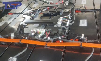
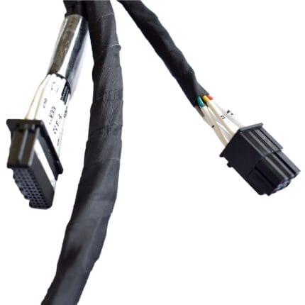
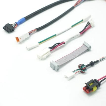
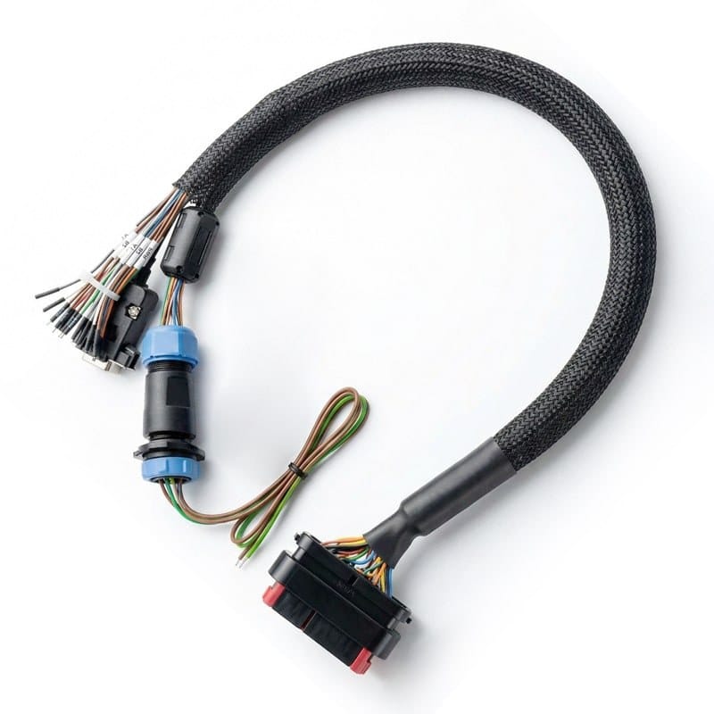
A lightweight UAV wire harness built to the mass budget on your drawing, for eVTOL propulsion feeders, battery interconnects and avionics bays. Finished weight is recorded against each serial number, so the aircraft weight and balance file holds a measured value.
Last updated: 13 September 2026
Overview
On an electric vertical take-off aircraft every gram of loom comes straight out of payload or range. A lightweight UAV wire harness is therefore not a standard harness with thinner wire in it: the mass question runs through the conductor, the insulation, the screen, the sleeving and even the marker system, and each of those carries a cost. We build to the mass budget on your drawing and report the actual finished weight against the serial number, so the aircraft weight and balance record holds a measured value instead of an estimate.
Key Specifications
| Build Type | Build to drawing or build to sample |
|---|---|
| Wire Style | MIL-W-22759 style ETFE or PTFE insulation |
| Conductor | Silver-plated or nickel-plated copper |
| Screening | Metallized or lightweight braid options |
| Applications | Propulsion feeders, battery interconnects, avionics, gimbal |
| Workmanship | IPC/WHMA-A-620 Class 3 criteria when specified |
| Traceability | Batch records on wire, contacts and sleeving |
| Testing | Continuity, dielectric withstand, crimp pull test |
Before arguing about wire gauge it helps to know where the mass is. On a typical airframe loom the order looks like this:
| Element | Share of the loom mass | Practical reduction |
|---|---|---|
| Conductor | The largest single contributor | Right-sizing each leg rather than running one common gauge across the loom |
| Screen | Second, on screened legs | Metallized tape or a high strength light braid instead of standard copper braid |
| Insulation and jacket | Significant on long feeders | Thin-wall ETFE or PTFE constructions instead of general purpose insulation |
| Sleeving and protection | Adds up over a long route | Protection only where the loom actually rubs, not over the whole run |
| Markers and hardware | Small per item, but there are many items | Lightweight marker sleeves and clamp spacing optimized rather than minimized |
The last two rows are where most programs find weight they did not expect, because they are usually specified by habit rather than by calculation.
Every gram saved is paid for somewhere. These are the trades we put in front of customers most often:
| Measure | What you gain | What you give up |
|---|---|---|
| Thinner conductor per leg | Real mass reduction | Less margin if the current profile changes later; needs the per-leg current on the drawing |
| Lightweight screen | Meaningful saving on screened legs | Lower coverage than a heavy braid, so it has to be checked against your noise environment |
| Thin-wall insulation | Saving over long runs | Less mechanical protection at rub points; add local sleeving instead |
| Fewer clamps | Mass and installation time | More unsupported length between supports, which vibration will find |
| No overall jacket on branches | Mass at branch level | The bundle is less protected during installation and service |
We do not make these calls for you. We lay them out, you choose, and we build to the choice. If a choice looks likely to fail a vibration check, we say so at quotation stage rather than after delivery.
Vibration, clamping and the route
An airframe loom is a vibration problem before it is a wiring problem. What decides whether it survives is usually not the cable but the support: clamp spacing, clamp type, whether the loom is supported at every breakout, and whether a heavy connector is carried by the loom or by the structure. On an unmanned aircraft the nearby structure is often a thin composite panel, so the anchor points are fewer than a drawing suggests. We build to the clamping interval and strain relief method on your drawing, and we flag any place where the layout makes that hard to achieve. The common one is a branch leaving the main bundle where there is no structure within reach to clamp to.
Segregation inside a single loom
Propulsion feeders and flight control wiring want separation, and where they have to share a loom the separation has to be designed rather than hoped for. We route high current feeders away from the flight control legs, hold crossover angles where the drawing puts them, and terminate screens per leg rather than gathering them. Where your program references SAE AS50881 routing practice, we build to it as specified and note any point where the airframe geometry makes literal compliance impossible.
Typical applications for this lightweight UAV wire harness
- Propulsion feeders from the battery bus to the motor controllers
- Battery to battery interconnects
- Avionics and flight control looms
- Gimbal, sensor and payload wiring
- Ground test and iron bird looms built to the same drawing
Traceability and records
Airframe programs arrive with their own inspection plan and first article requirements, and we build to the plan you supply. Work follows IPC/WHMA-A-620 Class 3 workmanship criteria when that is what the drawing names, and we keep batch traceability on wire, contacts and sleeving. Weight per assembly is recorded rather than estimated, which matters once the aircraft has a weight and balance file to maintain.
Options worth discussing early
- Embedded fiber along a feeder run for strain or temperature sensing
- Repairable break points at bay boundaries so one damaged leg does not ground the airframe
- Connector backshells and strain relief matched to the airframe mounting points
- Separate part numbers per loom so a payload change does not force a full re-loom
Custom builds and ordering
A prototype lot of 5 pcs ships in 3 working days; series orders start at 500 pcs and ship 14 working days after sample approval. We hold 100 sets of mold tooling in house, so a standard body needs no tooling time and a new one adds about 10 working days. OEM and ODM builds go out under your part number and label, with material certificates and first-article reports on request.
Frequently Asked Questions
Can you quote to a mass target rather than a drawing?
We can quote to a target, but we build to a drawing. Give us the mass budget and the current per leg and we will propose a construction; once you approve it, that becomes the drawing.
Do you weigh each assembly?
Yes, where the drawing asks for it. Finished weight is recorded against the serial number and supplied with the shipment.
What screen options suit a lightweight build?
Metallized tape screens and high strength lightweight braids in place of standard copper braid. Coverage is lower, so we check it against your noise environment before committing.
How fast is a prototype loom?
Five pieces minimum, shipped in 3 working days from an approved drawing. A physical sample from an earlier build stage is often the fastest route to an accurate quote.
Related assemblies
- Micro-D Shielded Jumper with Twisted Pair and Coax Mix for Avionics
- Single Pair Ethernet Cable in M8 and M12 Shells for Sensor Runs
- 10BASE-T1L Patch Cord for Single Pair Ethernet, T1 Industrial or M8
- M12 CAN Bus Cable, 5-Pin Shielded Pair for CANopen and DeviceNet
- Encoder Feedback Cable with PUR Jacket for Digital Servo Loops
- Cobot Arm Cable Harness with Drag-Chain Jacket
Full range: Custom Wire Harnesses.
| Build Type | Build to drawing or build to sample |
|---|---|
| Wire Style | MIL-W-22759 style ETFE or PTFE insulation |
| Conductor | Silver-plated or nickel-plated copper |
| Screening | Metallized or lightweight braid options |
| Applications | Propulsion feeders, battery interconnects, avionics, gimbal |
| Workmanship | IPC/WHMA-A-620 Class 3 criteria when specified |
| Traceability | Batch records on wire, contacts and sleeving |
| Testing | Continuity, dielectric withstand, crimp pull test |