A right-angle cable assembly exists because the machine does not care how elegant the routing looks. When a connector has to leave a panel parallel to the wall, pass under a lid with 12 mm of clearance, or exit a camera gimbal without being levered out by its own cable weight, a straight plug becomes the problem and a 90-degree exit becomes the spec. This page is the manufacturing and sourcing companion to our in-depth selection guide: the forms we build, how each family turns the corner, the drawing language that prevents a wrong-axis build, the tooling and shielding that make it survive, and the parameters to put on a purchase order.
If you are still deciding whether the connector should be right-angle at all, start with the 12,000-word guide instead and come back. What follows assumes the decision is made and you are now buying or specifying a build — the implementation differences, the tolerance you can actually hold, and the lines that belong on a drawing.
Right-angle vs straight: the 30-second version
Buyers reach for a right-angle build for one of three reasons, none aesthetic: clearance (a straight plug needs its full length plus a bend radius behind the panel, a right-angle exit needs only the body depth plus cable diameter), cable dress (the cable leaves flat against a chassis instead of looping out), or strain relief (the exit angle reduces the lever arm that pries the connector loose). The deep guide covers the “should”; here we cover how it gets built and bought.
The right-angle product family
Right-angle is a modifier that applies to roughly eight connector families we build, and each turns the corner differently.
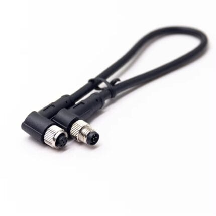
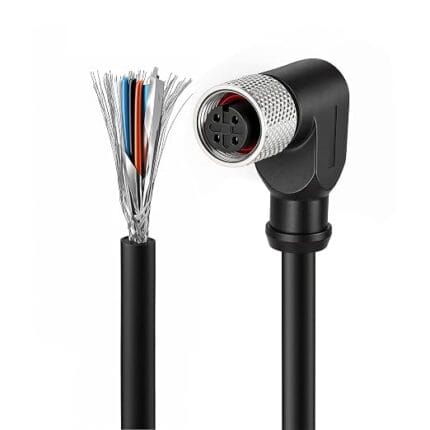
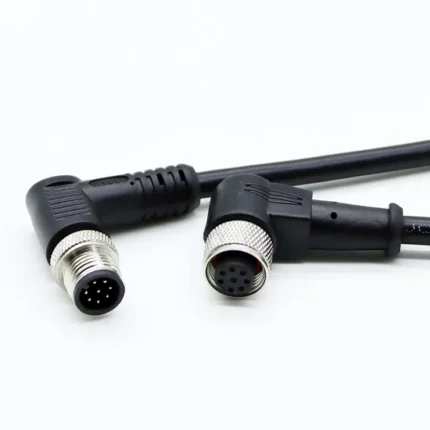
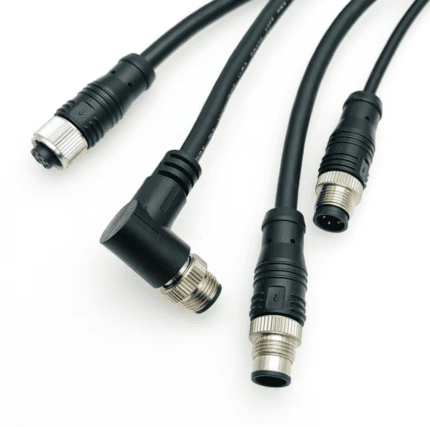
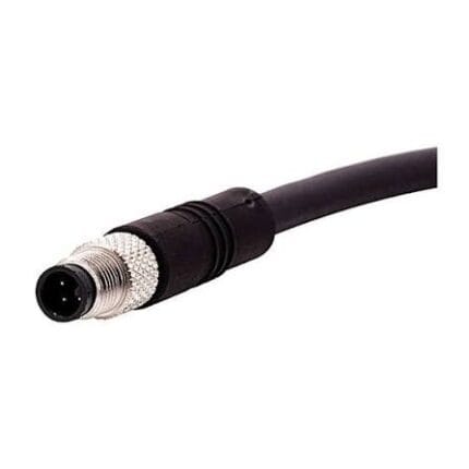
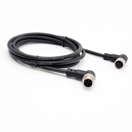
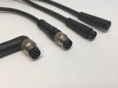
- Circular sensor and fieldbus (M8/M12). The workhorse of factory automation. An M12 4-pin A-coded right-angle shielded sensor cable and an M8 6-pin A-coded right-angle sensor cable let a sensor cable hug a machine frame. Where one end stays straight and the other folds, the M12 8-pin A-coded right-angle/straight extension cable covers mixed routing, and the M12 A-coded PVC/PUR straight-or-right-angle extension cable matches the jacket to the environment. A gray PUR washdown version is the M8/M12 5-pin right-angle PUR sensor cable.
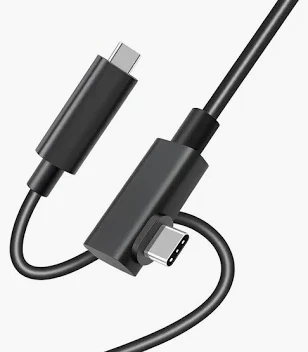
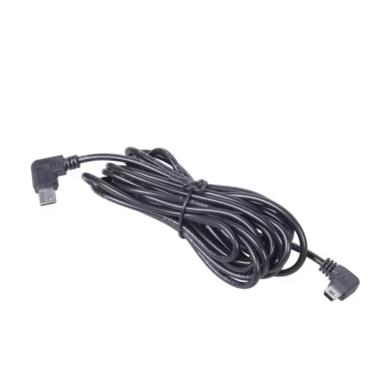
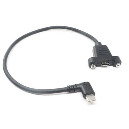
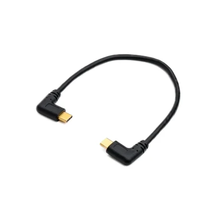
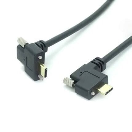
- USB-C, data and screw-lock. The right-angle USB-C cable and the car USB-C data cable with a right-angle plug sit flat against a panel or dashboard. For vibration, screw-lock variants add retention: the right-angle USB Type-C male-to-male screw-lock cable and the right-angle Type-C male to female socket with screw-lock.
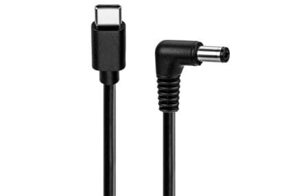
- DC power, barrel plugs (5521 and 4017). Right-angle barrels keep a power cord from standing off the back of a device. The USB-C to DC 5521 right-angle cable, DC 4017 right-angle power cable, and DC 4017 straight-to-right-angle combo cable cover the common footprints; the DC 5521 right-angle-to-straight adapter cable bridges orientations. The threaded locking DC pigtail with a shielded right-angle plug adds a thumbscrew collar over the 5.5 x 2.1 mm barrel.
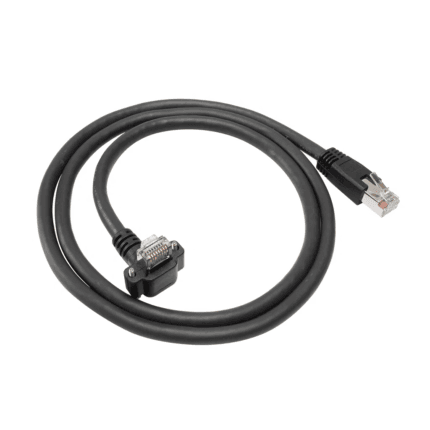
- RJ45 screw-lock. Industrial Ethernet exiting a cabinet face without a tail uses a right-angle die-cast plug: the right-angle RJ45 screw-lock cable (Cat6A S/FTP).
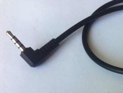
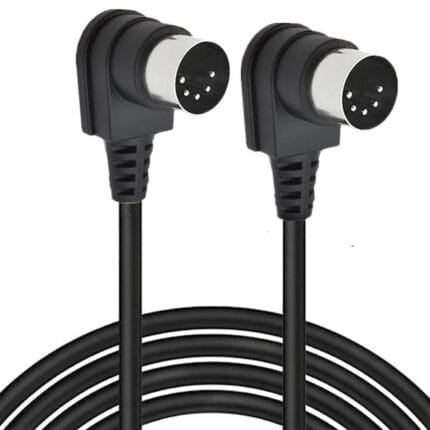
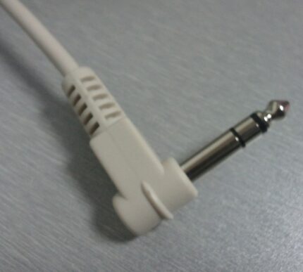
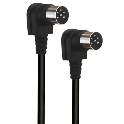
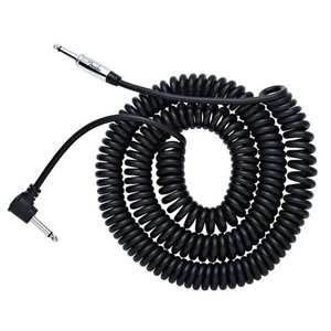
- Audio, TRS/TRRS and DIN/MIDI. Pedalboards and rack gear all hit the same wall: jacks too close together for a straight plug. The 6.35 mm TRS 90-degree audio cable and the 3.5 mm TRRS 4-pole right-angle cable solve jack spacing; the 5-pin DIN dual right-angle MIDI cable and the 6-pin DIN male-to-male dual right-angle cable fold both ends.
- Hybrid fiber. The VR link cable with a 90-degree headset end runs a 5 m hybrid fiber build with a clean headset exit.
The common thread: “right-angle” is a build decision, not a part number, and the same family can be turned two different ways.
How each connector family turns the corner
There are two mechanically distinct ways to get a 90-degree exit, with very different cost, size and sealing consequences. Molded right-angle forms the housing itself at 90 degrees in the injection tool, so the cable leaves at the angle with no extra joint. Assembled or adapter right-angle bends the exit of a straight plug through a separate elbow or screw-on angled backshell. Molded is smaller and seals better; assembled is cheaper to add to an existing straight platform but adds length and a leak or snag point.
| Connector family | Typical right-angle build | Turn mechanism | Size and protrusion note |
|---|---|---|---|
| M8 / M12 circular (A-coded) | Molded 90-degree backshell | Mold-formed housing | Adds near-zero length beyond the plug; sealed to IP67 |
| M12 extension (8-pin) | Right-angle one end, straight the other | Mold-formed housing | Exit angle set at tooling, not adjustable after |
| USB Type-C | Right-angle overmold, or screw-lock housing | Mold plus strain relief | Strain relief becomes part of the 90-degree bend |
| DC barrel (5521 / 4017) | Right-angle molded barrel, or straight-to-right elbow | Mold, or elbow adapter | Adapter route adds 12–18 mm of protrusion |
| RJ45 screw-lock (Cat6A) | Right-angle die-cast thumbscrew plug | Assembled housing, not molded | Die-cast body adds depth |
| Audio TRS / TRRS / DIN | 90-degree molded plug; dual right-angle for MIDI | Mold-formed plug | Slim body fits jack-to-jack spacing |
| Hybrid fiber (VR) | 90-degree headset end over hybrid cable | Mold over fiber + copper hybrid | Exit angle protects the fiber bend at the headset |
The practical rule: if the application is sealed, vibrated, or clearance-critical, molded right-angle wins, because the elbow adapter is where a straight-to-right conversion picks up length, cost and a second retention interface. If you are adding right-angle to a connector you already qualify as straight, the adapter route gets you there without new tooling.
The drawing language: exit direction, angle, length
A wrong-axis build is the most expensive mistake in right-angle sourcing, because the part is correct in every other way and still does not fit. Three annotations eliminate it.
| Drawing element | What to state | Typical tolerance we hold | Why it matters |
|---|---|---|---|
| Exit direction | “Cable exits toward the front panel, downward,” or a clocking reference | Must be unambiguous, stated once | Wrong axis = unusable assembly |
| Exit angle | 90 degrees nominal | ±5° standard, ±3° on request | Fits the mounting envelope without side load |
| Clocking / orientation | Exit direction relative to the keyway or pin 1 | ±5° on molded bodies | Keeps polarization and dress consistent |
| Molded exit length | Distance from connector rear face to where the cable straightens | ±2–3 mm | Sets strain relief and bend placement |
| Overall cable length | Mating face to opposite mating face | Per IPC/WHMA-A-620 class | The harness has to reach, not stretch |
| Strain relief / bend retention | Overmold length and material | Specified at RFQ | Decides flex life at the exit |
The most common omission is clocking: a buyer writes “90-degree M12” and the shop molds it exiting toward pin 1 when the panel needed pin 4. State the exit direction against the keyway, not “up” or “down,” because “up” changes with how the operator holds the drawing. Our wire harness drawing checklist walks through the rest, and how to prepare a custom cable assembly RFQ turns them into a quote-ready package.
The manufacturing chain
A right-angle assembly is mostly a standard assembly with one harder step: the corner itself. The chain that matters is overmolding, shield termination, and backfill.
Overmolding and the corner tool
Molded right-angle connectors run on the same injection platform we document in our overmolding and injection page, but the cavity geometry differs: the cable loads at 90 degrees to the insert, so the gate position and strain-relief length must keep the bend clear of the melt front. The result is a strain relief that is part of the bend rather than a sleeve added after it. When a family has no existing right-angle cavity, it is cut on our mold making and tooling line and quoted as a separate NRE line item; if the cavity exists, tooling is amortized and the unit price behaves like a standard overmold. That is why the same “right-angle M12” can quote differently from two suppliers — one is cutting a new cavity, the other is not.
Shield termination at the corner
A 90-degree exit is where a foil or braid wants to open, because the shield must be dressed around the bend and terminated inside the housing without losing 360-degree contact. We dress the braid around the cable at the backshell and run the drain along the bend on shielded builds such as the M12 right-angle shielded sensor cable and the Cat6A S/FTP right-angle RJ45 screw-lock cable. The rule is the same one in our shielded vs unshielded cable article: a shield grounded at one point or broken at the bend becomes an antenna. For signal-critical audio and fieldbus, the drain is soldered or crimped at the shell rather than floated.
Potting and backfill
Where the corner must survive washdown, vibration or a flexing service loop, the housing interior is potted or backfilled after termination. The compound sets the bend so the solder joints cannot work-harden and the shield cannot migrate. Potting is standard on right-angle DC and screw-lock power builds, and it lets a right-angle plug carry the same rating as its straight twin instead of derating at the bend.
Validation and reliability
Right-angle assemblies are tested on the same line as our straight builds — see our testing and validation page — but three checks get extra weight at the corner:
- Pull and flex at the exit. The strain relief is pulled and cycled at the bend, where a molded right-angle fails first if the overmold is too short.
- Continuity and shield resistance after bending. Measured before and after bend cycling to confirm the 360-degree termination did not open.
- Ingress at the mold line. For sealed builds, the mold parting line and the exit are the two leak paths, so IP verification concentrates there.
For a sealed outdoor or washdown build, the same leak-path logic in our waterproof cable assembly article applies — the corner is one more place water wants in, and the potting or overmold keeps it out.
What to put on the purchase order
The difference between a right-angle assembly that fits first try and one that goes back for rework is almost always the RFQ, not the factory. At minimum the drawing should carry the exit direction, exit angle, clocking against the keyway, overall length, connector family and coding, jacket compound, and whether the shield is drained or floating. Our overmolded cable design article expands on the fields engineers leave blank, and how to specify an overmolded cable assembly covers material and IP choices. The M12 coding guide, USB-C cable versions and PD, and DC power barrel plug selection articles are the family-specific references.
Frequently asked questions
Can you mold a right-angle onto any connector, or only certain families?
Only where a right-angle insert and cavity exist or can be cut. Circular M8/M12, USB-C, DC barrel, TRS/TRRS/DIN and the RJ45 screw-lock families are the ones we run regularly. For a connector we have not molded right-angle before, the cavity is quoted as a one-time NRE item.
What is the difference between a molded right-angle and a straight plug plus an elbow adapter?
Molded forms the housing at 90 degrees in the tool, so the cable leaves at the angle with no extra joint and seals cleanly. An elbow adapter screws a bend onto an existing straight plug, adding roughly 12–18 mm of protrusion and one more potential leak or snag point. Molded is the default for sealed, vibrated or clearance-critical builds; the adapter is the fast way to add right-angle to a platform you already qualify as straight.
How do I state the exit direction and angle so there is no ambiguity?
State the exit direction against the keyway or pin 1, not “up” or “down,” and state the angle once. “Cable exits at 90 degrees, toward pin 4” is unambiguous; “90-degree M12” is not. Add a clocking reference and the shop cannot build it on the wrong axis.
What exit-angle tolerance can you hold on a molded right-angle?
±5 degrees as standard on molded bodies, with ±3 degrees available where the mounting envelope is tight. Adapter-based right-angles inherit the tolerance of the elbow itself, which is usually looser.
Does a right-angle connector change the current or voltage rating?
Not from the geometry alone. The derating risk at a right-angle is mechanical — a broken shield or a flexed joint — not electrical. A molded or potted right-angle carries the same rating as its straight twin; an adapter adds an extra contact interface, which is where any added resistance lives.
Can a right-angle build still be sealed to IP67 or IP68?
Yes, when it is molded or potted. The mold parting line and the cable exit are the two leak paths, both sealed in a molded right-angle. An elbow adapter adds a third interface, which is why sealed builds rarely use it.
How do you terminate the shield on a right-angle connector?
The braid is dressed around the cable at the backshell and terminated for 360-degree contact, with the drain soldered or crimped at the shell rather than floated. At the 90-degree bend the shield is the first thing to open, so the bend is where the termination gets the most attention.
What is the minimum order quantity and tooling cost for a custom right-angle assembly?
If the family already has a right-angle cavity, there is no new tooling and MOQ behaves like a standard overmold. If a new cavity has to be cut, tooling is quoted as a separate NRE line item before production. We quote tooling separately so the unit price you compare is the recurring cost.
What cable lengths and gauges do you support for right-angle assemblies?
Length is cut to your drawing from the mating face to the opposite mating face, and gauge follows the application — the same sizing as a straight build. The exit angle does not constrain length or gauge; it only changes the bend and strain-relief geometry at the connector.
What do you need from me to quote a right-angle harness?
A drawing with exit direction, exit angle, clocking against the keyway, overall length, connector family and coding, jacket compound, and shield termination (drained or floating). From that we return a quote with tooling called out separately if a new cavity is required. The full field list is in our custom cable assembly RFQ article.
Get a quote
If you already know the connector family and the exit direction, send the drawing — our engineering team will confirm the clocking, the exit-angle tolerance we can hold, and whether the build needs a new cavity. If you are still choosing between straight and right-angle, read the right-angle vs straight guide first. For the full picture of what we build and how, start at our cable assembly overview or tell us which industry the build serves — industrial automation, automotive and EV, broadcast and pro AV, test and measurement, or marine and outdoor.
Product range
These are the right-angle cable assemblies we stock and build to order. Each listing shows the exit direction and connector family; any can be modified for length, angle, or shielding.
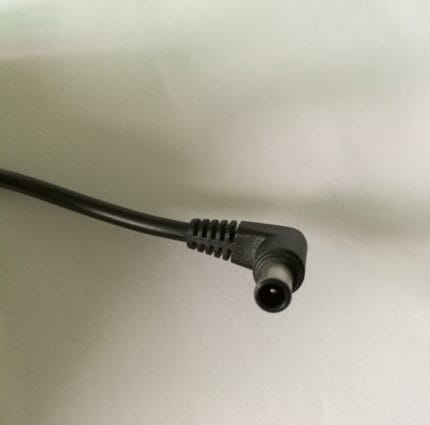
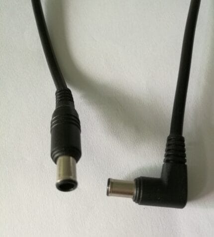
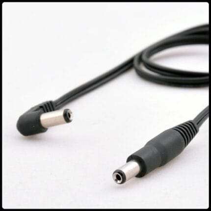
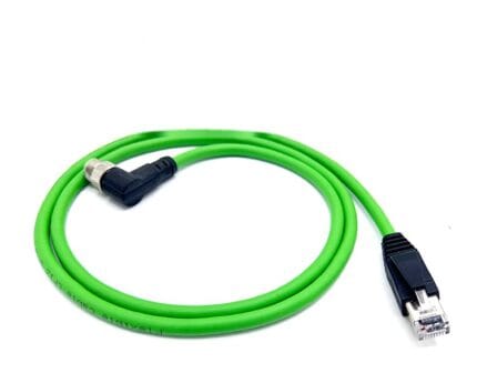
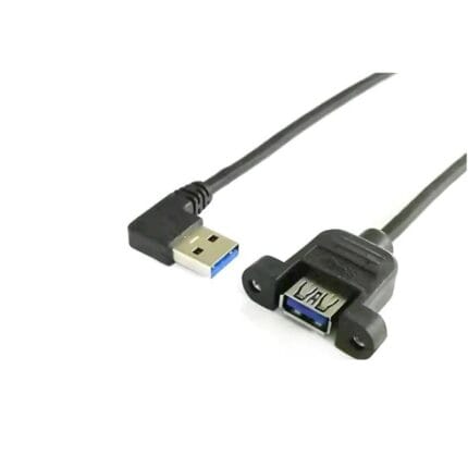
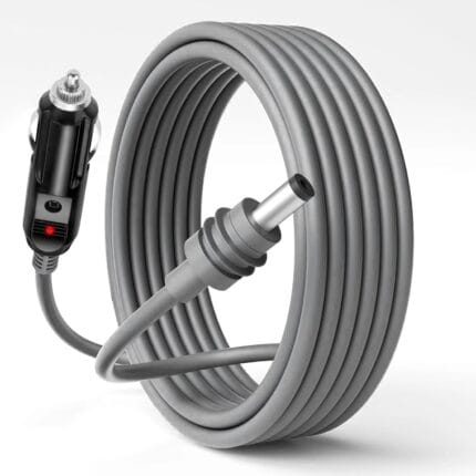
Threaded Locking DC Pigtail 5.5×2.1mm, Shielded Right-Angle Plug to Bare Wire
A threaded locking dc pigtail for equipment that vibrates: a 5.5x2.1mm right-angle plug with a knurled threaded collar, shielded cable with a drain wire, and tinned tails. The collar screws onto a matching socket, so retention no longer depends on friction. 2.00 m standard, with the cable exit clocked to your run.