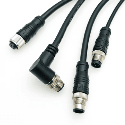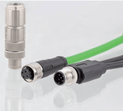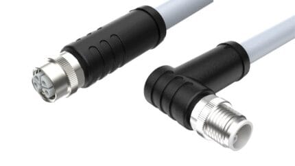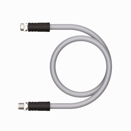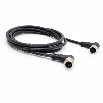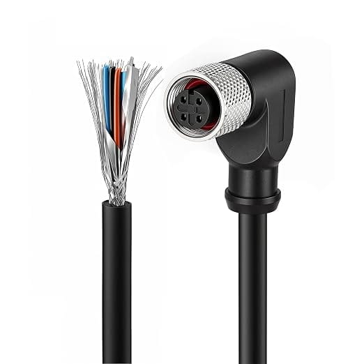
M12 4-Pin A-Coded Right-Angle Shielded Sensor Cable
This M12 4 pin shielded cable carries analog and sensor signals past variable frequency drives without the noise that ruins an unshielded drop. Foil plus braid screen, right-angle A-coded female body, 24 AWG conductors, bonded to the coupling nut per your drawing.
Overview
An M12 4 pin shielded cable earns its keep in one situation: the signal is small, the run is long, and something nearby is switching hundreds of amps. This build puts a foil screen plus a braid around four 24 AWG conductors, brings the screen through to a right-angle female connector, and bonds it the way your drawing says rather than the way the last assembler found convenient. Getting the screen termination right matters more than choosing the shield structure, and it is the part most often left off the specification.
Key Specifications
| Connector | M12 4-pin A-coded right-angle female |
|---|---|
| Interface standard | IEC 61076-2-101 |
| Rated voltage | 250 V AC/DC |
| Rated current | 4 A per pin |
| Conductor | 4 x 24 AWG stranded |
| Shielding | Foil plus tinned copper braid (S/FTP style) |
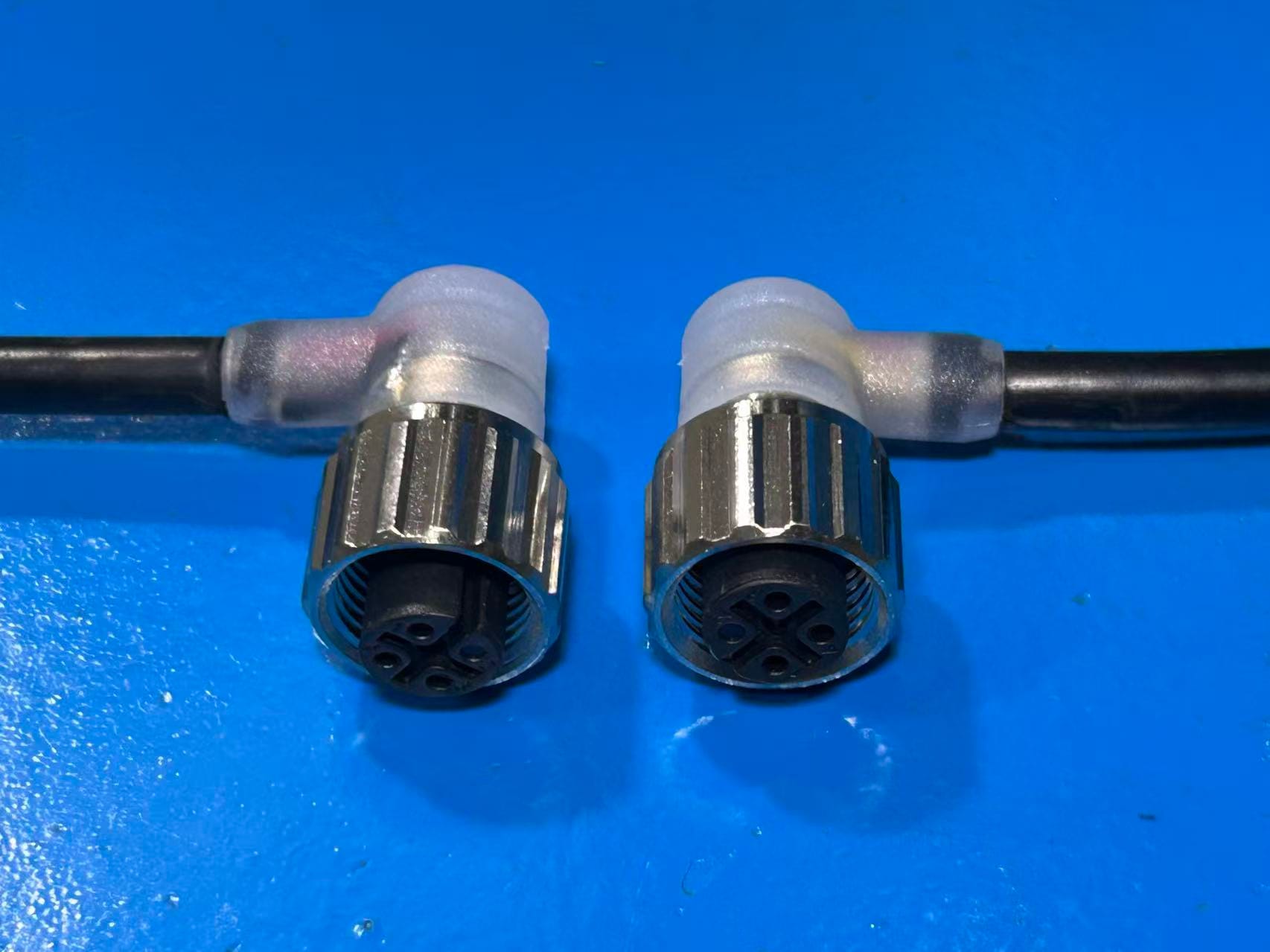
| Inner mold | PE inner mold before the outer overmold |
| Jacket | PVC |
| Operating temperature | -25 to +85 °C |
Why shield a sensor drop at all
An unshielded twisted conductor running next to a servo drive will pick up whatever the drive is emitting, and electromagnetic interference does not announce itself: it shows up as counts that arrive when nothing is in front of a photo eye, as an analog channel that drifts with motor load, or as a communication port that drops frames only when the spindle is running. Once you have chased that kind of fault you stop treating shielding as an optional line item.
Foil, braid or both
The two structures do different work, which is why this build carries both. Foil is good against high frequency fields and gives close to full coverage, but it is thin, has poor current-carrying ability, and does not survive repeated flexing on its own. Braid is mechanically tough, handles the low frequency end better, and gives a low resistance path for interference current, but coverage depends on weave tightness.
| Structure | Good against | Weak where |
|---|---|---|
| Foil screen only | High frequency capacitive coupling, cost sensitive static runs | Flex duty, low return path resistance, termination repeatability |
| Braid only | Low frequency magnetic fields, heavy mechanical duty | Very high frequency without dense weave, weight and diameter |
| Foil plus braid | Wide band noise plus a low resistance return path | Cost, diameter, and termination labor |
| Unshielded twisted pair | Balanced low frequency pickup where the load is differential | Anything running alongside power conductors for any distance |
Where the screen should land
This is the decision that actually determines whether the shield does anything. A screen that is not terminated is an antenna that is connected to one end of the circuit only.
| Termination | What it gives you | Order it when |
|---|---|---|
| 360 degree bond to the coupling nut | Metal-to-metal contact all round, lowest transfer impedance | The device and the receptacle are both metal shell, which is the common case |
| Drain wire terminated at one pin | Simple, cheap, multiplexes the screen onto an existing contact | The device specifies it, or the interface has no metal shell |
| Bond at one end only | No ground loop current in the screen | Sensitive low frequency analog where the two ends are at different earth potentials |
| Bond at both ends | Best high frequency performance | Short runs inside one cabinet where there is a common reference plane |
| Hybrid: bond both, add a parallel conductor | High frequency shield plus controlled low frequency path | Confirm at order against your installation drawing |
The right-angle decision
A right-angle body buys back the clearance that a straight connector plus its minimum bend radius consumes, typically several centimeters of protrusion at the device. The trade is that you now have to specify which way the cable leaves the connector, because the body can be clocked in several directions and only one of them clears the neighboring port. Tell us the exit direction on the drawing; if you are unsure, send a photo of the device face in situ.
How to verify the shielding actually worked
Two checks that cost nothing and catch most problems. Continuity of the screen from end to end tells you the termination exists; resistance from screen to coupling nut tells you whether it is a real bond or just pressure contact that will oxidize. Beyond that, insulation resistance between conductors and screen is measured to the figure on your drawing, and continuity plus pinout are checked on every unit before packing.
Typical applications for this M12 4 pin shielded cable
- Analog sensor channels running past variable frequency drives and weld controls
- Small encoders and resolvers fed back to a shielded input card
- Counters and proximity inputs in cabinets shared with high current switching gear
- Device drops where the connector side is physically deep in the machine structure
- Retrofit replacements where the original unshielded lead could never hold the channel stable
How to specify your build
- Ends and angles – which end is right-angle, and its exit direction.
- Shield structure – foil, braid, or both.
- Screen termination – 360 degree to the nut, drain wire, one end or both.
- Length along the routed path, and what the cable passes near.
- Jacket – PVC standard, or a different compound for oil and coolant.
- Quantity and target ship date.
Workmanship and testing
M12 4-Pin A-Coded Right-Angle builds are assembled and inspected to IPC/WHMA-A-620 Class 3 criteria, with ISO 9001 as the quality system over 32 to 12 AWG work. continuity and pinout are verified on each M12 assembly before packing, and seal checking is quoted whenever an ingress rating is on the drawing.
Every production run can ship with RoHS and REACH declarations and the electrical report agreed at quotation; see certifications and material declarations. UL styles and other named approvals are built to drawing: we source to the style you specify and document it, rather than asserting a listing we do not hold. Exit direction is a tooling decision, not a field bend see right-angle cable assembly forms and tooling for the forms we mold and when each one makes sense. The wider context is covered under what automation programs ask for. Tooling is quoted separately, cut in-house rather than brokered out, and owned by you.
Custom builds and ordering
M12 4-Pin A-Coded Right-Angle prototype builds start from 1 to 50 pcs and are out in 3 working days; production is quoted from 500 pcs at 14 working days after sample approval. Your part number and labeling go on OEM and ODM M12 shipments, and material certificates and first-article reports can be supplied. We hold 100 sets of mold tooling in house, so a standard body needs no tooling time and a new one adds about 10 working days.
Related M8 and M12 assemblies
- M12 A-Coded PVC/PUR Straight or Right-Angle Extension Cable
- M12 CAN Bus Cable, 5-Pin Shielded Pair
- M12 IO-Link Cable, Master to Device Drop
- M8 / M12 5-Pin Right-Angle PUR Sensor Cable
- M8 Leak Detection Pigtail for CDU Manifolds
- Custom Shielded Ethernet Data Cable
Full ranges: circular M8 and M12 cable assemblies and signal and data cables.
Frequently Asked Questions
Should I connect the shield at both ends?
For high frequency noise yes, assuming one common reference plane. For sensitive low frequency analog where the two ends sit at different earth potentials, one end only avoids a ground loop. Tell us your installation and we will build to your drawing.
What does the right-angle exit direction mean?
Which way the cable leaves the body, counted around the mating axis. Without it we cannot guarantee the assembly clears neighboring ports on a crowded device face.
Is foil plus braid overkill for a short sensor drop?
Often yes. Foil alone is cheaper and lighter, but it does not survive flexing. If the run moves, ask for the braid regardless of length.
Can you terminate the screen to a pin instead of the shell?
Yes. Some devices specify exactly that. Give us the pin number and it will be built that way.
How do I know the bond is real?
Measure resistance from screen to coupling nut. A proper bond reads low and stays low; pressure contact drifts as the surfaces oxidize.
| Connector | M12 4-Pin A-Coded Right-Angle Female (with PE inner mold) |
|---|---|
| Standard | IEC 61076-2-101 |
| IP Rating | IP67 |
| Rated Voltage | 250 V AC/DC |
| Rated Current | 4 A per pin |
| Conductor | 4 x 24 AWG |
| Shielding | Foil + Braid (S/FTP) |
| Jacket | PVC |
| Operating Temperature | -25 to +85 °C |