

A DIN 43650 valve connector is the small square or rectangular block that turns a solenoid valve into a wired device. It sits between the field cable and the coil, and almost every decision that makes a valve run reliably for years — the form, the pin spacing, the surge suppression, the sealing and the tightening torque — is made inside that block. Get the block right and a valve is a boring, dependable component; get it wrong and a 24 V coil will quietly produce thousands of volts and destroy the driver transistor, or a connector will loosen and let water into the coil. This guide walks through each of those decisions with the arithmetic behind them, so a DIN 43650 valve connector choice is a calculation rather than a guess.
One honest note before the detail. HKWIRE supplies the cable assembly and the connector, not the valve itself, and we are certified to ISO 9001 with RoHS and REACH material declarations provided per project. The coil inductance values and the torque figures below are manufacturer data, not standard clauses, and they are labeled as such wherever they appear. Anything a supplier states about a valve connector without a form letter, a pin spacing and a surge-suppression method attached is a catalog line, not an engineering value.
1. What a DIN 43650 valve connector is, and where the name comes from
The name is a legacy. DIN 43650 was the German standard that originally defined the interface, and it has since been replaced by EN 175301-803 (the same interface is also known under ISO 4400 in some references). In the field, the old name survives because it is shorter and everyone recognizes it. The standard fixes one interface with three physical sizes, called Form A, Form B and Form C, each with its own pin spacing and therefore its own plug that will not fit the other two. A reference guide to the connector family is published by solenoid-valve.world, and valve coil manufacturers such as valvecoil.com list coils and connectors side by side.
What the three forms share is more important than what separates them. All three are field-attachable or overmolded connectors for a solenoid coil, all three carry a protective-earth contact so the metal valve body can be bonded, and all three share the same headline electrical rating of 250 V AC / 300 V DC at 10 A maximum. The differences are mechanical: pin spacing and physical size. Choosing the wrong form means the plug will not seat, and choosing the wrong variant within a form can mean it seats but does not make reliable contact — a failure that is much harder to spot.
2. The electrical surprise first: why a coil produces thousands of volts
Before choosing a form, understand the electrical problem that every valve connector has to solve. A solenoid coil is an inductor, and an inductor resists a change in current. When the driver switches the coil off, the magnetic field must collapse, and it does so by trying to keep the current flowing — which drives the voltage across the coil to whatever value is needed to maintain that current. In an unsuppressed circuit the result is a voltage spike, and it lands directly on the switching transistor or relay contact inside the valve driver, not inside the connector. The connector is where the suppression is usually fitted, which is why the choice belongs to the connector.
The relationship is one line, and it is the whole reason the suppression question matters:
V = −L · (di/dt)
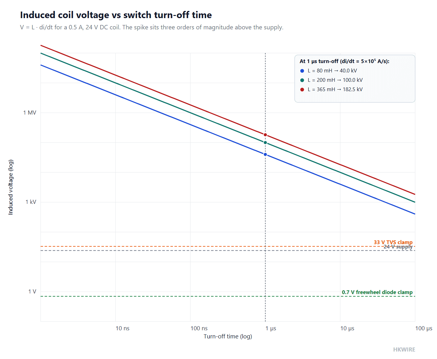
where L is the coil inductance in henries and di/dt is the rate at which the current falls at the instant of turn-off, in amperes per second. The minus sign records Lenz’s law — the induced voltage opposes the change — but for sizing the spike what matters is the magnitude L × di/dt. The faster the switch opens, the larger di/dt, and the larger the spike. A mechanical relay contact opens in microseconds; a MOSFET can switch the current off in tens of nanoseconds, which makes the spike worse, not better.
3. Worked example: 40 kV from a 24 V coil
Take a 24 V DC coil that draws 0.5 A when energized, and let the switch turn it off in 1 microsecond. The current change rate is:
di/dt = 0.5 A / 1 µs = 5 × 10⁵ A/s
The inductance depends on the coil. There is no universal standard value for a solenoid coil, so this worked example uses the figures from a specific manufacturer’s data sheet — the Hydrocom coil table linked below — and you should substitute your own coil’s value. A 24 V coil wound for series connection measures about 80 mH, while the same 24 V / 31 W coil wired for parallel connection measures about 365 mH. The numbers are far enough apart that they are worth both working through:
| Step | Expression | Result |
|---|---|---|
| Coil current at turn-off | given | 0.5 A |
| Turn-off time | given | 1 µs = 10−6 s |
| Rate of change of current | 0.5 / 10−6 | 5 × 10⁵ A/s |
| Inductance, 24 V coil, series connection | manufacturer data | 80 mH = 0.08 H |
| Induced voltage | 0.08 × 5 × 105 | 40,000 V (40 kV) |
| Inductance, 24 V / 31 W coil, parallel connection | manufacturer data | 365 mH = 0.365 H |
| Induced voltage | 0.365 × 5 × 105 | 182,500 V (182.5 kV) |
The 80 mH and 365 mH values are the series and parallel inductance of a 24 V coil from the Hydrocom coil data sheet; substitute your own coil’s figure and the method is unchanged.
Put those numbers next to the 24 V the system actually runs on. A spike of 40 kV is more than three orders of magnitude above the supply, and the parallel-wound coil reaches 182.5 kV. That is enough to puncture the drain of a driver MOSFET, arc across a relay contact, or break down the coil’s own insulation if it is marginal. The connector does not create the spike — the coil does — but the connector is the convenient place to put the component that absorbs it.
Where the suppression belongs
The spike appears across the coil, so the suppression has to be placed directly across the coil — which is exactly where a DIN 43650 valve connector puts it. Connectors in this family are routinely supplied with the suppression component mounted inside the housing, wired across the two coil terminals, so the field wiring stays two clean conductors and the protection travels with the connector. A connector without suppression is still a valid part; it just leaves the spike for the driver to survive, and most modern drivers will not survive it for long.
4. Three suppression methods, and how to pick one
Three components can sit across a coil, and they trade off clamping voltage, response speed, energy handling and whether they slow the valve down. The table below is the decision in one place; the paragraphs after it explain the one trade-off that general articles skip.
| Method | Clamp voltage | Response | Polarity | Energy | What it costs you |
|---|---|---|---|---|---|
| Freewheel diode | ≈ 0.7 V (one diode drop) | slowest — current recirculates through the diode | DC only, polarity-sensitive | low | delays valve release the most |
| TVS diode | chosen value, e.g. 33 V | nanoseconds | unidirectional or bidirectional | low energy | slightly higher clamp than a diode |
| VDR / MOV | higher, less precise | fast | bidirectional | high energy | clamp drifts as it ages |
All three clamp the turn-off spike; they differ in how much voltage they leave across the coil and how quickly the coil current can collapse.
The varistor (also called a VDR or MOV) is the bidirectional option: it works on AC and DC and absorbs more energy, which matters where the coil is switched by a mechanical contact that arcs. Its penalty is aging — every absorbed strike slightly changes the device, so the clamp voltage drifts upward over millions of operations. For a 24 V DC coil that switches frequently, the TVS is normally the better default; for an AC coil, the varistor is the only one of the three that works without a separate rectifier consideration.
There is one more decision inside the TVS choice that is worth stating out loud: the clamp voltage has to sit above the normal coil supply, so the device does not conduct during normal operation, and below what the driver can survive. For a 24 V coil a 33 V unidirectional TVS is a common choice — it stays off at 24 V, clamps the spike to about 33 V, and the driver, which only has to handle tens of volts, never sees the 40 kV the coil would otherwise produce. The exact clamp value is a design choice, but the rule is the same for every coil: clamp above the supply, below the driver’s breakdown, and let the connector carry that component.
5. Form A, Form B and Form C: the three pin spacings
With the electrical risk handled, the mechanical choice is the form. The three forms differ in pin spacing and physical size, and that spacing is the single number that must be read off the coil’s data sheet before ordering a connector.
| Form | Pin spacing | Typical contact layout | Rated voltage | Rated current | Typical use |
|---|---|---|---|---|---|
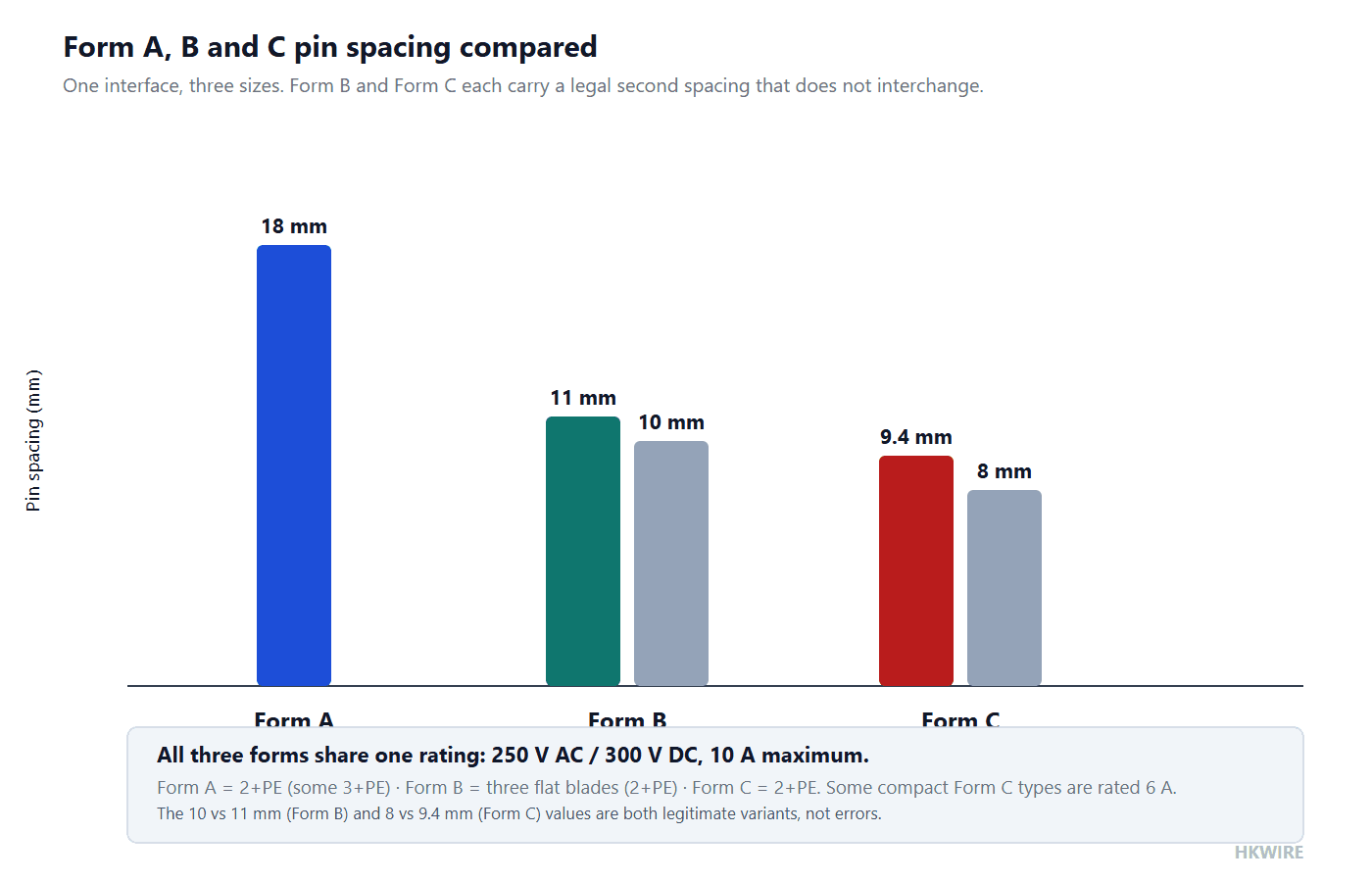
| Form A | 18 mm | 2 + PE (three positions); some 3 + PE | 250 V AC / 300 V DC | 10 A max | larger solenoids and higher-power coils |
| Form B | 10 mm or 11 mm (11 mm is the industrial standard) | three flat blade contacts (2 + PE) | 250 V AC / 300 V DC | 10 A max | the most common general-purpose valve connector |
| Form C | 8 mm or 9.4 mm (9.4 mm is the industrial standard) | 2 + PE | 250 V AC / 300 V DC | 10 A max (some types 6 A) | compact valves and smaller coils |
The 250 V AC / 300 V DC and 10 A figures are the family’s headline rating; some P1/P2 variants are rated 6 A, so confirm the specific connector against the manufacturer’s data sheet.
Form B is the workhorse: it is the one found on most general-purpose solenoid valves, with three flat blade contacts arranged as two coil terminals plus a protective-earth contact. Form A is the large option for bigger solenoids, and Form C is the compact option where space is tight. The protective-earth contact in all three is not optional decoration — it bonds the metal valve body so that a coil insulation fault trips the protective device instead of energizing the body.
6. The pin-spacing trap: close is not close enough
Form B and Form C each carry two legitimate pin-spacing values, and this is where field mistakes are made. Form B is specified as 10 mm or 11 mm, with 11 mm the industrial standard; Form C is specified as 8 mm or 9.4 mm, with 9.4 mm the industrial standard. The variants look interchangeable on a drawing because the pin count is the same and the size difference is about a millimeter — and a millimeter is exactly what decides whether the pins seat fully and make reliable contact.
A connector built for the 11 mm Form B spacing will not seat correctly on a coil with 10 mm spacing, and a forced or half-seated connection gives exactly the intermittent contact that is hardest to diagnose in the field: the valve works on the bench, then drops out under vibration or thermal cycling. The same applies to the 8 mm and 9.4 mm Form C variants. The rule is to read the coil data sheet, find the word “Form” and the spacing, and order the connector that matches both — and to write the full designation, such as “Form B, 11 mm”, into the specification rather than stopping at “Form B”.
The reason a half-seated connector is worse than no connection at all is that it passes the initial continuity check. The pins touch, the valve works on the bench, and the fault only shows up later as a contact resistance that rises with temperature and vibration. A millimeter is enough to move a blade contact from full engagement to a corner contact, and a corner contact is exactly what heats up, oxidizes and eventually opens under load — the intermittent valve failure that costs a shutdown to find.
7. Sealing, torque and the IP65 / IP67 distinction
Two different protection ratings circulate for this family, and they are achieved by two different constructions. A connector assembled correctly with its gasket against the coil achieves IP65 — dust-tight and protected against low-pressure water jets — provided the gasket is present, the screws are tightened correctly and the cable entry is sealed. A one-piece overmolded connector, where the housing is molded directly over the cable, can reach IP67, protected against temporary immersion. These are two implementations of the same idea, and they are not interchangeable claims: an IP65 gasket connector is not an IP67 overmolded connector, and writing “IP67” on a drawing for a gasketed field-wired part invites a waterproofing failure in service. The rating also covers the whole assembly, not just the gasket: the cable entry has to be sealed with a correctly sized gland or a molded entry, because a connector with a perfect gasket and a loose cable entry is still not IP65.
Torque is where the same kind of confusion shows up as damage. The tightening values for this family are manufacturer installation figures, not clauses in EN 175301-803, and more torque is not better torque. The typical figures are:
| Fastener | Typical torque (manufacturer installation guide) | What over-tightening does |
|---|---|---|
| Locking nut / knurled screw | 1.8 N·m ±10% | deforms the gasket or cracks the housing |
| Center fixing screw | 0.4 N·m ±10% | cracks the housing or over-compresses the seal |
| Contact screw (terminal) | 0.2 N·m ±10% | strips the thread or breaks the conductor |
The torque values are typical manufacturer installation figures, not an EN 175301-803 requirement; use the value printed in the connector’s own installation guide.
The center fixing screw is the one people strip, because 0.4 N·m is far below what a screwdriver-wielding hand naturally applies. The correct instinct is to treat these as small, calibrated values and to use a torque screwdriver, because the cost of over-tightening is a cracked housing that is invisible until water gets in and the coil fails months later.
8. Wiring and a selection checklist
Wiring a DIN 43650 valve connector is simple once the earth contact is respected. The two coil terminals carry the switched supply, and the protective-earth contact bonds the valve body. Polarity matters for a DC coil only if the connector carries a freewheel diode — the diode is polarity-sensitive, so a reversed DC supply leaves the diode conducting forward and the coil shorted. A TVS with a bidirectional part, or a varistor, removes the polarity concern. The earth contact must never be used as a spare conductor.
- Read the coil data sheet and record the form letter and pin spacing (for example “Form B, 11 mm”).
- Confirm the rating — 250 V AC / 300 V DC and 10 A — against the connector data sheet, since some compact types are 6 A.
- Decide the suppression: TVS for a fast 24 V DC valve, a freewheel diode only if the slower release is acceptable, a varistor for AC or high-energy mechanical switching.
- Choose the sealing honestly: IP65 for a correctly gasketed field-wired part, IP67 only for a one-piece overmolded assembly.
- Wire the earth contact to the valve body and tighten to the manufacturer’s torque, not by feel.
If the valve sits on a machine alongside sensors and network drops, the same discipline applies to those cables — our guide to M8 and M12 circular connectors covers the sensor side, and the locking choice itself is set out in our guide to connector locking mechanisms. For a connector built over the cable and sealed as one piece, see our screw-lock molded cable assemblies.
9. Five things a general guide will not tell you about a DIN 43650 valve connector
- The spike is real arithmetic, not a warning label. A 24 V coil with 80 mH switched off in 1 µs produces about 40 kV, and a parallel-wound 365 mH coil reaches 182.5 kV. That is why the suppression component exists, and why its absence usually shows up as a dead driver transistor rather than a blown valve.
- A freewheel diode slows the valve down. The lowest clamp comes with the slowest release. A fast-cycling valve needs a TVS with a chosen clamp voltage, not a diode, even though the diode is cheaper.
- Form B and Form C each have two legal spacings. 10 mm and 11 mm for Form B, 8 mm and 9.4 mm for Form C. The variants have the same pin count but do not interchange, and a half-seated connector is the intermittent fault that survives the bench and fails in service.
- Torque is not “tighten until snug”. The locking nut is about 1.8 N·m and the center screw about 0.4 N·m; going past those cracks the housing or the seal, and the failure is invisible until it is wet.
- IP65 and IP67 are two different constructions. A gasketed field-wired connector is IP65 done properly; IP67 is the overmolded one-piece build. Writing the wrong one on the drawing does not change the part, it changes who gets blamed.
How we help
Tell us the coil’s form and pin spacing, the supply voltage and how fast the valve must cycle, and HKWIRE supplies a DIN 43650 valve connector — gasketed or overmolded, with the right suppression fitted — plus the cable assembly that carries it. We are certified to ISO 9001 and return RoHS and REACH material declarations per project, so the connector you specify is the connector you can verify. See the standard build in our screw-lock molded cable assemblies, or open a project through custom development if the coil is unusual.
Frequently asked questions
What does DIN 43650 mean now that the standard is replaced?
The interface originally defined by DIN 43650 is now published as EN 175301-803, and the same family is sometimes referenced as ISO 4400. The name “DIN 43650” survives in the field because it is shorter and widely recognized, but the current document to cite is EN 175301-803, covering Form A, Form B and Form C.
How do I tell Form A, Form B and Form C apart?
By pin spacing. Form A is 18 mm, Form B is 10 mm or 11 mm (with 11 mm the industrial standard) and Form C is 8 mm or 9.4 mm (with 9.4 mm the industrial standard). The spacing is the number to read off the coil data sheet, because the plug of one form will not fit the coil of another.
Why does a 24 V valve need surge suppression?
The coil is an inductor, and at switch-off it produces a voltage of V = −L × di/dt. A 24 V coil with 80 mH of inductance switched off in 1 µs produces about 40 kV, and a 365 mH coil reaches 182.5 kV — far above the 24 V supply and enough to destroy the driver transistor or relay contact. The suppression component absorbs that spike.
Should I use a freewheel diode or a TVS diode?
It depends on valve speed. The diode clamps to about 0.7 V but keeps the coil current circulating, so the valve releases slowly. A TVS clamps to a chosen value such as 33 V in nanoseconds and lets the current collapse quickly, so a fast-cycling 24 V DC valve should normally use a TVS. Use a diode only where the slower release is acceptable.
Is the 10 A rating the same for every connector?
No. The family’s headline rating is 250 V AC / 300 V DC at 10 A maximum, but some P1/P2 and compact Form C types are rated 6 A. Always confirm the specific connector’s rating against its data sheet rather than assuming 10 A.
What is the difference between IP65 and IP67 on these connectors?
They are two constructions, not two grades of the same part. A connector assembled correctly with its gasket achieves IP65, dust-tight and protected against low-pressure water jets. A one-piece overmolded connector can reach IP67, protected against temporary immersion. Do not write IP67 onto a gasketed field-wired part.
How tight should the screws be?
Use the manufacturer’s figures, not feel. The typical installation values are about 1.8 N·m for the locking nut, 0.4 N·m for the center fixing screw and 0.2 N·m for the contact screw, each with a ±10% tolerance. Over-tightening cracks the housing or deforms the seal.
Does the protective-earth contact need to be wired?
Yes. The PE contact bonds the metal valve body so a coil insulation fault trips the protective device instead of energizing the body. It must not be used as a spare conductor, and it is the reason the three forms all include it.







