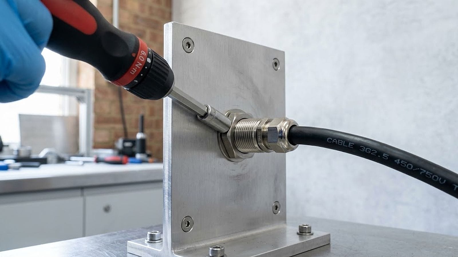
An IP67 or IP68 rating tells you a mated pair passed a one-off submersion test on a fresh, clean, room-temperature sample. It does not tell you how hard to tighten the coupling nut, what happens when the cable gets pulled sideways at a right-angle exit, or whether the seal still has any compression left after a year of thermal cycling. This article turns waterproof connector torque into a number you can put on a drawing, instead of leaving it to a field hand’s “good and tight.”
1. What an IP rating leaves out
IEC 60529 defines the test, not the installation. The IP code says a housing resisted a defined water exposure under defined conditions. The standard’s own scope quietly excludes condensation, freezing, and solar radiation, and it never once specifies a coupling torque. IPX7 is a 30-minute dunk at one meter, and IPX8 is whatever depth and duration the manufacturer negotiated with the customer. Neither one is a guarantee that your operator, on your line, torqued it the way the test lab did.
The product standard that does exist for the most common screw-lock format is IEC 61076-2-101, the detail specification for M12 screw-locking circular connectors. It defines dimensions, codings, and ratings. The installation torque you will find around it is a recommended value, not a sealing guarantee. Typical practice lands at 0.4 N·m for M8, 0.6 N·m for M12, and 1.5 N·m for the 7/8‑16 UN “mini‑change” format. Beckhoff publishes exactly these figures in its EtherCAT Box mounting instructions, and states that 0.5 N·m is the maximum permissible when tightening an M8 with its ZB8800 torque screwdriver. Other vendors publish their own figures, so treat these as indicative practice and confirm them against the data sheet for the connector you actually bought.
Over-tighten, and you crack the plastic insert or bow the panel flange. Under-tighten, and the nut walks loose under vibration. Both failure modes look identical at the customer site: water inside a connector that carries an IP rating.
An IP rating is a result you can lose at the moment of installation. The number that actually keeps the joint sealed is waterproof connector torque — and how that torque is distributed around the seal.
2. Two families of sealed joint: hard stop vs. compressible seal
Before you pick a waterproof connector torque value, figure out which family your connector belongs to, because torque does a different job in each.
- Hard-stop (metal-to-metal) joints. The coupling nut seats against a shoulder or face. Geometry and tolerance stack set the O-ring or gasket compression, not how hard you crank. Once the parts bottom out, extra torque only increases thread preload. It does not squeeze the seal any more. In this family the seal fails because the joint opens under load, not because it was under-squeezed.
- Compressible face-seal joints. The gasket itself is the stop. Here torque directly controls seal squeeze. Too little torque leaks on day one, and too much extrudes or permanently sets the gasket.
How do you tell which one you have? Assemble dry and measure, or read the mating interface drawing. If the nut comes up against a hard face with the seal compressed by a fixed shoulder, it is a hard stop. If the seal is what stops the travel, it is a compressible seal. Hard stops are common on panel-mount connectors that clamp through a bulkhead, so check the flange detail before you budget any torque at all.
Everything below assumes a compressible face seal, because that is the case where the waterproof connector torque is yours to choose. The prying math in Section 5 applies to both families.
3. The waterproof connector torque budget: one formula
Machine design has a single, textbook relation between tightening torque and the axial clamp it produces:
F = T / (K · D)
T in N·m · D in m · F in N
Here T is the applied torque, D is the nominal thread diameter, K is the nut factor, and F is the axial preload. Spread that preload over the seal’s contact circumference, then add the off-center load from a side pull at a right-angle exit. You get the one equation this whole article rests on:
q = F / (π · dg) ± 4 · W · h / (π · dg²)
dg and h in mm · W in N · q in N/mm
The result q is the sealing line load in newtons per millimeter of seal contact circumference. Throughout this article dg and h are in millimeters, so q comes out in N/mm. If you work in SI throughout, multiply by 1000 to get N/m. The symbols:
dg— the mean contact diameter of the seal (mm). For an O-ring it is the ring’s centroid diameter. Read it off your drawing; do not guess.W— the side pull on the cable at the exit (N).h— the perpendicular distance from the seal plane to the cable centerline, which is the “lever arm” of a right-angle exit (mm).
The plus term is the tight side of the seal. The minus term is the loose side. The seal only does its job while the loose side stays positive. When the second term grows until the minus side reaches zero, one side of the gasket has lost all its compression. That is where leakage and fretting begin, even though the nut has not budged.
One formula, two physical effects. The first term is the waterproof connector torque you chose. The second is the side load your layout created. Keep them separate on the drawing, and in your head.
One caveat on K. A value near 0.2 is a rule of thumb for a dry, plain, unlubricated thread. Real nut factors run roughly from 0.15 to 0.25, and lubrication or a different plating can push them lower still, so the same torque can produce substantially different preload. Treat F as an estimate with wide error bars, not a precision result.
4. Worked example: M8, M12, and 7/8-16 UN at rated torque
Run the waterproof connector torque budget for the three common screw-lock sizes at their typical installation torques:
| Coupling | Torque T (N·m) | Preload F (N) | Seal dia dg (mm) | Line load q (N/mm) | Side pull to open seal (kgf) |
|---|---|---|---|---|---|
| M8 × 1 | 0.4 | 250 | 6 | 13.3 | 2.6 (h = 15 mm) |
| M12 × 1 | 0.6 | 250 | 10 | 8.0 | 3.2 (h = 20 mm) |
| 7/8-16 UN | 1.5 | 338 | 20 | 5.4 | 4.9 (h = 35 mm) |
Two things jump out. First, M8 and M12 produce the same 250 N of preload. Manufacturers scale torque roughly with diameter, so the ratio T/D stays about constant, and the clamp force lands in the same place. Second, and this is the counter-intuitive one: the 7/8-16 UN coupling carries 1.5 N·m and 35% more preload than the M12, yet its sealing line load is lower (5.4 vs. 8.0 N/mm). The bigger the connector, the longer the seal’s circumference, so the same — or even a larger — clamp force gets spread thinner.
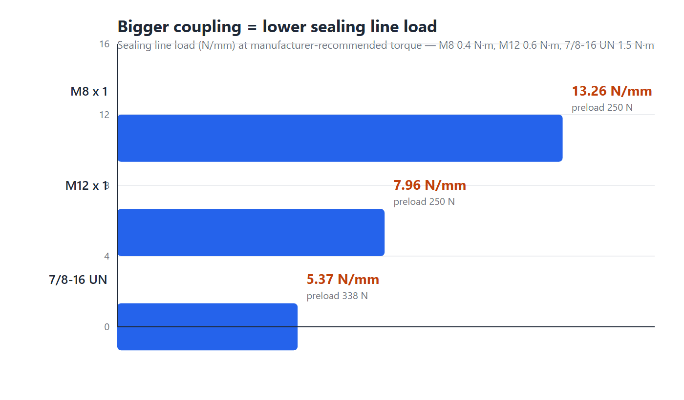
The practical consequence: if your gasket needs a certain compression per millimeter to seal, a bigger connector does not automatically give you more of it. When a large-format connector leaks, “put a bigger connector on it” is often exactly the wrong fix, because a larger shell buys you less line load, not more.
The M8 row is not hypothetical. It is the size covered by IEC 61076-2-104, the detail specification for circular connectors with M8 screw-locking, and it is the size our M8 screw-lock cable assemblies are built around. You can browse the whole M8 and M12 range, or the 7/8-inch power cables for the large-format case.
5. The right-angle exit turns side pull into a lever
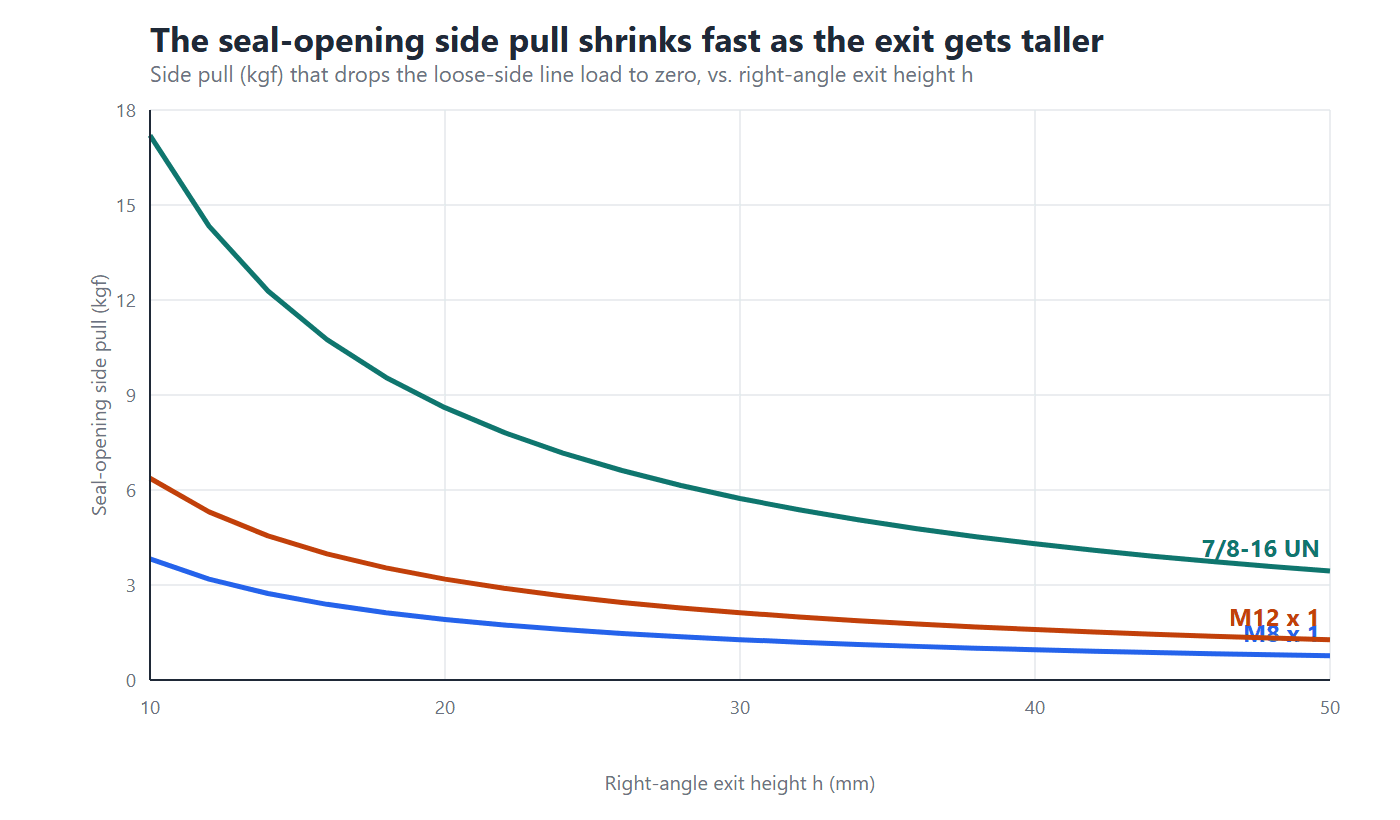
Now add the second term, which is the part of the waterproof connector torque budget most people forget. On a right-angle connector, the cable runs parallel to the panel, at a height h above the seal plane. A pull along the cable is therefore a side pull, and it creates a prying moment M = W · h about the seal. On a straight exit the cable is coaxial, so axial tension produces no such lever. The same load simply pulls along the thread axis, and the preload resists it directly.
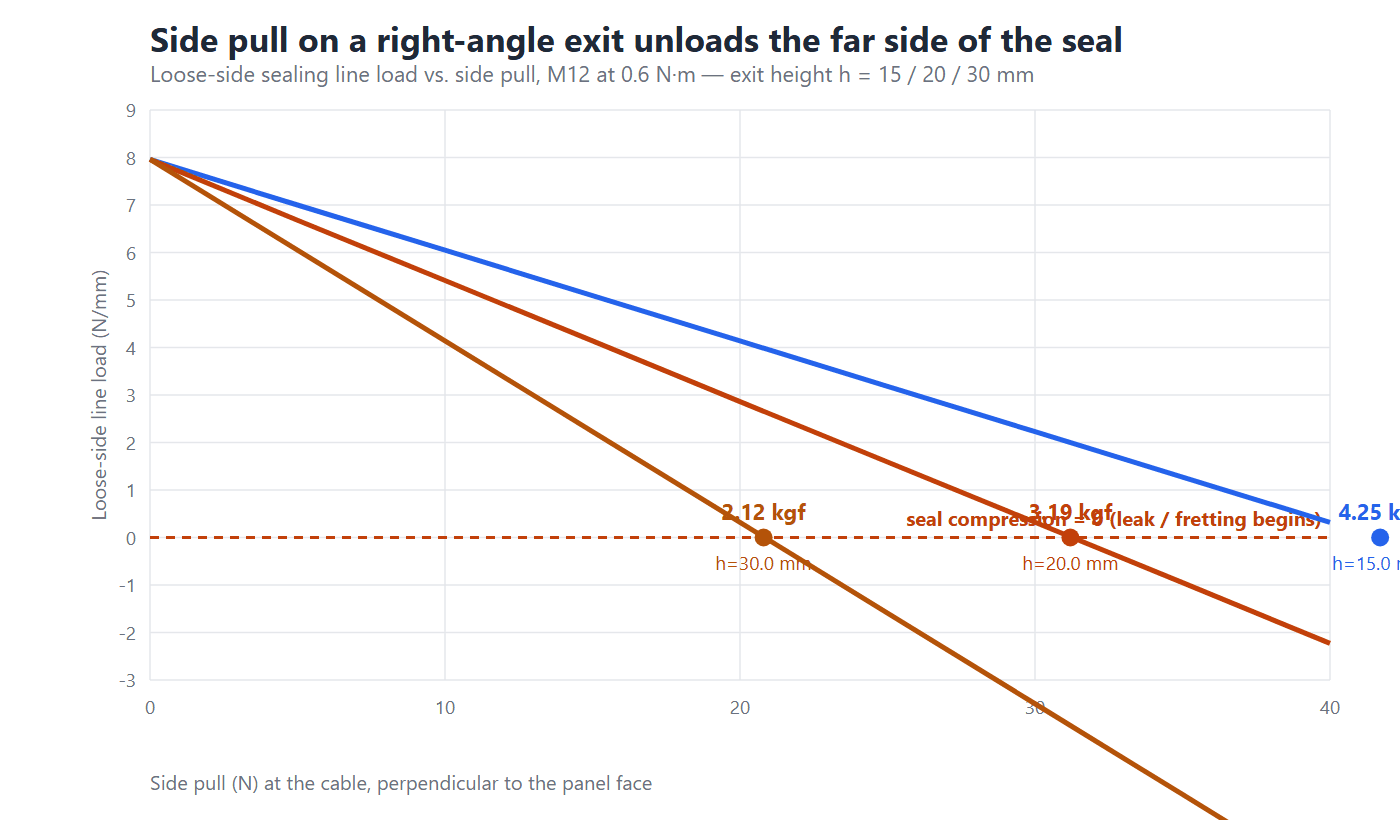
For an M12 at 0.6 N·m, the side pull that zeroes out the loose side of the seal is small. It gets smaller as the exit gets taller:
| Right-angle exit height h | Side pull that opens the loose side |
|---|---|
| 15 mm | 42 N (4.3 kgf) |
| 20 mm | 31 N (3.2 kgf) |
| 30 mm | 21 N (2.1 kgf) |
Read that carefully. At a typical 20 mm right-angle exit, a side pull of barely three kilograms is enough to drop one side of the seal to zero clamp. That happens long before the coupling nut shows any sign of loosening. So a “sealed” right-angle cable can pass its bench IP test and still leak in service, because the test stand pulls nothing sideways.
The fixes are all about shrinking h, or removing the load before it reaches the seal plane. Choose the lowest-profile exit that still clears your cable’s bend radius. Clamp the cable to a fixed structure within the first few centimeters. Then put the strain relief — ideally a molded strain relief — in series with the seal, so the overmold carries the pull and the connector only carries the seal. Where a right-angle exit is unavoidable, our right-angle M12 D-code, right-angle M8, and right-angle M12 L-code power assemblies are built with that lever arm as an input to the waterproof connector torque budget, not an afterthought.
6. Where installations lose the waterproof connector torque you specified
A drawing that names a waterproof connector torque of 0.6 N·m does not guarantee that 0.6 N·m still acts on the seal by the time the machine ships. In practice, six field situations eat the waterproof connector torque you specified. Every one of them is cheap to prevent and expensive to diagnose later.
| Installation situation | What it does to the joint | What to specify or do |
|---|---|---|
| Cable installed with a twist | The cable acts as a torsion spring. It unwinds against the coupling nut, so a joint that read 0.6 N·m on the bench is loose by the next shift. | Straighten the cable before mating. Hold the connector body with a second wrench while tightening, so the cable cannot drag the nut back. |
| Thin or unsupported panel | The flange bows as you tighten. The seal face goes wedge-shaped, and one side never reaches its compression window. | Add a backing plate or reinforcing washer, and hold the panel thickness and cutout to the vendor’s drawing. This is the usual root cause with bulkhead and panel connectors. |
| No strain relief near the exit | Cable weight, routing tension, and vibration all arrive as side pull, which is the prying term from Section 5. | Clamp the cable within the first few centimeters. Route it so the load path never runs through the seal plane. See our notes on bend radius, pull force, and routing. |
| The wrench will not fit | With connectors packed side by side, or inside a cabinet, the operator can only hand-tighten, and the value lands well below spec. | Leave wrench clearance in the layout, or change the hardware: a right-angle exit, or a push-pull quick-lock format that needs no tool at all. |
| Seal not seated | A twisted, missing, or displaced O-ring turns a face seal into a point contact, so the real dg is not the one you budgeted. | Inspect the seal before mating. Start the thread by hand; if resistance feels uneven or the nut never takes up progressively, back off and re-seat it. |
| Thread friction has changed | Lubrication, plating, stainless-on-stainless galling, and wear from repeated mating all move K, so the same torque gives a different preload. | Do not lubricate unless the vendor allows it. Re-check K whenever the plating or material changes, and watch for galling on stainless couplings. |
A four-step sequence that survives an audit
The order matters as much as the waterproof connector torque value. This is the sequence we recommend on a build sheet:
- Align the coding, then start by hand. Match the keyway and the coding first — see our M12 coding guide if the letters are unfamiliar. Run the nut down with your fingers until the faces meet. If it binds or cross-threads, stop: a wrench will only turn a small problem into a scrapped connector.
- Dress the cable. Remove any twist, and make sure no tension is being carried into the plug while you tighten.
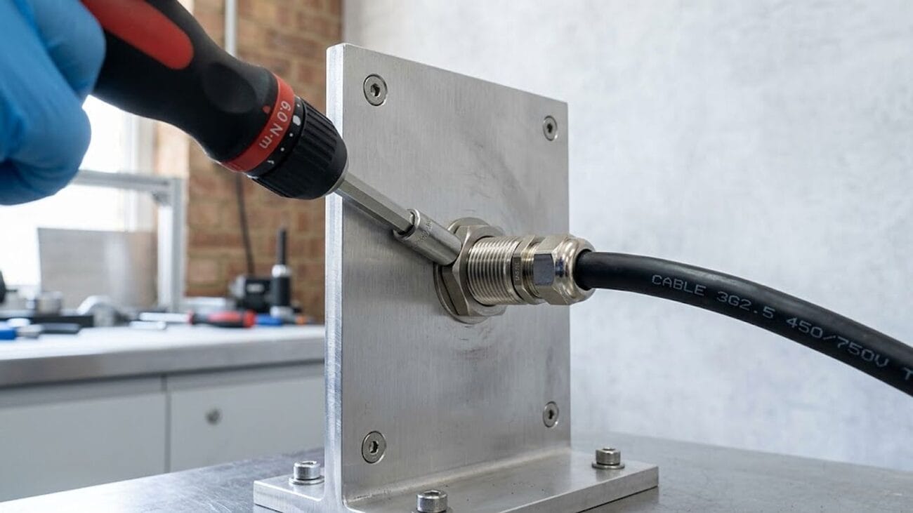
- Torque to value, holding the body. Use a preset wrench or torque screwdriver. Hold the connector body steady so the cable does not rotate with the nut.
- Mark it and record it. Put a witness mark across the nut and the body, and log the value. The mark makes a later visual check trivial, and it is the cheapest way to catch a joint that has backed off.
What if the line has no torque wrench?
It happens, especially on small couplings where a wrench feels like overkill. The workaround is to calibrate the job rather than the hand. On a first article, tighten with a torque wrench to the specified waterproof connector torque, then measure what that looks like in terms an operator can repeat: how far past finger-tight the mark travels, or the angle from first contact to final position. Write that turn angle or witness-mark position into the work instruction, then spot-check with a torque wrench at the start of each shift.
Two practical notes. A torque screwdriver is usually the better tool below about 2 N·m, because a general-purpose wrench loses accuracy at the bottom of its range. And whichever tool you choose, calibrate it on the interval the tool maker specifies — a wrench that has drifted is worse than no wrench, because it gives you false confidence.
7. Why the water is the easy part
Here is the result that surprises most people who ask “how much waterproof connector torque do I need?”: the water barely needs any. Treat the rating as an internal pressure trying to pry the joint apart, which is the worst case for a face seal, and the required line load is qp = P · dg / 4:
| Depth (rating) | Pressure | Required line load (M12) | vs. the 8 N/mm available |
|---|---|---|---|
| 1 m (IPX7) | 0.098 bar | 0.02 N/mm | ≈ 325× margin |
| 10 m (IP68) | 0.98 bar | 0.25 N/mm | ≈ 32× margin |
And that is the generous framing. In a real submersion the external pressure pushes the plug into the socket and compresses the joint, so it does not pry it apart. Waterproof connector torque is therefore not what holds the water back. Its real jobs are, first, keeping the joint mechanically closed against vibration and side pull so the seal stays seated, and second, holding the gasket inside its intended compression window. Lose torque and you lose both. The water just takes advantage of the opening.
Stress relaxation and the re-torque habit
Even a correctly torqued seal does not stay that way forever. Elastomer gaskets and O-rings undergo stress relaxation: the compression force decays over hours to weeks, and faster at temperature. A joint that was marginal on day one can be under-squeezed by week two. The cheap, standard remedy is a re-torque after the first thermal cycle. Bring the coupling back to spec once the gasket has taken its set.
Vibration is the second enemy
Vibration attacks a threaded coupling the same way it attacks any bolt. The preload from a correctly torqued nut is what resists self-loosening. Once the clamp force drops, micro-motion starts, and both the seal and the contacts degrade. Where vibration is the dominant load, the locking mechanism matters as much as the torque — see our comparison of bayonet, push-pull, and threaded retention.
Test it the way the field will use it
Finally, an IP certificate is earned on a fresh, dry, room-temperature sample. The honest sequence runs the environmental cycling first — thermal shock, damp heat, UV, and salt spray if it is coastal — and then the IPX7/IPX8 dunk, followed by a 100% electrical test. We cover the sequence, and the four seals inside every waterproof cable assembly, in more detail there.
8. Seal compression windows: how much squeeze each material can take
Section 7 said the torque’s second job is holding the gasket inside its intended compression window. That window deserves its own numbers, because it is where many seal designs quietly fail. Squeeze too little and the material never fills the micro-texture of the mating surfaces, so water gets a leak path. Squeeze too much and the elastomer takes a permanent set, loses its resilience, and stops sealing the next time the joint is opened. The working window sits between the two, and it depends on the material.
| Seal material | Static seal (typical) | Dynamic seal (typical) | Absolute maximum |
|---|---|---|---|
| Silicone | 20–30% | 10–15% | ≈35–40% (tears easily) |
| EPDM | 15–25% | 10–15% | ≈30% |
| NBR | 15–25% | 10–15% | ≈30% |
These are typical industry design windows for static face and radial seals. Treat them as a starting point, and confirm the working window against the specific seal supplier’s datasheet before the value goes on a drawing.
What each material is good at
Silicone keeps its resilience across the widest temperature range, which is why it dominates outdoor and high-temperature connector seals. It is also soft, has high friction, and tears easily, so it is a poor choice for joints that are mated and un-mated frequently. Its thermal expansion is unusually large: in an application with wide temperature swings the groove must keep enough void volume for the compound to expand into, or thermal growth alone can fill the groove and destroy the seal.
EPDM resists weathering, ozone, and water vapor better than almost any other common elastomer, which suits outdoor panels and washdown equipment. It is also the material behind most sponge seals: foamed EPDM runs at much larger compression, typically 30–50%, to give a soft closing force on doors and enclosures. Connector face seals stay solid and use the static window in the table above.
NBR is the workhorse O-ring of general industry and the default choice wherever oil or fuel is present. In dynamic duty its compression is deliberately kept at the low end, because over-squeezing multiplies running friction, and friction heat is what ages the compound fastest.
Cross-section and hardness move the window
Two second-order effects adjust the percentages above. First, seal cross-section: a thicker seal cord tolerates a lower squeeze. O-rings of roughly 5.33 mm cross-section and above seal well near 15%, while thin cords below about 1.78 mm usually need the high end of the static window, 25–30%, to close their relatively larger gap tolerances. Second, hardness: 70 Shore A is the standard reference compound, so a harder 90 Shore A seal should be compressed less, and a soft 50 Shore A seal more.
Folding it into the waterproof connector torque budget
The specification sequence runs material, then geometry, then torque. Pick the seal material and its window, check the groove and mating gap against that window, compute the line load the joint actually delivers from Section 3, and only then set the installation torque. If the delivered squeeze lands outside the window, the fix is geometry — a different groove depth or seal section — not a bigger torque value, because torque that over-squeezes the seal is what kills it in the first place. On our overmolded industrial cable assemblies the seal geometry is fixed at the mold, so the compression window is locked in before the first unit ships.
9. What to write on the drawing: a waterproof connector torque checklist
Boil this down to a checklist. These eight lines turn an IP rating into a waterproof connector torque you can actually enforce. A screw-lock connection is fully specified only when the drawing names:
- Coupling torque in N·m, plus the tool and method (preset torque wrench or torque screwdriver, not “hand-tight”).
- The seal family — hard stop or compressible face seal.
- The seal geometry you budgeted with —
dgand the exit lever armh. - A maximum side-pull limit (N) at the exit, not just an IP rating.
- Gasket material and compression window — Section 8 gives typical windows; the supplier’s datasheet governs.
- Re-torque instruction after the first thermal cycle.
- Assembly constraints — panel thickness, backing plate, wrench clearance, and strain-relief distance.
- The environmental sequence the assembly must survive before its IP test.
Most RFQs we receive specify the IP rating and stop there. That is the part the rating already guarantees on paper. The waterproof connector torque, the side-pull limit, the assembly constraints, and the re-torque habit are the parts that decide whether the rating survives contact with the real machine. For a full list of what else belongs on the drawing, see our wire harness drawing checklist, and for the commercial side, how to prepare a custom cable assembly RFQ.
Frequently asked questions
What waterproof connector torque should I use for an M12 connector?
0.6 N·m is the widely used installation value for IP67 M12 screw-locking connectors, and it is what Beckhoff specifies in its EtherCAT Box mounting instructions. The governing detail specification is IEC 61076-2-101, which does not itself fix an installation torque. Below the manufacturer’s value the nut can walk loose under vibration; above it you risk cracking the insert or distorting the flange. Always confirm against the vendor’s data sheet for the exact part you are holding.
What about an M8 connector?
0.4 N·m is the commonly published value, again from Beckhoff’s EtherCAT Box instructions, which also state 0.5 N·m as the maximum permissible when tightening with the ZB8800 torque screwdriver. The M8 format is covered by IEC 61076-2-104. Because M8 parts are small and easily overtightened, a torque screwdriver is a better choice than a wrench.
Does a higher IP rating need more waterproof connector torque?
No. The hydrostatic load at IP68 depths is a few tenths of a newton per millimeter, which is orders of magnitude below the clamp the torque already provides. Torque is for mechanical retention and for holding the gasket in its compression window, not for resisting water pressure.
Why does my 7/8 connector leak when my M12 does not?
Usually because the larger format spreads its preload around a much longer seal circumference, so the line load is actually lower. Check whether it is a hard-stop or compressible-seal design, confirm the recommended torque is being reached with a wrench, and rule out side pull at a long exit.
Does a right-angle connector seal worse than a straight one?
Not inherently, because the seal itself is the same. But a right-angle exit gives any side pull a lever arm that a straight exit does not have. Manage the exit height and the strain relief, and it seals just as well.
Should I re-torque after installation?
Yes, after the first thermal cycle. Elastomer stress relaxation reduces the clamp over the first hours to weeks, so bringing the coupling back to spec after the gasket takes its set is the cheapest reliability improvement you can make.
Is “hand-tight” good enough?
No. Hand tightening is not reproducible between operators, and it routinely lands below the recommended value on small couplings. Use a preset torque wrench or a torque screwdriver for anything that carries an IP rating. If no wrench is available on the line, calibrate a turn angle or witness-mark position from a first article and write it into the work instruction.
Should I lubricate the coupling thread?
Only if the connector vendor explicitly permits it. Lubrication lowers the nut factor, so the same torque produces a much higher preload, and you can overload the insert or the flange without ever exceeding the specified torque. The same applies to any change in plating or coupling material, since both move the friction coefficient.
Does un-mating and re-mating change the torque?
The specified torque does not change, but the joint does. Repeated mating wears the thread and work-hardens the seal, and a gasket that has taken a compression set will not spring back to its original squeeze. On serviceable joints, inspect the seal each time it is opened, and re-torque to the same value rather than to the same nut position.
Does coupling torque affect the electrical contact?
Indirectly. Contact resistance is set by the contact spring force and the plating, not the coupling torque — see our gold vs. tin plating article. But if a loose coupling lets the joint micro-move, the contacts fret and resistance climbs over time.
How much should the seal be compressed in a waterproof connector?
For a static seal, typical design windows are 20–30% squeeze for silicone and 15–25% for EPDM or NBR. Dynamic duty drops to 10–15% to limit friction and wear. Thin seal cords run at the high end of the window and harder compounds at the low end. Treat these as typical industry windows and confirm the working value against the seal supplier’s datasheet.
Need the torque spec locked down before tooling?
HKWIRE — screw-lock molded cable assemblies, specified to torque. At HKWIRE, we build M8, M12, and 7/8‑16 UN assemblies with the seal geometry, strain relief, and side-pull limit defined on the drawing, not left to the installer. Send us your interface and operating environment, and we will return a specification, not a guess.
At HKWIRE, we treat waterproof connector torque as an engineering specification, not a hand feel, because a rating is only ever as good as the last installation that touched it.
Torque values (M8 0.4 N·m, M12 0.6 N·m, 7/8‑16 UN 1.5 N·m, and the 0.5 N·m M8 maximum for the Beckhoff ZB8800 torque screwdriver) follow Beckhoff’s published EtherCAT Box mounting instructions and are indicative installation practice; other vendors publish different values, so confirm against your connector vendor’s data sheet. The nut factor K ≈ 0.2 is a rule of thumb for dry, plain threads; real values vary with lubrication, plating, and material. Nominal thread diameter is used as an engineering approximation in place of the pitch diameter. Seal compression windows in Section 8 are typical industry design values for static face and radial seals and must be confirmed against the specific seal supplier’s datasheet. Standards referenced: IEC 60529, IEC 61076-2-101, and IEC 61076-2-104.