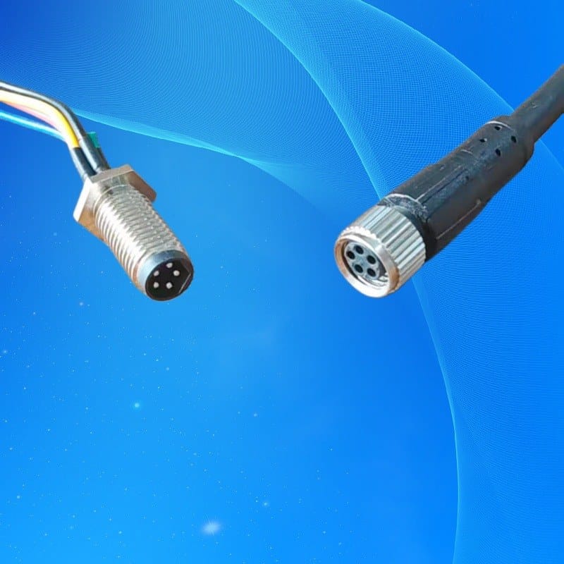
M8 6-Pin Screw-Lock Cable
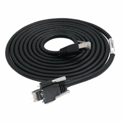
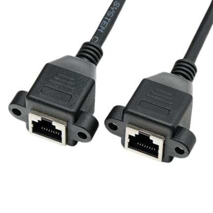
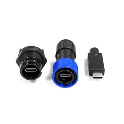
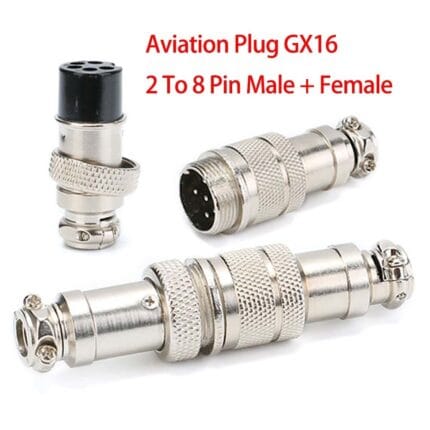
This m8 screw lock cable puts a flanged, panel-mount M8 male with threaded locking on one end and a molded A-coded female on the other, giving sensor wiring a rigid anchor point where vibration would loosen a plain snap-in fit.
Overview
This m8 screw lock cable puts a flanged, panel-mount M8 male with threaded locking on one end and a molded A-coded female on the other, giving sensor wiring a rigid anchor point where vibration would loosen a plain snap-in fit.
The flanged male body drops through a standard panel cutout and locks with its threaded nut, so the connection point no longer depends on the sensor’s own threaded neck to carry mechanical load. That separation is what makes this screw lock arrangement useful on vibrating machines: the cordset is anchored to the panel, and the sensor simply mates to it.
Key Specifications
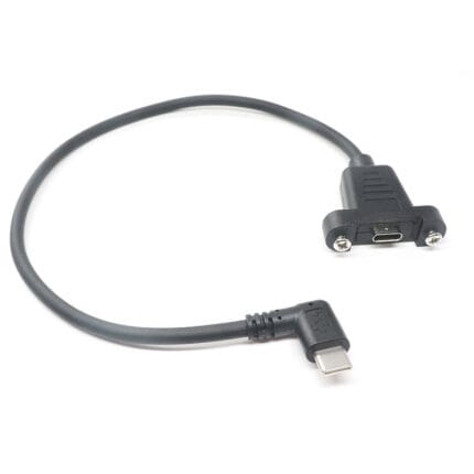
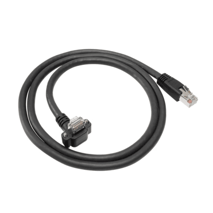
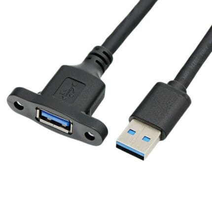
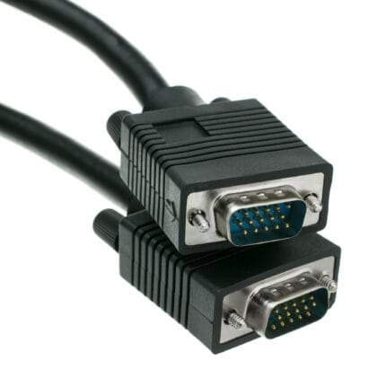
The table below lists the configuration shown in the product photo.
What the Flange Actually Solves
A pigtail-style sensor has its connector built into the device body. Every time someone pulls the cable, twists it during installation, or lets the drop hang unsupported, that load travels into the sensor’s own neck, and eventually into the potting inside it. A failed sensor in these conditions often has nothing electrically wrong with it — the sensing element still works and the leads have simply been worked loose.
A flanged panel-mount half breaks that load path. The connector is bolted to the panel, so strain from the cable side is taken by the panel, and the sensor only has to make its own electrical contact. On any machine that shakes — vibratory feeders, presses, packaging lines, screening equipment — this is the difference between a sensor that lasts and one that becomes a recurring spare part.
Panel Cutout and Thread Notes
The flange seats against the outside face of the panel and is retained by a threaded nut from the rear, so the hardware clamps the panel between two surfaces rather than relying on thread engagement alone. Panel thickness matters: too thick and the nut will not reach the thread; too thin and the assembly lacks the stiffness it needs.
Tell us the panel material and thickness when you inquire. It is a small detail that decides whether the fitting is rigid or merely present, and it cannot be corrected after the fact without changing the hardware.
Two directions of assembly exist across the industry. A front-mounted body drops in from outside the enclosure and is secured from the back; a rear-mounted body is pushed through from inside. Check which suits your access: once a cabinet is populated, many panel openings are reachable from one side only.
Construction and Materials
On the pigtail side the male contacts exit to individual color-coded cores with an overall shield braid, ready for termination inside the control enclosure or onto a customer terminal block. The opposite end is a fully overmolded female connector whose potting seals the contact area and cable entry against dust and fluid splash. The metal coupling nuts are knurled for grip with gloved hands.
The panel side is a flanged body with a threaded nut, so the load path goes into the panel rather than into the sensor neck, and the pigtail side leaves the cores color-coded and screened for termination inside the enclosure. The female end is overmolded and potted.
The screen deserves a decision at install time. It should land where your cabinet’s grounding scheme specifies, and the drain should be kept short. A screen left floating at the enclosure end protects nothing.
Typical Applications
Use it as the fixed interface for proximity switches on vibrating feeders, sensor drops on press machines, actuator feedback on packaging equipment, or any M8 device mounted where routine connector unplugging would otherwise stress the sensor thread. It is also a clean way to bring an M8 field connection to the wall of a small junction box.
Vibratory equipment is the strongest case. Feeder bowls and screens run continuously in resonance, and any connector not anchored to structure will eventually work loose regardless of how carefully it was tightened.
Press machines and forming equipment add shock loads to the problem. Each cycle sends an impulse through every connection on the frame, and those impulses add up over millions of strokes.
Junction boxes take the third case: where several sensors must reach a sealed enclosure, individual panel-mounted connectors are tidier and more serviceable than a bundle of cables through glands.
Compatibility and Fitment
The A-coded keyway follows IEC 61076-2-104 and mates with standard M8 sensor connectors. The six-position A-coded contact layout supports multi-conductor sensor and actuator circuits on a single standard panel cutout. Share your device pinout with the order and we will wire the pigtail to match it.
For higher-density circuits, or where the device itself is larger, the same concept is available in M12 and M16 form; the principle of anchoring the interface to the panel carries across.
Vibration, Strain Relief and Service Life
Anchoring the connector is only half the job. The remaining strain either side of the panel still has to be managed: clip the internal cores so nothing hangs off the contacts, and support the external cable within a short distance of the flange so the first thing taking the weight is not the join.
For serviceability, this arrangement is worth specifying for another reason. When a sensor is replaced, the expensive part is the labor and the downtime, not the device. Unplugging a failed unit from a fixed panel connector takes seconds and cannot damage the wiring that stays in place.
Custom Builds and Ordering
Pigtail length, core count, shield termination style and connector gender combinations are built to order. Send the schematic page and panel thickness and we will quote the matching assembly. Prototype and sample lots run from 1 to 50 pieces and ship in 3 working days; production orders start at 500 pieces per part number and ship 14 working days after approval, with new overmold tooling adding about 10 working days.
Packaging and Shipping
Assemblies ship with a protective cap over the male contacts, individually bagged and labeled.
Quality and Compliance
Each unit is continuity tested across all contacts and the shield, and the overmold is inspected for complete fill. See the IEC 61076-2-104 M8 connector standard for the governing interface specification.
Frequently Asked Questions
Does the panel hardware come with the cordset? It can. Request it with the order and we will include the matching nut.
Do I need to tell you the panel thickness? Yes. It determines the correct hardware and how rigidly the flange seats.
Which way does it mount? Front or rear mounting is available; choose based on the access you will have.
Can the pigtail be wired to our own pinout? Yes. Send the pin assignment and we will terminate to it.
Related Cable Ranges
Browse the related ranges: Screw-Lock Molded Cable Circular M-Series Cable Assemblies Signal and Data Cables.
Compare the cordset-to-cordset version in the IP67 right-angle M8 sensor cable, and the larger family member in the M12 A-code sensor cable.
| Connector A | M8 male, 6-position, flanged front-panel mount with locknut |
|---|---|
| Connector B | M8 female, 6-position, A-coded, overmolded |
| Coding | A-coded per IEC 61076-2-104 |
| Pigtail Cores | Color-coded conductors with overall shield (as shown) |
| Application | Sensors and I/O on vibrating equipment |
| Mounting | Panel hole with threaded locknut |
| Contacts | 6-pin |