

Most buying guides turn shielded vs unshielded cable into a quality ladder: shielded at the top, unshielded for people who have not met a VFD yet. That model is wrong in a way that costs money. A shield is not a wall around the signal; it is the return path the interfering current must be given a low-impedance way home through. Bring that current home through a 50 mm drain wire and you have inserted a 43 nH inductor in series with your own protection. This comparison of shielded vs unshielded cable works only from numbers: transfer impedance, the impedance of the shield return path, and the balance your cable loses either way.
1. Shielded vs Unshielded Cable: the Number That Decides It
Shielded cable performance is not described by coverage or by the word “industrial”. It is described by transfer impedance, written Z_T and quoted in mΩ per meter: the voltage that a given shield current couples onto the inner conductor, per unit length, per unit of that current. Lower is better, and because it is an impedance rather than a percentage, the differences between products are factors, not fractions.
Two details matter when reading a datasheet. First, Z_T covers resistive and inductive coupling only; the electric-field path is transfer admittance and is rarely what limits a drive or a PROFINET segment. Second, it is measured, not calculated — the triaxial method of IEC 62153-4-3, with line injection as the alternative in IEC 62153-4-4 — and two cables of identical construction can differ by a factor of five once the drain wire and the connectors are added.
An unshielded cable has no Z_T; nobody measures a number that does not exist. Its equivalent figure is pair balance, published as TCL and EL TCTL, which is why ISO/IEC 11801 specifies balance for unshielded cabling and shielding parameters for it not at all, as the Draka screening and balance white paper sets out. The honest first question in any shielded vs unshielded cable comparison is therefore not which is better, but which coupling path dominates.
2. The Pigtail Is an Inductor in Series, Not a Resistor to Ground
Most drawings show the shield as a conductor tied to earth, and it reads like a shunt: noise arrives, noise goes to ground, done. In reality the shield current travels from the field, along the shield, through the termination and back into the reference system. Every millimeter of that termination is an inductor, and all of it sits in series with the current you are trying to divert.
The inductance of a straight round wire is given by one expression, used for every number in this article:
L(nH) = 0.2 · l · [ ln(4l/d) − 1 ]l = wire length (mm), d = wire diameter (mm); valid for l > 100 d with μr = 1. At DC and low frequency, replace the bracket with −0.75.
Put a realistic pigtail into it: a 1 mm drain wire, 50 mm long, which is what a technician leaves after folding the shield back, twisting it and crimping on a ring terminal:
L = 0.2 × 50 × [ ln(200) − 1 ] = 10 × (5.298 − 1) ≈ 43 nH
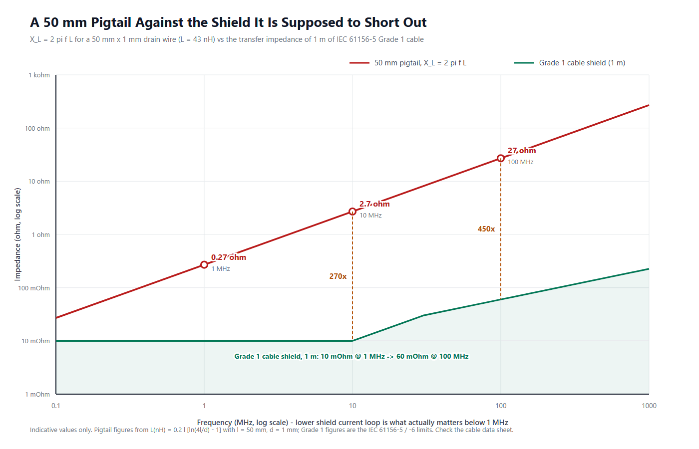
The rule of thumb of 1 nH per mm gives 50 nH, the same order of magnitude. The next step is X_L = 2πfL, that same expression evaluated at a frequency: 0.27 Ω at 1 MHz, 2.7 Ω at 10 MHz, 27 Ω at 100 MHz. Set it against the shield it is supposed to extend, using the Grade 1 limits of the next section.
| Frequency | X_L of the 50 mm pigtail (43 nH) | Grade 1 cable shield, 1 m | Ratio |
|---|---|---|---|
| 1 MHz | 0.27 Ω | 10 mΩ | 27× |
| 10 MHz | 2.7 Ω | 10 mΩ | 270× |
| 100 MHz | 27 Ω | 60 mΩ | 450× |
At 10 MHz the termination is already two orders of magnitude worse than the shield it terminates, and 12 m of braid cannot compensate for it. The bottleneck is not the cable.
3. Shielded vs Unshielded Cable: What the Grade Limits Buy
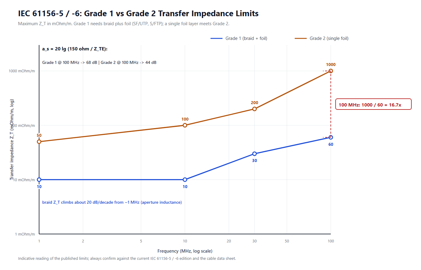
Cable standards do not say “shielded” or “not shielded”. IEC 61156-5 and IEC 61156-6 publish transfer impedance limits by grade, and the grades separate by construction, not by marketing. Grade 1 requires braid plus foil (SF/UTP, S/FTP); a single foil layer is enough for Grade 2.
| Frequency | Grade 1 (braid + foil) | Grade 2 (single foil) | Grade 2 / Grade 1 |
|---|---|---|---|
| 1 MHz | 10 mΩ/m | 50 mΩ/m | 5× |
| 10 MHz | 10 mΩ/m | 100 mΩ/m | 10× |
| 30 MHz | 30 mΩ/m | 200 mΩ/m | 6.7× |
| 100 MHz | 60 mΩ/m | 1000 mΩ/m | 16.7× |
Two shapes are worth memorizing. A braid shield is not flat: from roughly 1 MHz its Z_T climbs at about 20 dB per decade, because coupling becomes aperture-inductance dominated once the braid openings are no longer small compared with the wavelength. Shielding gets worse as frequency rises — the opposite of what most people assume. And the Grade 1 to Grade 2 gap is not constant: 5× at 1 MHz, 16.7× at 100 MHz.
3.1 Turning transfer impedance into shielding attenuation
System budgets are written in decibels, so the impedance must be converted. For an electrically short device, a_s = 20 · lg ( 150 Ω / Z_TE ), where 150 Ω is the standardized impedance of the measuring circuit, as defined in IEC 62153-4-15. Connectors use 50 Ω in the same expression (IEC 62153-4-10); electrically long devices use a power ratio.
| Frequency | Grade 1 a_s | Grade 2 a_s | Gap |
|---|---|---|---|
| 1 MHz | 83.5 dB | 69.5 dB | 14.0 dB |
| 10 MHz | 83.5 dB | 63.5 dB | 20.0 dB |
| 30 MHz | 74.0 dB | 57.5 dB | 16.5 dB |
| 100 MHz | 68.0 dB | 43.5 dB | 24.5 dB |
At 100 MHz the braid buys 24.5 dB over a single foil. With 6 dB of EMC margin you may not need it; failing by 20 dB, no amount of drain-wire craftsmanship will save a Grade 2 part, and a Grade 1 cable will — at the cost of diameter, stiffness and price. The site guide to Cat5e vs Cat6 vs Cat6a covers the same trade in the Category framework.
4. Four Calculations Generic Guides Leave Out
4.1 How long may the pigtail actually be?
“Keep the pigtail short” is not a specification. The reverse calculation turns it into one, starting from the noise budget you already have. Suppose the shield may carry up to 5 mA and the common-mode voltage on the reference plane may not exceed 100 mV — a return-path impedance of 100 mV / 5 mA = 20 Ω. Solving the same inductance expression for the length that produces 20 Ω at each frequency gives the allowed pigtail length.
| Frequency | Allowed inductance | Allowed pigtail length | What it means on the bench |
|---|---|---|---|
| 1 MHz | 3183 nH | about 1990 mm | any pigtail you can physically make |
| 10 MHz | 318 nH | about 267 mm | still generous |
| 100 MHz | 32 nH | about 39 mm | shorter than a typical folded-back pigtail |
Run it the other way and a 50 mm pigtail consumes the whole budget at 74 MHz. Below that it is survivable; above it, it is the dominant coupling path in the assembly. “Short” is a frequency-dependent number, not a length. Tighten the budget to 10 mV and every length in the table divides by ten — the quantitative reason a shield must reach the enclosure through the connector shell, not through a wire.
4.2 Series, not shunt: the shield looks like an open circuit at 100 MHz
Read Section 2 as a circuit, not a table. The 50 mm pigtail is 27 Ω at 100 MHz; the 12 m of Grade 1 cable it terminates contributes 12 × 60 mΩ = 720 mΩ at the same frequency. The termination is about 37 times more impedance than the whole run attached to it.
Nothing about shield quality fixes that: every upgrade — more braid, a second foil, a better jacket — improves the 720 mΩ element while a 27 Ω element stays in series with it. The shield does not divert noise to ground, it carries noise to ground, and the impedance of the carrying path is the specification. Hence the consistent ranking of fixes: metal-to-metal contact replaces tens of ohms with milliohms at a stroke, while changing the cable changes very little.
The one-sentence version: a pigtail does not degrade the shield, it replaces the shield, because from the interference current’s point of view the cable shield has become a 43 nH inductor with a copper tube attached.
4.3 a_c = a_s + a_u: you cannot buy your way out of poor balance
In a shielded vs unshielded cable budget, coupling attenuation combines two independent quantities: shielding attenuation a_s and unbalanced attenuation a_u, so that a_c = a_s + a_u in decibels. The shield attenuates the field or the shield current; balance decides how much of the resulting common-mode disturbance becomes the differential signal your receiver sees. Here is the arithmetic at 100 MHz, where both effects are worst.
| Construction | a_s (shield) | a_u (balance) | a_c | Verdict |
|---|---|---|---|---|
| Grade 1 braid + foil, entry balance level (TCL 40 dB anchor, falling 10 dB/decade) | 68.0 dB | 20 dB | 88.0 dB | expensive cable, mediocre result |
| Grade 2 single foil, best balance level (capped at 50 dB) | 43.5 dB | 50 dB | 93.5 dB | cheaper cable, better result |
| Unshielded, best balance level | 0 dB | 50 dB | 50.0 dB | viable only where the field is weak |
The second row beating the first is the result that ends shop-floor arguments. The Grade 1 assembly pays for 24.5 dB of extra shielding and still lands 5.5 dB worse, because its balance is 30 dB poorer. Shielding and balance add; they do not substitute. Upgrade the shield when the pair is already good, and fix the balance when it is not. Where an unshielded run is viable, the whole coupling budget comes from a_u alone, which is how unshielded cabling is standardized.
4.4 NASA: being 360 degrees matters more than which 360 degrees
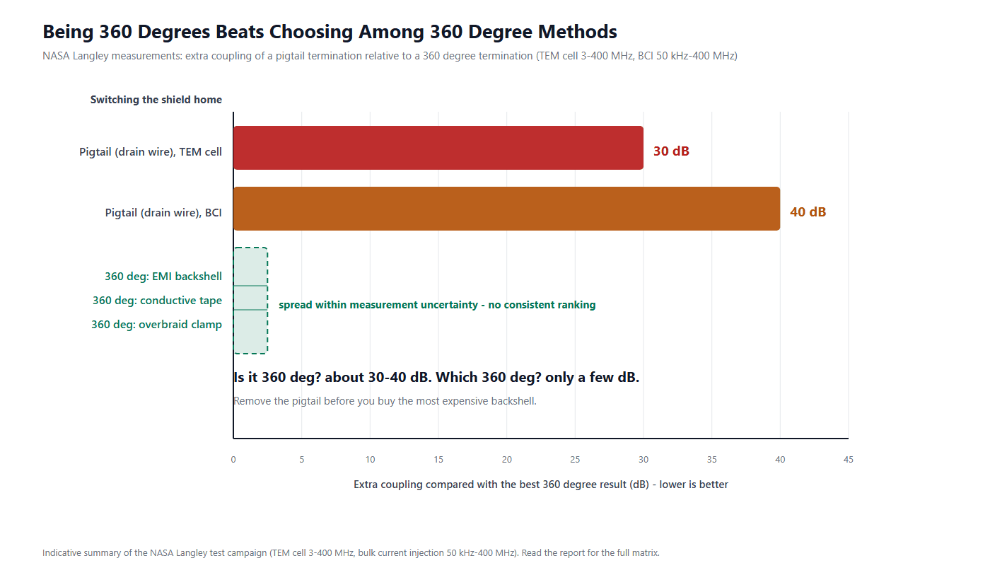
The most useful data here is not from a marketing department. NASA Langley measured pigtail against 360-degree terminations in a TEM cell from 3 MHz to 400 MHz and under bulk current injection from 50 kHz to 400 MHz. The pigtail was worse by roughly 30 dB in the TEM cell and roughly 40 dB under BCI — one campaign, one report, in the NASA test report, which is what makes the two numbers comparable.
The second half of the finding is the one that saves money. The 360-degree methods — an EMI backshell, conductive tape around the braid, an overbraid clamp — landed close together, with differences inside the spread of the measurement itself and no consistent ranking. Whether the shield is terminated through a full 360-degree contact matters far more than which 360-degree hardware you choose. Remove the pigtail first; compare backshells afterwards. PROFINET installation guidance follows the same logic, requiring a large contact area at both ends into the common bonding network rather than a specific part.
5. Grounding: the Wave-Length Test and the Shield-Current Criterion
“Ground the shield at one end only” is repeated so often that it is treated as a rule. It is not a rule, and no standard states it. The criterion is a length test against wavelength: below roughly 100 kHz a single-ended bond is the sensible default, because the cable is electrically tiny and a two-ended bond would close a power-frequency ground loop. Once the cable exceeds l > λ/20 at the highest significant frequency in the signal, the physics reverses and both ends must be bonded — the position taken in the shielding chapter of Keller’s Design for EMC. Above about 10 MHz, that means a full 360-degree ring contact into a metal connector body.
Put numbers on it. At 100 kHz the free-space wavelength is about 3000 m, so λ/20 is roughly 150 m. At 10 MHz the wavelength is 30 m and λ/20 is about 1.5 m. A 3 m to 15 m M12 trunk carries Ethernet or a fast fieldbus far beyond that threshold, so a single-ended shield on it is not conservative: it leaves the return path open.
At low frequency the arithmetic is simpler. There, Z_T collapses toward the DC resistance of the shield, and PROFIBUS & PROFINET International publishes the working figure of 10 to 15 mΩ/m for PROFIBUS and PROFINET cable shields in the PI earthing and shielding guide. The common-mode voltage is the shield current multiplied by that resistance and by the length.
| Shield current | 5 m run | 15 m run | PI band (Table 7.1) |
|---|---|---|---|
| 1 mA | 0.06 mV | 0.18 mV | below 5 mA: excellent |
| 30 mA | 1.8 mV | 5.4 mV | below 30 mA: no action needed |
| 100 mA | 6.0 mV | 18 mV | 30–100 mA: investigate |
| 300 mA | 18 mV | 54 mV | above 100 mA: must be resolved |
The right-hand column is the part to keep: under 5 mA is excellent, under 30 mA needs no action, 30 to 100 mA means investigate, and above 100 mA means fix — by removing the source, improving the mesh equipotential bonding or increasing the separation from power cables. Those are measured amperes, not opinions about grounding philosophy, and a two-ended shield is judged by that number rather than by the assumption that two-ended shields always cause trouble. Where a direct bond at one end is impossible, the accepted compromise is a hybrid: direct at one end and 10 nF or less at the other, which breaks the power-frequency loop while giving the high-frequency current a path (PI, Table 8.1, item 7.6). For the fieldbus side of the decision, see the site guide to industrial fieldbus cable selection, which covers the matching choices.
6. Field Checklist: Where Shielded Assemblies Actually Fail
The shielded vs unshielded cable decision is settled on the machine, not in a simulation. Every failure mode below is found with a caliper, a milliohm meter and a current clamp.
- Measure the pigtail. Folded-back braid with a ring terminal runs 30 to 80 mm — fine to 74 MHz against the budget above, a failure beyond it.
- Confirm the 360-degree contact. The shield must touch the shell all the way around under metal-to-metal pressure. If the answer is “the drain wire goes into a screw”, it is a pigtail whatever the drawing says.
- Bond both ends for any run past λ/20 — 1.5 m at 10 MHz — and for all high-frequency Ethernet, with a large contact area into the shared equipotential network.
- Clamp the shield current. Under 5 mA is excellent, under 30 mA is acceptable, above 100 mA must be fixed. A clamp meter on a live machine replaces a week of speculation.
- Ask for the balance figure, not only the shield:
a_c = a_s + a_u, and a Grade 1 shield cannot rescue a poor pair. - Do not upgrade the backshell first. The 360-degree methods are effectively equivalent, so the money belongs in removing the pigtail, then in the cable grade.
At HKWIRE, shielded M8 and M12 assemblies, overmolded cable assemblies and Ethernet patch cords are built to drawing: drain wire or full-ring termination, a stated pigtail length where one is unavoidable, and connector shells that give the shield a real 360-degree contact. Assemblies are produced to IPC/WHMA-A-620 workmanship practice — built to the standard rather than certified to it — under an ISO 9001 quality system, and material declarations are provided per project for RoHS and REACH review. For molded Ethernet and data assemblies, start from the Ethernet cable and patch cord range; for shielded sensor runs, the M12 connector coding guide explains which coding can carry your shield and your current at the same time. Where the shield has to survive both the field and the termination, the assemblies already in production are the M12 X-coded Cat6A to RJ45 cable, the Cat8 S/FTP patch cord, and the IP67 shielded RJ45 bulkhead coupler where the run enters a panel.
HKWIRE — shielded cable assemblies specified by number, not by adjective.
Send the cable grade, the termination method (360-degree ring or a defined pigtail length), the connector coding and the environment. We will quote the shielded vs unshielded cable assembly against your drawing and state the shield construction that goes into it.
7. FAQ
Is shielded vs unshielded cable simply a question of better and worse?
No. It compares two coupling budgets. A shield attenuates external fields and shield currents; it does not improve the balance of the pair, which decides how much common-mode disturbance becomes differential noise. If balance is poor, the shield’s contribution is added to a small number and the total stays small. Unshielded cabling is standardized on balance alone, which is why it works in electrically quiet, short runs.
How long can a pigtail be before it becomes the problem?
It has to be calculated. With a 100 mV limit at 5 mA of shield current — a 20 Ω return path — a 1 mm drain wire may be about 1990 mm at 1 MHz, about 267 mm at 10 MHz and only about 39 mm at 100 MHz. A 50 mm pigtail uses the whole budget at 74 MHz; halve the allowed voltage and every length halves.
Should the shield be grounded at one end or at both ends?
Below about 100 kHz, one end is the sensible default: the cable is electrically short and a two-ended bond invites a power-frequency loop. Above the λ/20 threshold — 1.5 m at 10 MHz — both ends must be bonded, and above roughly 10 MHz that bond should be a full 360-degree contact into a metal connector body. It is a length test against wavelength, not a preference: no standard requires single-ended bonding. Where a direct bond is impossible, 10 nF or less at the far end is the recognized compromise.
Do I need an expensive EMI backshell for a shielded cable?
Not as the first move. NASA put pigtails about 30 dB worse in a TEM cell and about 40 dB worse under bulk current injection than 360-degree terminations, while the 360-degree methods themselves — backshell, conductive tape, overbraid clamp — differed by less than the measurement spread. A true 360-degree contact is what matters; the hardware is secondary.
Is a foil-only shield enough for industrial Ethernet?
It depends on frequency and on your EMC margin. A single foil layer meets Grade 2: 1000 mΩ/m at 100 MHz against 60 mΩ/m for Grade 1, or 43.5 dB against 68.0 dB once converted with a_s = 20 lg (150 Ω / Z_TE). With single-digit margin, a shielded vs unshielded cable decision may still go to foil at that frequency; failing by tens of dB, only braid plus foil closes the gap.
How much shield current is too much?
PI publishes the working bands: under 5 mA is excellent, under 30 mA needs no action, 30 to 100 mA means investigate, above 100 mA must be fixed. At the published shield resistance of 10 to 15 mΩ/m, 300 mA over a 15 m run develops roughly 54 mV at 12 mΩ/m — small in absolute terms, but it adds to every other millivolt in the loop.







