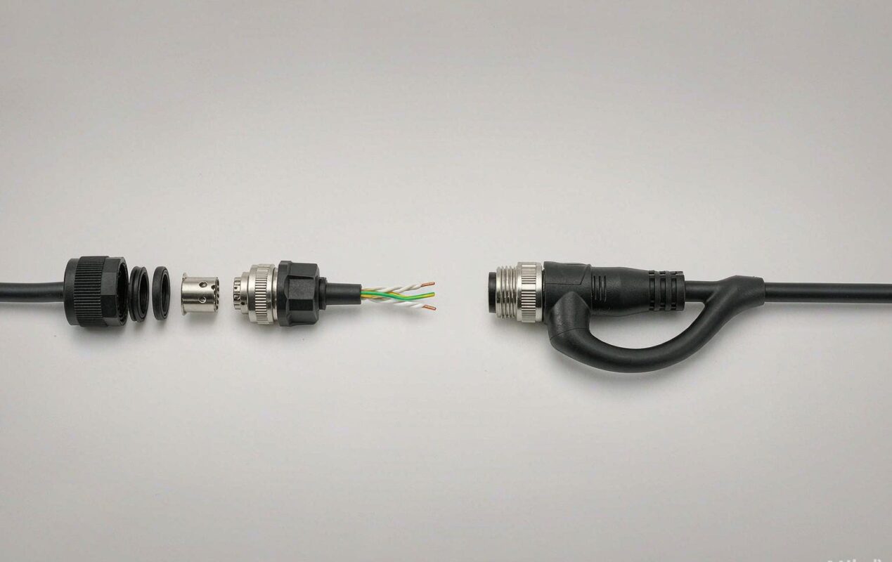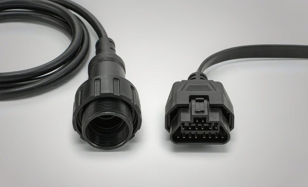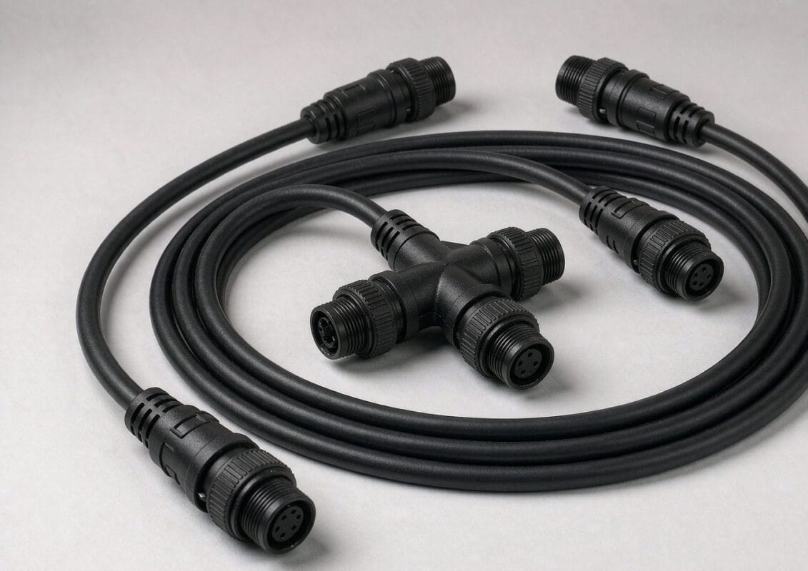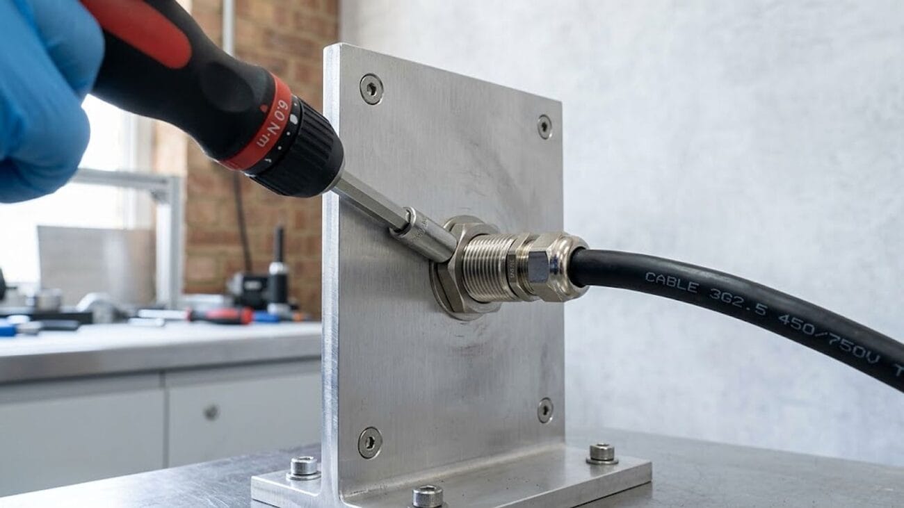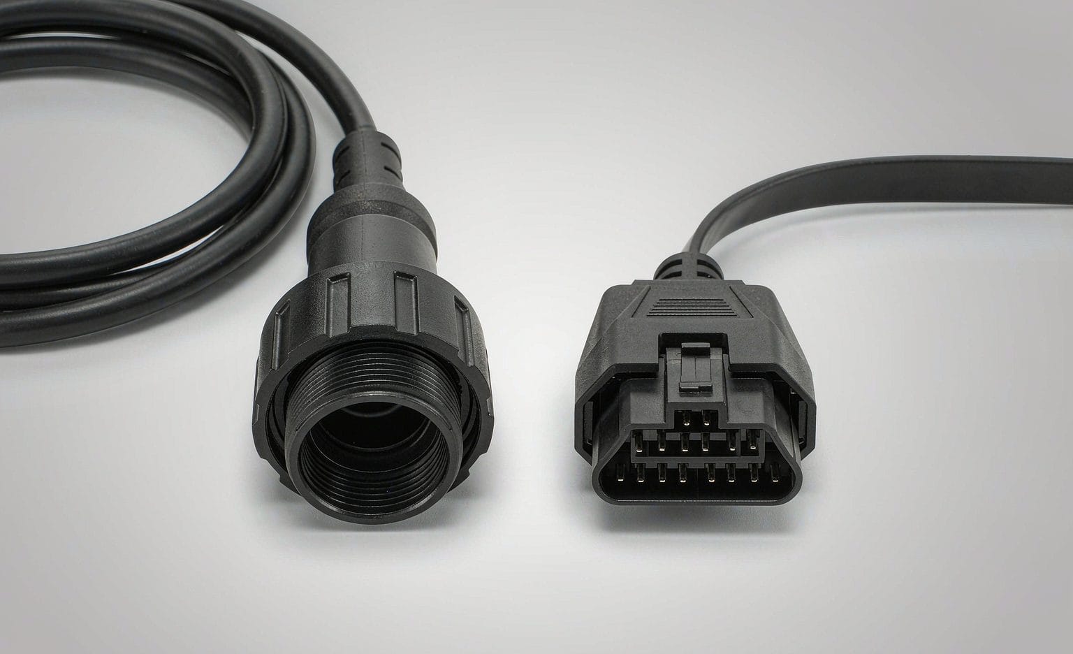
Two diagnostic ports sit within arm’s reach of a driver, and picking the wrong lead for either one is the most common way a fleet install goes sideways. J1939 vs OBD2 is not a question of which standard is better. It is a question of which connector is in front of you, what sits behind it, and what the cable has to carry. This guide sets the two side by side: the connector, the pinout, the bit rate, the way each one names data, and what all of that means for the harness you order.
J1939 vs OBD2: the connector tells you which world you are in
Look at the port first. A round 9-pin shell means a heavy vehicle and the SAE J1939 family of standards. A 16-pin trapezoid, two rows of eight in a D-shaped shell, means the light-duty OBD-II world defined by SAE J1962. They are not variants of one another. They come from different regulatory histories and they live on different vehicles.
The 9-pin is found in the cab of a Class 6–8 truck, on a tractor, on a generator set or on a marine auxiliary engine. The 16-pin lives under the dash of a passenger car or light truck, and the regulations put it within roughly two feet of the steering wheel. Where a heavy chassis presents a 16-pin shell instead, that is a deliberate exception rather than the rule, and it is the reason adapter leads exist at all.
One thing worth settling before the comparison: both of them run on the same physical network, a CAN bus. J1939 and OBD-II are two different diagnostic worlds built on top of it, which is why a cable builder can carry either one over the same copper with a different shell on the end.
Why two diagnostic ports exist at all
OBD-II came out of emissions enforcement. California’s Air Resources Board pushed on-board diagnostics from 1991, and the United States made OBD-II mandatory for cars and light trucks from the 1996 model year. From 2008 the US required ISO 15765-4, which is to say CAN, as the basis. The job was narrow and it was mandated: prove the emissions systems are working, report a standard set of results, and let any compliant tool read them.
J1939 came at it from the other direction. Heavy vehicle makers needed a network that the engine, transmission, ABS and aftertreatment control units could all share continuously while the machine did its work. Nobody mandated it. SAE published it and the industry adopted it because it solved a problem they actually had. Different starting points produce different interfaces, and they have not converged since.
Request-response versus continuous broadcast
This is the difference that decides what a cable has to survive.
OBD-II is a conversation. The tool asks and the vehicle answers. SAE J1979 defines the diagnostic test modes — current data, freeze frame, stored codes, pending codes, test results, vehicle information, permanent codes — and a list of parameter IDs, the PIDs, that a tool can request. Nothing is said unless something asks for it.
J1939 is a room where everyone talks at once. Control units broadcast parameter groups continuously on a schedule, and anything that wants the data listens. A fault is reported as a diagnostic trouble code built from a suspect parameter number, an SPN, a failure mode identifier, an FMI, and an occurrence count. That traffic does not stop while the key is on.
For the harness, continuous broadcast means the bus is always loaded and always sensitive to reflections, so stub length, twist and termination matter in a way they simply do not on a port that gets used for twenty minutes a month.
CAN bus bit rate: 250 kbit/s, 500 kbit/s and where each shows up
J1939 runs on CAN with a 29-bit identifier, and the physical layer documents set the numbers:
| Document | Media | Bit rate | Max stub | Max bus length | Max ECUs |
|---|---|---|---|---|---|
| J1939-11 | Shielded twisted pair | 250 kbit/s | 1 m | 40 m | 30 |
| J1939-14 | Shielded or unshielded | 500 kbit/s | 1.67 m | 40–56.4 m | 30 |
| J1939-15 | Unshielded twisted pair | 250 kbit/s | 3 m | 40 m | 30 |
All three specify 120 ohm nominal cable impedance and a 120 ohm terminating resistor at each end of the trunk. OBD-II over CAN is ISO 15765-4, and both 250 kbit/s and 500 kbit/s occur in the field, with 11-bit or 29-bit identifiers depending on the vehicle.
The practical consequence is that bit rate is set on the vehicle side, not in the cable. A passive adapter cannot change it. What a cable can change — and what actually breaks networks — is stub length, termination, and whether the twist survives the joint.
The 9-pin round port, pin by pin
SAE J1939-13 defines the off-board diagnostic connector: a nine-position round shell lettered A through J with I skipped, built around Deutsch HD10-series hardware. The assignment below is the one most vehicle and tool makers publish for it. It is the industry definition of the interface, not a statement about your particular chassis — H and J in particular are manufacturer discretion, and we populate the pins you tell us to populate.
| Pin | Commonly published function | Note |
|---|---|---|
| A | Battery / chassis negative return | Reference point for the shield drain |
| B | Unswitched battery positive | Live with the key off |
| C | J1939 CAN High | The pair your tool listens on |
| D | J1939 CAN Low | The pair your tool listens on |
| E | Shield / drain | Terminated at the shell, not at a pin |
| F | J1708 data positive | Legacy link on older chassis |
| G | J1708 data negative | Legacy link on older chassis |
| H | Manufacturer discretion | Assignment varies by maker |
| J | Manufacturer discretion | Assignment varies by maker |
Two of those pins are a power supply. A and B carry battery negative and unswitched battery positive, and that is what keeps a tracker or an ELD alive with the key off. It is also how a port fuse gets found the hard way: B is live, and shorting it to A with a test lead is a memorable lesson.
One field check is worth knowing. With the key off and nothing plugged in, a healthy terminated bus reads roughly 60 ohms across C and D, because the two 120 ohm terminators are in parallel. Read 120 ohms and one of them is gone. Read open or a dead short and go looking for damage before you blame the tool.
Type 1 black and Type 2 green: the keying that stops mistakes
The 9-pin port comes in two keyed variants and they are deliberately not interchangeable. Type 1 is black. Type 2 is green, and the keying is arranged so that a green plug will still mate with a black socket but not the other way round.
The reason is bit rate. Type 2 arrived with 500 kbit/s capability, and the newer connector was keyed so that an older tool which cannot read 500 kbit/s cannot be connected to a bus running at it. In practice the two also differ in which pins carry which network: on Type 2 implementations the 250 kbit/s diagnostic network often sits on F and G, or on H and J, rather than on C and D. That is the trap — a tool that asks for fault codes on C and D gets no answer if the bus it wants is on another pair.
Shell color fades and gets repainted, so read the keyway and the build year alongside it. A photograph of the port plus make, model and year is enough for us to confirm which variant ships. Our J1939 Type 1 adapter and the rest of the 9-pin range are built to the pinout you send rather than to one assumed standard.
The 16-pin J1962 port, pin by pin
OBD-II uses the SAE J1962 connector: a female 16-pin D-shaped shell in two rows of eight. Type A is for 12 V vehicles and Type B for 24 V. A Type B shell is marked and keyed so a Type A plug will not go in, although a Type B plug will fit a Type A socket.
| Pin | Function | Pin | Function |
|---|---|---|---|
| 2 | SAE J1850 bus positive | 10 | SAE J1850 bus negative (PWM only) |
| 4 | Chassis ground | 11 | Manufacturer discretion |
| 5 | Signal ground | 12 | Manufacturer discretion |
| 6 | CAN High (ISO 15765-4) | 13 | Manufacturer discretion |
| 7 | K-line (ISO 9141-2 / ISO 14230-4) | 14 | CAN Low (ISO 15765-4) |
| 8 | Manufacturer discretion | 15 | L-line (ISO 9141-2) |
| 9 | Manufacturer discretion | 16 | Battery positive, unswitched |
Most of what plugs into a port today needs only four or five of those: 4 or 5 for ground, 6 and 14 for the CAN pair, and 16 for power. The K-line and L-line positions belong to older serial protocols. Pins 1, 3, 8, 9, 11, 12 and 13 are whatever the maker decided, which is why a pin list for the specific platform beats a generic chart every time.
Type A and Type B: why we do not publish one Type B chart
Type A is defined. SAE J1962 fixes the connector and the assignment for on-board diagnostics, so CAN sits on 6 and 14 and battery on 16. Type B is not one thing. It is a family of chassis-level assignments that share a shell and a mounting position, and several of them differ from one another as much as they differ from Type A. Any page that prints a single Type B chart is guessing.
That is why our OBD2 Type B cable is built to the definition you supply, and why every build ships with a printed pinout card so the next installer does not have to guess either. Send us the pinout, or send a known-good cable and we will copy it.
How each side names data
Different vocabularies, and it matters when you are specifying a lead for a fleet tool.
OBD-II works in modes and PIDs. SAE J1979 defines the test modes and a set of standard parameter IDs, and manufacturers add their own on top of those. A request names a mode and a PID; the response carries the value.
J1939 works in parameter groups. A PGN identifies the message, an SPN identifies the individual value inside it, and an FMI says what is wrong with it. The 29-bit CAN identifier carries priority, the PGN, a destination and a source address, and every node on the bus claims an address of its own.
Neither scheme holds “more data” than the other. They are different indexing systems built for different jobs, and a passive cable does not translate between them. A J1708 message does not become a J1939 message, and a J1939 broadcast does not become an OBD-II response.
What the cable actually has to carry
Strip the protocols away and a diagnostic lead is doing four things:
- Carrying a differential pair with controlled impedance and the twist intact, so the bus still looks like a bus at the far end.
- Carrying the shield or drain through, continuously, and terminating it where the drawing says — not wherever happens to be convenient.
- Carrying power, which means conductor sized to the combined draw of everything left plugged in, not sized to the signal.
- Surviving the environment: vibration, temperature cycling, oil, road salt, and a connector that will be pulled on.
That last point is where the two worlds diverge most. A passenger-car diagnostic lead lives a sheltered life behind the dash. A J1939 harness on a truck, a combine or an excavator lives with continuous vibration, a wide temperature range and moisture at the connector face, so shielding, connector retention and jacket choice carry more weight than they do on a car lead. Our Deutsch DT 6-pin heavy-duty diagnostic cable is built for exactly that duty.
Four ways to tap a bus, and what each one costs the network
Every fleet guide on this topic describes the same ways to get at vehicle data, and every one of them stops at the software: which protocol, which decoder, which cloud. What none of them can tell you is what each access method does to the bus electrically, because that depends on how the lead is built. This is the part that belongs to the harness.
| Access method | What it adds to the bus | What it does to the vehicle | Margin left | What it suits |
|---|---|---|---|---|
| In-line extension | Cable length, no branch | Nothing; unplugs in seconds | Most | Moving the port somewhere an installer can reach |
| Molded Y splitter | One short, controlled stub | Nothing permanent; reversible | Comfortable for two devices | A device that must stay connected plus a port the service bay still needs |
| Breakout harness | A branch to flying leads or terminals | Semi-permanent wiring behind the dash | Depends on branch length | Hardwired units that must not be unplugged by a driver |
| Direct tap at a gateway or ECU | Whatever length you run | Modifies the factory harness | Least | Only when the port does not carry the bus you need |
Two rules fall out of that table. The first is that a branch is a stub, and a stub is spent budget: J1939-11 allows 1 m, J1939-14 allows 1.67 m and J1939-15 allows 3 m, and those figures are a ceiling, not a target to aim for. The second is that bit rate belongs to the vehicle and the controllers at each end, never to the copper — making a lead longer or shorter will not change it, but making the branch longer will change whether the bits arrive intact.
That is also the honest limit of a direct tap. Where a vehicle isolates its diagnostic port behind a gateway module, what sits on the port pins is not necessarily everything the control units are saying, and tapping further in means cutting into a factory harness with a warranty attached. Start at the port unless you have a reason not to.
If you take one thing from this section: the three numbers that decide a diagnostic lead are the bit rate you must not exceed, the stub budget you are spending, and the supply current you have to share. Everything after that is connector choice.
What a symptom usually means
Faults on a diagnostic port get blamed on the tool far more often than they should. This is the order we work through when a customer tells us a lead does not work.
| Symptom | Check first | Usual cause |
|---|---|---|
| Tool powers up, no data | Which pins actually carry the bus, and at what rate | Pinout mismatch, not a cable fault — on Type 2 ports the 250 kbit/s pair is often on F/G or H/J, not C/D |
| About 120 ohms across the pair | Termination | One of the two terminators is missing or disconnected |
| Open circuit or a dead short | The pair itself | Damage in the vehicle harness; a new lead will not fix it |
| Works at the port, drops out on the road | Connector retention and strain relief | An unsupported lead hanging off the port, working the shell loose |
| Fine with one device, breaks with two | Supply current and added stub | Shared pins A and B, or the second branch pushed past the stub budget |
| Fine in the yard, fails under load | Branch length and joint quality | A long hand-made stub reflecting once the bus is busy |
| Intermittent and never reproducible | Mechanical support | Weight on the port, or a joint made without strain relief |
Two of those seven are cable problems, two are vehicle problems, and the first one is almost always a pinout problem. That is why we ask for a photograph of the port and the pin list before quoting rather than after.
Deutsch shells: HD10, DT and the rest of the family
The round diagnostic connector is HD10-series hardware: an environmentally sealed thermoplastic cylindrical shell with three to nine cavities and bayonet coupling, and it is the series the diagnostics industry standardised on. The rest of the Deutsch family turns up further down the same harness.
| Series | Contact size | Current per contact | Cavity arrangements | Typical use |
|---|---|---|---|---|
| HD10 | 16 (also 12, 4) | 13 A | 3, 4, 6, 9 | Diagnostic connectors |
| DT | 16 | 13 A | 2, 3, 4, 6, 8, 12 | General transport and machine wiring |
| DTM | 20 | 7.5 A | 2, 3, 4, 6, 8, 12 | Sensors and signal circuits |
| DTP | 12 | 25 A | 2, 4 | Power circuits |
| HD30 | 16 | 13 A | multi-pin | Metal shell, bayonet, heavy duty |
Where a machine presents a Deutsch DT port rather than a 9-pin diagnostic port, a DT06 to J1939 adapter bridges the two without pretending to convert anything, and a DT connector pigtail harness breaks the circuit out into flying leads when that is what the install needs.
J1939 vs OBD2: choosing from the vehicle, not the catalog
Work backwards from the port.
- Identify the connector. Round 9-pin, or 16-pin J1962.
- Identify the variant. Type 1 or Type 2 on the round port; Type A or a named Type B assignment on the 16-pin.
- Confirm which pins carry the network you need. C and D on a classic 9-pin, but not always on Type 2. Pins 6 and 14 on Type A, and verify rather than assume on Type B.
- Confirm the bit rate. It is set by the vehicle. If your tool only does one rate, that decides the adapter.
- Write down what else has to sit on the port permanently, and add up the current.
That last step is the one that gets skipped. A J1939 9-pin Y splitter lets a telematics device stay connected while a technician still gets a live port, but the supply pins are shared, so every device left plugged in draws from the same path. Add the draw of the tracker, the ELD and anything else before you assume it will all run, particularly on a vehicle that parks for a week.
Where the two worlds genuinely have to meet on one lead, a J1939 to OBD2 diagnostic cable is the straight-through answer, and an OBD2 extension cable is what moves a port to somewhere an installer can reach.
Where this meets NMEA 2000 and ISO 11783
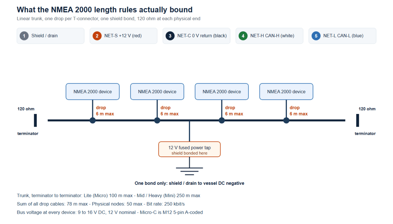
J1939 is the parent of several other networks, and two of them are worth knowing here. ISO 11783 is the agricultural version, the bus between a tractor and its implements. NMEA 2000 is the marine one, and it borrows the J1939 high-level protocol and runs it at the same 250 kbit/s.
That shared ancestry is why engine data from a marine diesel can reach a chartplotter without a gateway in between, and it is why the cabling discipline is the same in all three: linear bus, controlled impedance, two terminators, short stubs. If you already understand one of them, the other two are mostly a vocabulary exercise. The network design rules on the marine side — backbone length, termination and power budget — are set out in our NMEA 2000 backbone design guide, and the M12 CAN bus cable covers the same bus in an industrial connector.
How we build and verify a diagnostic lead
Every J1939 and OBD2 assembly is built to the pinout on your drawing rather than to an assumed standard, because the assignment varies by maker and by platform. Conductors are tinned copper. The build standard is IPC/WHMA-A-620 Class 3 under ISO 9001, with terminations from 32 to 12 AWG.
Testing is 100% continuity and pinout on every unit before it is packed. Where the drawing carries an ingress rating, seal checking is quoted to it. Insulation resistance, dielectric withstand and retention are tested to the values you specify, and material declarations against RoHS and REACH are issued per project. We do not claim an approval we do not hold: where your drawing names a UL style or another approval, the build follows your drawing and ships with the supporting document rather than a claim of ours.
Samples, tooling and minimum order quantities
Prototype lots run from 1 to 50 pieces. Production runs start at 500 pieces per part number. If the design needs molded parts we do not already hold, the tooling is cut in our own tool room, adds around ten working days, and belongs to your program — so a repeat run years later starts from the same tool. If all you have is a known-good cable, we can reverse engineer it and return a first article for approval before production. The full range sits under automotive cable and wire harness, and the wider program is described on our automotive and EV page.
Frequently asked questions
Is J1939 the same thing as OBD2?
No. OBD-II is a mandated emissions diagnostic interface for light vehicles, built on the SAE J1962 16-pin connector and a request-response model. J1939 is the working network inside heavy vehicles, accessed through a 9-pin round connector defined in SAE J1939-13, and its devices broadcast continuously. They share a CAN physical layer and nothing else.
Can one cable work on both?
Physically yes, with the right connectors on each end, and that is what a J1939 to OBD2 adapter lead is. Electrically it is straight-through wiring: it carries the bus from one shell to the other and converts nothing.
Which pins does a modern 16-pin port actually need?
Ground on pin 4 or 5, the CAN pair on 6 and 14, and power on 16. Everything else depends on the platform and on what the tool is capable of.
How do I tell Type 1 from Type 2 on a 9-pin port?
Shell color is the quick answer — black is Type 1, green is Type 2 — but shells fade. Read the keyway and the build year alongside the color, and confirm against the pin list in the service manual. A photograph plus make, model and year is enough for us to confirm the variant.
Will an adapter change a 250 kbit/s bus to 500 kbit/s?
No. Bit rate is set on the vehicle side and a passive cable cannot change it. If your tool only speaks one rate, that decides which port and which adapter you can use.
Can I leave a tracker connected and still give the technician a live port?
Yes, with a molded Y splitter rather than a hand-made tee. A bench splice introduces two unmatched stubs and no strain relief, which is exactly the combination that produces faults that appear under load and never reproduce in the yard.
Do I need a terminating resistor in the lead?
Usually not. Fit one only if the network is missing its terminations. Adding a third 120 ohm resistor to a bus that already has two will pull it out of specification.
What should I read across CAN High and CAN Low?
Roughly 60 ohms with the key off and nothing plugged in, because the two 120 ohm terminators are in parallel. Reading 120 ohms means one is missing; an open circuit or a dead short means go and find the damage.
Can you build to a sample instead of a drawing?
Yes. Send the cable or the connector, and we will reverse engineer it, confirm the pinout back to you in writing, and return a first article before production.
Do you supply SAE J1939 certified cable?
We build to the cable and connector specification you name on the drawing, including the constructions the J1939 physical layer documents describe. Certification of the finished network belongs to the device makers and the installer, and we do not claim an approval we do not hold.
Can I tap the bus somewhere other than the port?
Technically yes, and sometimes it is the only way to reach the bus you need. But it means cutting into the factory harness, and on vehicles that isolate the port behind a gateway module the traffic on the port pins may already be filtered. Start at the port, and only move inward when you have confirmed the port does not carry what you want.
How long can the lead be?
Branch length is the constraint, not total cable length. Keep the branch inside the stub budget for the network you are on — 1 m on a J1939-11 bus, 1.67 m on J1939-14 — and treat a longer run as a design question rather than a catalog question. Tell us the run and the network and we will size the pair to it.
Send us the port and the pin list
Send a photograph of the port, the vehicle or machine make, model and year, the pinout if you have it, and what has to stay plugged in. We will confirm the connector variant, build to your pin list rather than an assumed standard, and quote the assembly, the terminations and any molded parts together. Wiring practice on the conductor side is covered in our automotive wire harness selection guide if you are sizing the harness at the same time.
References
The technical claims in this guide come from the published editions of the documents below. Where a document is listed without a link, the standards body does not serve that page to automated agents, so it is cited by name and scope rather than risk pointing at a page we cannot verify.
- SAE J1939 — heavy-duty vehicle network, top level document.
- SAE J1939-11 — physical layer, 250 kbit/s, shielded twisted pair.
- SAE J1939-13 — off-board diagnostic connector, the 9-pin round shell.
- SAE J1939-14 — physical layer, 500 kbit/s.
- SAE J1939-15 — physical layer, 250 kbit/s, unshielded twisted pair.
- SAE J1962 — 16-pin diagnostic connector, Type A and Type B.
- SAE J1979 — E/E diagnostic test modes for OBD-II.
- ISO 11898-2 — Controller Area Network (CAN), part 2: high-speed medium access unit.
- ISO 15765-4 — Diagnostic communication over Controller Area Network, part 4: requirements for emissions-related systems.
- ISO 15031-3 — Road vehicles, communication between vehicle and external equipment for emissions-related diagnostics.