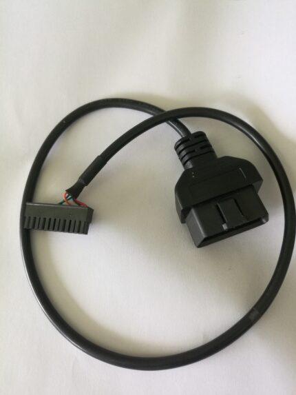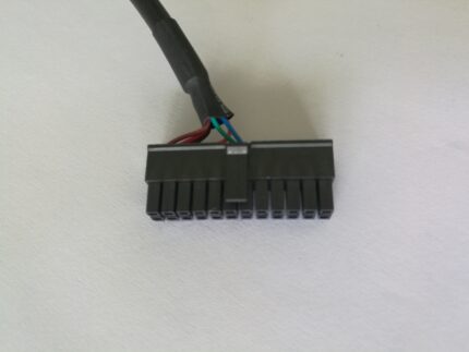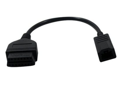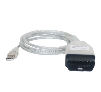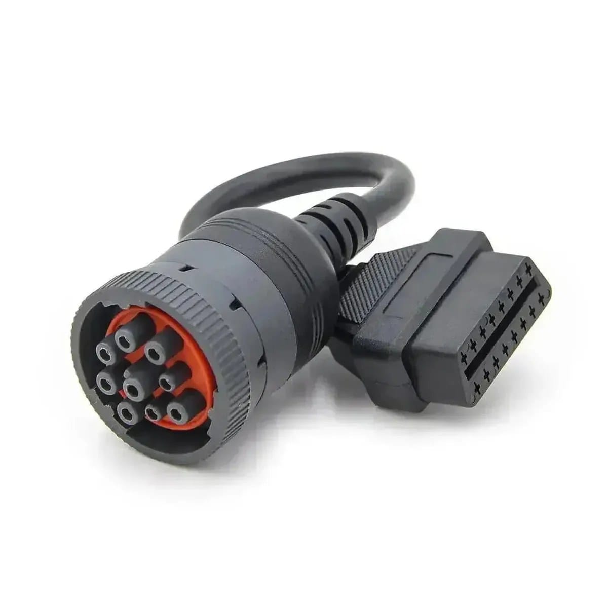
SAE J1939 OBD2 Diagnostic Cable, Type 2 Green 9-Pin to 16-Pin Adapter
This J1939 OBD2 diagnostic cable is a Type 2 green 9-pin plug to J1962 16-pin socket, built for heavy trucks and machines that expose the diagnostic bus on a round port. Passive, shielded, no protocol conversion, wired to the pinout you send.
Last updated: 13 September 2026
Overview
A J1939 OBD2 diagnostic cable takes the round 9-pin diagnostic port found on
heavy vehicles and presents it as the familiar J1962 16-pin socket, so one scan tool, fault
reader or telematics dongle can work across a whole fleet. This is the Type 2 build: green
shell, the assignment used on most North American heavy trucks from the mid-2010s onward and on
a lot of construction and farm machines. It carries the CAN pair together with battery and
ground. It is a passive wiring adapter, not a protocol converter, and the bit rate it works at
is decided by the vehicle and the tool, not by the cable.
Key Specifications
| Connector A | 9-pin round diagnostic plug, green shell, flange lock, compatible with Deutsch HD10 / HD16 series |
|---|---|
| Connector B | J1962 16-pin female socket |
| Wiring | CAN-H, CAN-L, battery and ground |
| Conductor size | 20 to 18 AWG tinned copper |
| Shielding | Aluminum foil plus tinned copper braid |
| Jacket | Oil-resistant PVC or TPU |
| Voltage | 12 V and 24 V systems |
| Length | 0.3 m / 0.5 m / 1 m |
| Function | Passive wiring adapter, no protocol conversion |
| Shell variant | Type 2 green standard; Type 1 black shell to order for older vehicles |
| Data rate | 250 kbps and 500 kbps backbone assignments, wired per the pinout you send |
| Tool side | Passive adapter; protocol and bit rate are set by your scan tool, not by the cable |
The 9-pin pinout, letter by letter
The shell is a 9-position round connector with pins identified A through J — there is no I,
which trips people up the first time they read a pinout chart. The physical shell is the same
across the Deutsch HD10 and HD16 families; what changes between vehicle makers is what sits in
each cavity. Treat the table below as the common assignment, not as a guarantee, and build to
the pinout you measure or the one your tool vendor publishes.
| Pin | Signal | Type 2 (green shell) | Type 1 (black shell) |
|---|---|---|---|
| A | Battery negative | Ground | Ground |
| B | Battery positive | Unswitched 12 V or 24 V | Unswitched 12 V or 24 V |
| C | CAN high | J1939 backbone, 500 kbps class | J1939, 250 kbps |
| D | CAN low | J1939 backbone, 500 kbps class | J1939, 250 kbps |
| E | CAN shield | Shield ground | Shield ground |
| F | Second pair or legacy | CAN 2 high, or J1708 / J1587 high | J1708 / J1587 high |
| G | Second pair or legacy | CAN 2 low, or J1708 / J1587 low | J1708 / J1587 low |
| H | OEM defined | Often a second CAN channel or auxiliary | Often unused or auxiliary power |
| J | OEM defined | Often a second CAN channel or auxiliary | Often unused or auxiliary power |
That split between the two shells is where most wasted service hours come from. A tool that
expects the 250 kbps network on C and D will sit there silent on a truck where the 250 kbps
traffic lives on F and G, or on H and J, while C and D run at the faster backbone rate. The
shell color tells you which world you are in before you plug anything in.
Type 1 and Type 2 are not interchangeable
Same shell, same pin letters, different assignment. The two variants are keyed differently by
color and by the flange, and one will not substitute for the other in a mixed fleet.
- Type 2, green shell — the usual fitment on 2015-and-later North American
heavy trucks and on many current construction and agricultural machines. Commonly quoted at
500 kbps on the backbone pair with a second channel or the legacy link on the second pair. - Type 1, black shell — still found on older tractors, coaches, generator
sets and a large share of the European parc. Commonly quoted at 250 kbps with the legacy
J1708 pair alongside. - Mixed fleets — stock both. The cost of one wrong adapter is a truck off
the road for a day, which dwarfs the price of the part.
250 kbps and 500 kbps: where the number actually lives
Bit rate belongs to the network and the controllers on each end, not to the copper. What the
cable contributes is length and balance: keep the run short, keep the pair twist up to the
contact, and terminate the drain properly, or you lose the margin the network needs at the higher
rate. That is why the stock lengths stop at 1 m.
Passive means passive
There is no chip in this cable. It does not translate between SAE J1939, SAE J1708 or any manufacturer-specific protocol,
and if your tool asks for a message the vehicle does not broadcast, this cable will not invent
it.
Construction
- Conductors for the CAN pair, battery and ground at 20 to 18 AWG, sized so voltage drop is
negligible at the lengths offered. - Aluminum foil plus tinned copper braid over the signal pair, with the drain terminated at
the connector end. - Oil-resistant PVC or TPU jacket for routing past engines, gearboxes and hydraulic lines.
- Overmolded strain relief at both connector bodies, which is where this type of cable
normally fails first.
Lengths and options
Stock lengths are 0.3 m, 0.5 m and 1 m. The 0.3 m version holds the tool clear of the dash
panel; 1 m is the choice when the reader sits on a bench or a cart beside the cab. Longer runs,
right-angle bodies, unshielded cost-reduced builds and private-label overmold tooling are
available on request.
How to specify your build
- Shell color — green Type 2 or black Type 1, read off the vehicle port.
- Pin assignment — the standard one, or the one your tool vendor
documents. - Length and whether you need a right-angle body.
- Jacket — PVC for cab routing, TPU where it will see oil and weather.
- Quantity, and whether you want both shell types in one shipment.
Typical applications for this J1939 OBD2 diagnostic cable
- Fleet service bays standardizing one scan tool across mixed model years
- Telematics dongles that need a J1962 socket on a truck with a round 9-pin port
- Roadside service vans working on construction and agricultural machines
- Diagnostic port extensions alongside our J1939
9-Pin Y Splitter Cable for ELD and GPS trackers - Workshops that still carry legacy tooling, paired with our black
9-pin J1939 Type 1 adapter
Workmanship and testing
Assembly and inspection follow IPC/WHMA-A-620 Class 3 workmanship criteria under our ISO 9001 quality management system, and every unit passes 100% continuity and pinout testing before it is packed. Conductor range is 32 to 12 AWG. Where an ingress rating is specified we can quote seal checking on the production batch.
Custom builds and ordering
Prototypes run from 5 pcs with a 3 working day turnaround; volume orders start at MOQ 500 pcs
and ship 14 working days after sample sign-off. OEM and ODM orders ship under your part number
and labeling.
Related diagnostic leads
- J1939 9-Pin Y Splitter
Cable for ELD and GPS Trackers - Black 9-Pin J1939 Type 1
Adapter to OBD2 16-Pin Socket - DT06 to J1939 Adapter Cable
for Tractors and Excavators - Heavy-Duty
9-Pin Industrial Diagnostic Cable Assembly - OBD-II
16-Pin to DB9 CAN Bus Diagnostic Cable, 25 ft
Full range: automotive
cable and wire harness.
Frequently Asked Questions
How do I know if I need Type 1 or Type 2?
Look at the port on the vehicle. Green shell is Type 2, black shell is Type 1. If the port is
dirty, wipe it: the color is the fastest identification you have, and the two are keyed
differently.
Does this cable convert J1708 to J1939?
No. It is a passive wiring adapter. It carries whatever the vehicle puts on the pins, and
your tool still has to speak the protocol the vehicle uses.
Can I use it on a 24 V truck?
Yes, the build covers 12 V and 24 V systems. Confirm the system voltage when you order so the
pin assignment and the conductor sizing match.
What length should I buy?
0.3 m for a hand-held tool at the dash, 0.5 m for general bay work, 1 m when the reader sits
on a bench or a cart beside the cab.
Can you wire it to a non-standard pinout?
Yes. Send the pin assignment and we build to it rather than to the common default. That is
usually what fleet customers with a house tool end up doing.
| Connector A | 9-pin round diagnostic plug, green shell, flange lock, compatible with Deutsch HD10 / HD16 series |
|---|---|
| Connector B | J1962 16-pin female socket |
| Wiring | CAN-H, CAN-L, battery and ground |
| Conductor size | 20 to 18 AWG tinned copper |
| Shielding | Aluminum foil plus tinned copper braid |
| Jacket | Oil-resistant PVC or TPU |
| Voltage | 12 V and 24 V systems |
| Length | 0.3 m / 0.5 m / 1 m |
| Function | Passive wiring adapter, no protocol conversion |
| Shell variant | Type 2 green standard; Type 1 black shell to order for older vehicles |
| Data rate | 250 kbps and 500 kbps backbone assignments, wired per the pinout you send |
| Tool side | Passive adapter; protocol and bit rate are set by your scan tool, not by the cable |