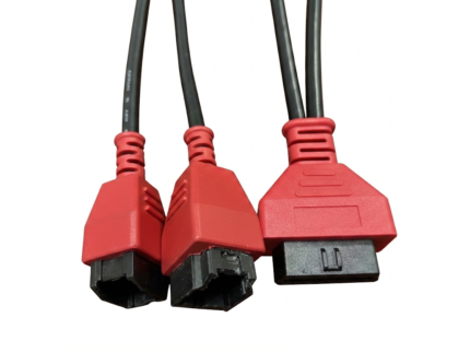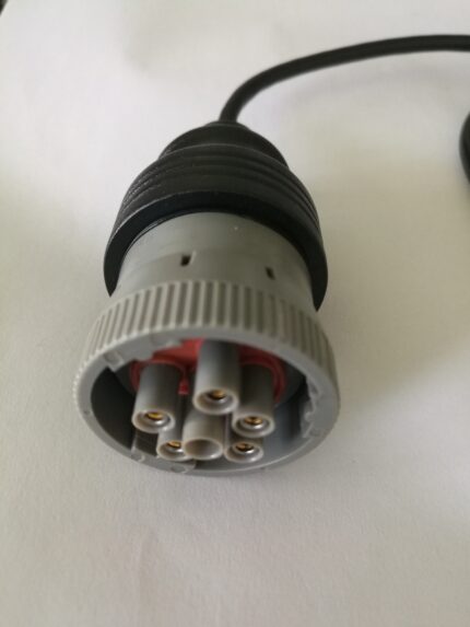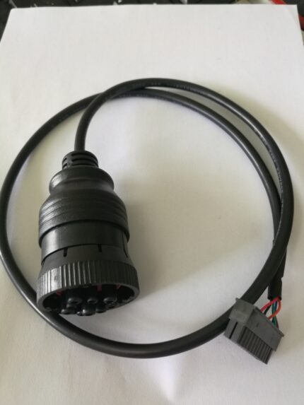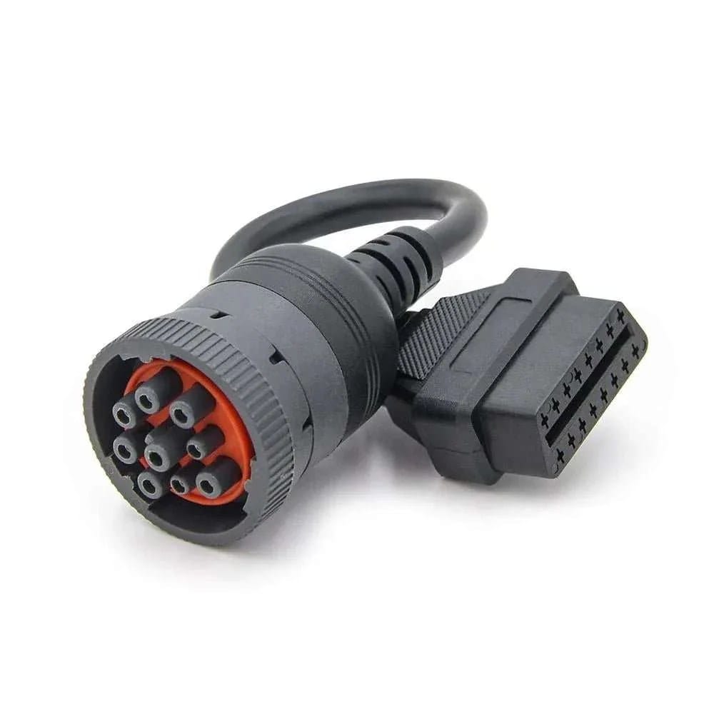
Black 9-Pin J1939 Type 1 Adapter to OBD2 16-Pin Diagnostic Socket
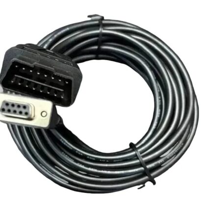
A j1939 type 1 adapter takes the black 9-pin diagnostic port found on older trucks, buses and generator sets and presents it as a J1962 16-pin socket, so a standard scan tool can read the CAN bus. Wired passive, 12 V or 24 V, built to the pinout you send.
Last updated: 13 September 2026
Overview
A j1939 type 1 adapter joins two generations of heavy-duty diagnostic port: the black 9-pin round connector that came before the green Type 2 port, and the J1962 16-pin socket that nearly every scan tool, code reader and fleet dongle is made to plug into. There is no electronics in between. The adapter takes the CAN pair, battery and ground from the 9-pin side and lands them on the pins a generic tool expects, so whatever the vehicle does or does not put on the bus is exactly what reaches your tool. We build it to the pinout on your drawing rather than to a generic chart, in the length, jacket and shielding your routing needs.
Key Specifications
| Connector A | 9-pin round diagnostic plug, black shell, built to the Deutsch HD10 / HD16 series interface |
|---|---|
| Connector B | J1962 16-pin female socket |
| Wiring | CAN-H, CAN-L, battery and ground, wired passive |
| Conductor | Tinned copper, 20 to 18 AWG |
| Shielding | Foil plus braid, drain terminated at the shell |
| Jacket | Oil-resistant PVC or TPU |
| System voltage | 12 V / 24 V |
| Length | 0.3 m / 0.5 m / 1 m, custom on request |
| Function | Passive adapter, no protocol conversion |
Type 1 or Type 2: identifying the port in front of you
Shell color is the quick answer, but shells fade and get repainted, so read the keyway and the build year alongside it. The two connectors are deliberately not interchangeable — that is the whole point of the keying, and it is why forcing a Type 2 plug into a Type 1 port is a workshop argument waiting to happen.
| Check | Type 1 (this adapter) | Type 2 (green) |
|---|---|---|
| Shell color | Black | Green |
| Keying | Round 9-pin, Type 1 keyway | Round 9-pin, Type 2 keyway |
| Commonly found on | Pre-2015 heavy trucks and tractors, gensets, marine auxiliary engines | Later heavy trucks, coaches and buses |
| Buses normally present | J1939 CAN, often J1708 alongside it | J1939 CAN |
| Adapter you need | This one | A Type 2 lead |
If the color is gone, the keyway position settles it and the pin list in the service manual confirms it. A photograph of the port, plus vehicle make, model and year, is enough for us to confirm which variant ships.
The 9-pin pins you are connecting to
The round 9-pin diagnostic connector is defined in SAE J1939-13, and the assignment below is the one most vehicle and tool makers publish for it. It sits alongside the SAE J1939 family of standards that define the bus itself. It is the industry-published definition of the interface, not a statement about your particular chassis.
| Pin | Commonly published function | Note |
|---|---|---|
| A | Battery / chassis negative return | Reference point for the shield drain |
| B | Unswitched battery positive | Feeds pin 16 on the 16-pin side |
| C | J1939 CAN High | The pair your tool listens on |
| D | J1939 CAN Low | The pair your tool listens on |
| E | Shield / drain | Terminated at the connector shell, not at a pin |
| F | J1708 / ATA data positive | Present on older chassis with the legacy bus |
| G | J1708 / ATA data negative | Present on older chassis with the legacy bus |
| H | Manufacturer discretion | Assignment varies by maker |
| J | Manufacturer discretion | Assignment varies by maker |
We populate the pins you tell us to populate. If your H and J positions carry a proprietary line, send the list and we will bring it across; if they are empty, we leave them empty.
What arrives at the 16-pin socket
| J1962 pin | Function | Fed from 9-pin pin |
|---|---|---|
| 4 | Chassis ground | A |
| 5 | Signal ground | A or E, per your drawing |
| 6 | CAN High (ISO 15765) | C |
| 14 | CAN Low (ISO 15765) | D |
| 16 | Battery positive | B |
Pins 4, 5, 6, 14 and 16 are what a generic tool needs to wake up and start talking. Where a fleet tool expects J1708 or a maker-specific line, we can bring those across onto the manufacturer-discretion positions of the 16-pin side, but only against your written pin list.
What a passive adapter will not do
- Convert protocols. A J1708 message does not become a J1939 message. If your tool only speaks one of them, buy a tool or an active gateway that speaks the other.
- Supply a missing bus. If the vehicle does not put J1939 on pins C and D, nothing appears at the socket.
- Change the baud rate. 250 kbit/s and 500 kbit/s are set on the vehicle side.
- Repair a damaged port. Bent pins, spread sockets and green corrosion in the vehicle connector are a harness repair, not an adapter problem.
Length, jacket and shielding
Inside a cab, shorter is nearly always better — excess coiled cable ends up under the clutch pedal. 0.3 m suits a tool held at the port, 0.5 m and 1 m suit a reader on the passenger seat or a workshop trolley. The signal pair runs on tinned copper with foil and braid, drained at the shell, and the assembly is jacketed in oil-resistant PVC or TPU depending on where it is routed. Both connector bodies are overmolded so a pull on the cable is taken by the molding and not by the solder cups.
Typical applications for this j1939 type 1 adapter
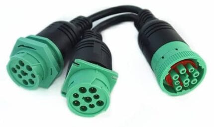
- Pre-2015 heavy trucks and tractors still in daily service, alongside our J1939 9-pin Y splitter cable for ELD and GPS trackers
- Coach and bus fleets with mixed build years, where one workshop has to serve both port types
- Diesel generator sets and stationary engines with a 9-pin service port
- Agricultural and construction machines where the port has never been upgraded, often paired with our DT06 to J1939 adapter cable for tractors and excavators
- Marine auxiliary engines and industrial diesels with a round diagnostic port
How to specify your build
- Port type — Type 1 (black) or Type 2 (green), confirmed from the port or the service manual.
- Pinout — your list, or a note that the commonly published assignment is what you want.
- Length, and whether the tool sits at the port or on a trolley.
- Jacket — PVC or TPU, and what it will be exposed to.
- Shielded or unshielded, where cost-sensitive programs can drop the braid.
- Quantity, and whether this is a prototype or a production order.
A photo of the existing port and the vehicle details is enough to start a quote.
Workmanship and testing
Each assembly is built and inspected to IPC/WHMA-A-620 Class 3 criteria within an ISO 9001 quality system, covering 32 to 12 AWG. Continuity and pinout are tested on every unit before packing. Where the specification calls for an ingress rating, seal checking on the batch can be quoted.
Custom builds and ordering
Five pieces is where a prototype starts and it ships in 3 working days. Production requires 500 pcs minimum and takes 14 working days after approval. Non-stock tooling adds around 10 working days. Private-label builds ship under your part number and labeling; material certificates and first-article reports are available on request.
Related diagnostic leads
- SAE J1939 OBD2 diagnostic cable, Type 2 green 9-pin to 16-pin adapter
- J1939 9-pin Y splitter cable for ELD and GPS trackers
- DT06 to J1939 adapter cable for tractors and excavators
- Heavy-duty 9-pin industrial diagnostic cable assembly
- Deutsch DT 6-pin heavy-duty diagnostic cable assembly
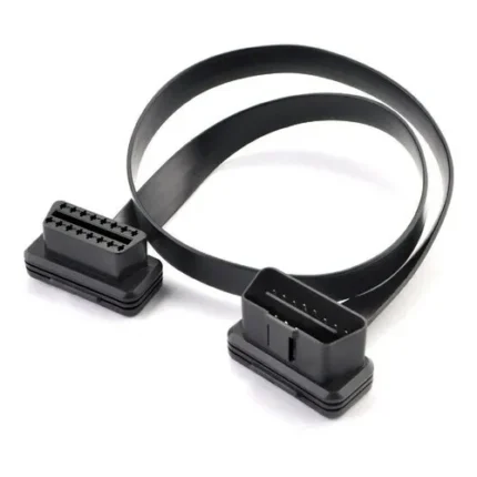
- OBD2 extension flat cable, 16-pin male to female ribbon lead
Full range: automotive cable and wire harness assemblies.
Frequently Asked Questions
Is this the same as a green Type 2 adapter?
No. The two shells are keyed differently and the two ports are not mechanically interchangeable. Black is Type 1, green is Type 2. If the color is faded, the keyway position identifies it.
Will it let a generic code reader talk to the engine?
If the vehicle puts J1939 on the CAN pair, yes. The adapter is passive, so it cannot create a bus that is not there, and it cannot convert a J1708 chassis to J1939.
Can you populate the manufacturer pins differently?
Yes. Send the pin list you want and we build to it. Where H and J are unused on your fleet we leave them unpopulated, which is the cheaper build.
Do you make the mating panel receptacle as well?
Yes. A 9-pin or 16-pin bulkhead with flying leads or a second connector on the back is a standard part of the build.
| Connector A | 9-pin round diagnostic plug, black shell, built to the Deutsch HD10 / HD16 series interface |
|---|---|
| Connector B | J1962 16-pin female socket |
| Wiring | CAN-H, CAN-L, battery and ground, wired passive |
| Conductor | Tinned copper, 20 to 18 AWG |
| Shielding | Foil plus braid, drain terminated at the shell |
| Jacket | Oil-resistant PVC or TPU |
| System voltage | 12 V / 24 V |
| Length | 0.3 m / 0.5 m / 1 m, custom on request |
| Function | Passive adapter, no protocol conversion |