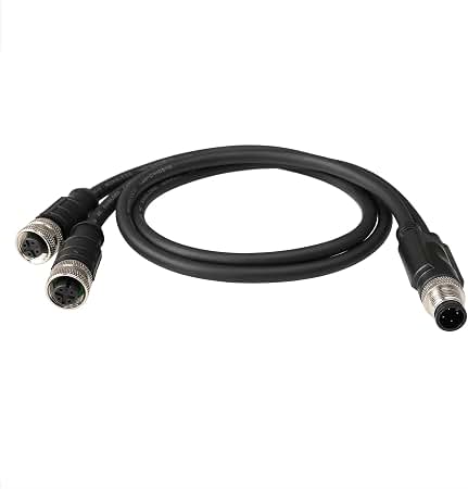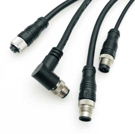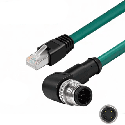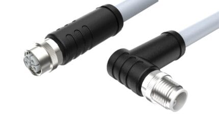
M12 Drag Chain Cable, Continuous Flex Cordset for Cable Carriers
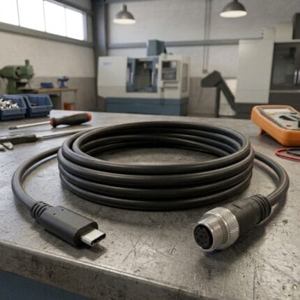
An M12 drag chain cable built around the carrier radius, travel length and cycle target your machine actually runs. Fine-strand high-flex copper, high-flex PUR jacket and a braid bonded to the coupling nut – send the motion data and we build to it.
Last updated: 13 September 2026
Overview
An M12 drag chain cable is specified around cycle life, not around current rating. In a carrier the copper work-hardens long before the jacket looks tired, so the usual failure is a conductor that has broken inside an intact outer sheath – which presents as an intermittent fault that no multimeter will find on a machine standing still. We build it around the carrier geometry you give us: radius, travel, speed and cycle target.
Key Specifications
| Coding | M12 A, B, C, D, X, S, K, T, L or P – to order |
|---|---|
| Pin count | 2 to 12 positions, per coding |
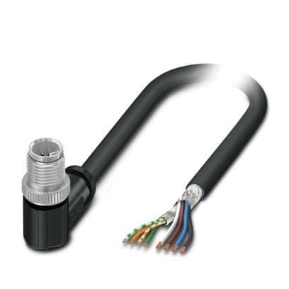
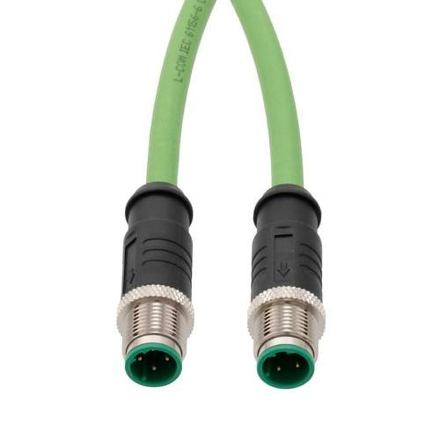
| Connector ends | M12 straight or right-angle, either end, or M12 to open leads |
| Conductor | Fine-strand high-flex copper, short equalised lay |
| Jacket | High-flex PUR for oil, coolant and carrier abrasion |
| Shielding | Braided overall screen bonded to the coupling nut |
| Bend radius | Set from the carrier radius you give us at quote stage |
| Motion | Continuous flex in carrier; torsion construction on request |
| Ingress rating | IP67 when mated – confirm per build |
Why fatigue, not overload, is what actually fails
Pull a failed drag-chain cordset apart and the overmold usually looks fine, the braid is intact and the jacket has no cut in it. The break is inside, at the point where the conductors flexed hardest – normally right where the cable leaves the strain relief. That is why the symptom is intermittent: the broken ends touch when the carrier is at rest and separate as it rolls over the bend. Oversizing the conductor helps a little; choosing the stranding, the lay length and the bend radius correctly helps a lot more.
Reading the carrier before you order
A cable that survives a 150 mm radius carrier will not survive a 60 mm one, whatever the jacket is made of. The table below is what we run through before quoting.
| What you tell us | What changes in the build |
|---|---|
| Carrier bend radius | Sets the minimum construction radius and the stranding class |
| Travel length and speed | Conductor size, and whether the run needs a support element |
| Cycle count target | Strand count and lay length |
| Motion type | Bending only, or torsion – different core layout and screen |
| What else is in the carrier | Jacket hardness and abrasion resistance |
Pinout reference for the two common drag-chain builds
Most continuous-flex M12 runs carry either a 4-pin sensor circuit or a 5-pin device with a spare. These are the wire colors most makers follow, not a guarantee – we terminate to the pinout you send, and on a moving cable the screen termination matters as much as the conductor order.
| Pin | Color | A-code 4-pin | A-code 5-pin | Note for flexing builds |
|---|---|---|---|---|
| 1 | Brown | +V (24 V DC) | +V (24 V DC) | Sized for the load, not for the signal |
| 2 | White | Signal 2 | Signal 2 | Keep paired with pin 4 where the signal is differential |
| 3 | Blue | 0 V | 0 V | Return |
| 4 | Black | Signal 1 | Signal 1 (IO-Link C/Q) | Switching output on most sensors |
| 5 | Gray | – | Functional earth or spare | Often taken as the shield drain |
| Shell | – | Braid | Braid | Bonded to the coupling nut at both ends |
Where a drag-chain build sits in the M12 coding family
Continuous flexing is a construction, not a coding – the same flex build can be put behind any keyway. What the coding decides is what travels down it. The M12 family below shares one 12 mm thread across every code, which is why the keyway is the only thing keeping a sensor lead out of a motor feed.
| Code | Positions | Carries | Typical use |
|---|---|---|---|
| A | 3 / 4 / 5 / 8 / 12 | DC sensor supply and signals, IO-Link | Proximity switches, photoelectric sensors, valve plugs |
| B | 5 | PROFIBUS-DP fieldbus | Legacy drives, remote I/O racks, weigh scales |
| C | 3 to 6 | AC power, dual keyway, extended earth | AC sensors, solenoid coils, legacy actuator blocks |
| D | 4 | 100 Mbit/s Ethernet over two pairs | PROFINET, EtherNet/IP, EtherCAT device drops |
| K | 4 + PE | Three-phase AC power | Motor feeds, power distribution blocks |
| L | 4 + PE | DC power | IO-Link power, AGV and drive supplies |
| M | 5 + PE | Three-phase motor plus brake pair | Servo and geared motors with holding brake |
| P | 4 + PE | Data pairs plus 24 V DC supply | Single-cable EtherCAT and remote I/O blocks |
| S | 3 + PE | Single-phase AC power | Field I/O blocks, cabinet heaters, pumps, fans |
| T | 4 | DC power, two circuits | Low-voltage DC distribution |
| X | 8 | Up to 10 Gbit/s Ethernet over four pairs | Machine vision, M12 to RJ45 10G links |
| Y | 6 + PE / 8 | Hybrid power plus Fast Ethernet | Valve islands, hybrid power and data drops |
A, B, C and D are the signal codings set out in IEC 61076-2-101; X is covered by IEC 61076-2-109 and the power codings by IEC 61076-2-111. Y is a de-facto hybrid arrangement used by several makers rather than an IEC-defined code. These are industry-standard descriptions of what each code is for – the values your assembly is built and verified to are the ones stated on your drawing.
Torsion is a different problem from bending
On a six-axis arm or a cobot wrist the cable is twisted as well as bent, and a construction that survives pure bending can fail quickly under torsion. If your application rotates, tell us the rotation angle per meter and the direction before the first article.
Jacket and screen inside a carrier
- High-flex PUR – the default for oil mist, coolant and abrasion against the separators. Ask for the high-flex grade; the difference shows at the million-cycle mark.
- Braid coverage – a screen that frets against itself as the cable flexes degrades long before the copper does. We specify coverage and bond the braid to the coupling nut so the screen path runs through the connector.
Typical applications for this M12 drag chain cable
- Cable carriers on gantries, pick-and-place units and machining centers
- Robot arms and cobot wrists, where the run also twists – see our torsion-resistant robot cable
- Moving camera and sensor mounts on packaging and filling lines
- Encoder and feedback runs on moving axes, alongside our encoder feedback cable with PUR jacket
- High-flex Ethernet in a carrier, using our Cat6A high-flex drag chain patch cord
What we need from you
- Carrier bend radius and travel length
- Cycle count target and speed
- Whether the motion is bending, torsion or both
- Coding, pin count and pinout
- Jacket exposure – oil, coolant, weld spatter, outdoor UV
- Length, and quantity for prototype versus production
Workmanship and testing
IPC/WHMA-A-620 Class 3 is the workmanship standard and ISO 9001 is the quality system behind it. We work from 32 to 12 AWG. Nothing ships without a continuity and pinout check, and seal checking can be added where an ingress rating is part of the specification.
Custom builds and ordering
Small runs start at 5 pcs and leave in 3 working days. At production volume the minimum is 500 pcs and lead time is 14 working days after approval. New tooling is about 10 working days on top. OEM and ODM orders ship under your part number, with material certificates and first-article reports available.
Related continuous-flex and M12 assemblies
- M12 A-coded straight or right-angle extension cable
- M12 12 pin cable for encoders and valve blocks
- M12 X-code Cat6A to RJ45 industrial Ethernet cable
- IP67 waterproof M12 molded cable
- M12 IP69K washdown cable with stainless steel coupling nut
- M12 D-code PROFINET industrial Ethernet cable
- Single Pair Ethernet cable in M8 and M12 shells
Full range: Circular M8 and M12 cable assemblies.
Frequently Asked Questions
How long will a drag chain cable last?
That depends on the carrier radius, the travel and the cycle target. Send those numbers and we will size the stranding to them and confirm the construction before the first article.
Can I have different connectors on each end?
Yes. M12 to M12, M12 to open leads, straight or right-angle in any combination, and any coding the device needs.
Is PUR always the right jacket for a carrier?
For oil, coolant and abrasion, yes in most cells. Where the carrier is dry, PVC is still workable and we will say so.
Do you build torsion versions?
Yes. Tell us the rotation angle per meter and the direction at quote stage, because the construction is different from a pure-bending build.
| Conductor | Fine-strand high-flex copper, short equalised lay |
|---|---|
| Jacket | High-flex PUR for oil, coolant and carrier abrasion |
| Motion | Continuous flex in carrier; torsion construction on request |
| Bend radius | Set from the carrier radius you give us at quote stage |
| Shielding | Braided overall screen bonded to the coupling nut |
| Ingress rating | IP67 when mated – confirm per build |
| Coding | M12 A, B, C, D, X, S, K, T, L or P – to order |
| Pin count | 2 to 12 positions, per coding |
| Connector ends | M12 straight or right-angle, either end, or M12 to open leads |