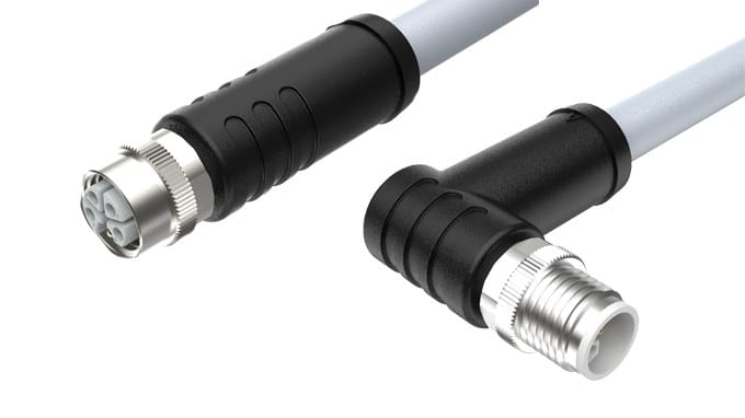
M12 L-Code Power Splitter for Two IO-Link Masters
An M12 L-code power splitter turns one incoming 24 V feed into two L-coded outlets, so two IO-Link masters or field modules share a single home run. Molded branch, panel-mount or free-hanging, sized to your loads.
Overview
A splitter is a wiring decision turned into a part. An M12 L-code power splitter takes one incoming feed and breaks it into two L-coded outlets, so two IO-Link masters or two field modules can hang off a single home run. It removes one cable from the tray and one pair of terminals from the cabinet, and it shortens fault finding because the branch point is visible on the machine instead of buried inside a junction box.
Key Specifications
| Inlet | 1 x M12 L-coded male, 5 positions (4 + FE) |
|---|---|
| Outlets | 2 x M12 L-coded female |
| Total current | 16 A (pending supplier datasheet) |
| Per-branch current | 12 A (pending supplier datasheet) |
| Ingress rating | IP67 (pending supplier test report) |
| Body material | PUR overmolded |
| Options | LED power indicator, panel-mount housing, free-hanging body |
| Construction | Molded branch, no field terminations |
| Mounting | Panel-mount or strap-fixed to machine frame |
| Sizing note | Voltage drop over feed and branch to be calculated per installation |
What it replaces
The usual alternatives are a junction box with terminal blocks, or two separate home runs back to the cabinet. An overmolded splitter does the same job in a body that fits in the palm of a hand, and because the branch is molded rather than terminated on site there are no screws to work loose over time.
Inlet to outlet pin map
All five positions pass straight through to both outlets, so the branch does not change the meaning of a pin.
| Inlet pin | Function | Outlet A | Outlet B |
|---|---|---|---|
| 1 | +24 V DC | 1 – +24 V DC | 1 – +24 V DC |
| 2 | 0 V | 2 – 0 V | 2 – 0 V |
| 3 | 0 V | 3 – 0 V | 3 – 0 V |
| 4 | +24 V DC | 4 – +24 V DC | 4 – +24 V DC |
| 5 | FE | 5 – FE | 5 – FE |
The current budget across two branches
This is where a splitter differs from a plain cordset. A cordset has one current rating; a splitter has three, and only one of them belongs to the connector.
| Part of the run | What limits it | What we need from you |
|---|---|---|
| Feed into the inlet | Conductor size feeding the splitter and ambient temperature | Feed length and the supply cross-section |
| The splitter body | Total through-current of the molded branch | Total load on both outlets |
| Each branch | Per-branch rating and the branch conductor size | Load on each outlet and branch length |
| The load itself | Voltage actually arriving after the drop | Minimum voltage the module needs |
Published figures for comparable parts put the total current at 16 A with each branch limited to 12 A, but those are competitor values, and they depend entirely on the conductor size feeding the splitter and on the ambient temperature at the point of installation. Your assembly is manufactured and accepted to the nominal values on your drawing.
Protecting both branches
A splitter does not protect anything by itself, and that is worth saying plainly: overcurrent protection belongs to the supply feeding it. What we can do is make the branches honest. Each branch conductor is sized for the load you tell us about, and the branch lengths can be different if the two modules sit at different distances. If one branch draws a lot more than the other, say so – the branch that carries more should get the larger conductor, and a symmetric build is not automatically the right one.
The coding family, read for a splitter
Splitters exist mainly in the power codings, and the keyway is what stops a DC distribution body being plugged into a mains outlet.
| Code | Contacts | Carries | Voltage class | Note for splitters |
|---|---|---|---|---|
| L | 4+FE | DC power | 63 V DC | The usual coding for a 24 V DC splitter |
| T | 2 to 4 | DC power | 63 V DC | Also used for DC distribution bodies |
| K | 4+PE | Three-phase AC | 630 V AC | Never interchangeable with L |
| S | 2+PE / 3+PE | Single-phase AC | 630 V AC | Never interchangeable with L |
| M | 5 to 6 | Servo power with brake | 630 V AC | Not used for splitters |
| A | 3 to 12 | Sensor signals | 30-250 V | Sensor splitters use A-code, not L |
| C | 3 to 6 | AC power | 250 V AC | Legacy AC distribution |
| D | 4 | 100 Mbit/s Ethernet | 60 V | Data splitters are not simple Y bodies |
| X | 8 | 10 Gbit/s Ethernet | 60 V DC | Not split this way |
| B | 4 to 5 | PROFIBUS-DP | 60 V | Bus topology, not a Y branch |
| P | 4 | EtherCAT P | 60 V | Purpose-built, not a passive Y |
| Y | 8 (4+4) | Power plus Fast Ethernet | 50 V | Hybrid, check the pinout first |
A distribution block only makes sense in one coding, and the keyway is what enforces it. The download center carries a two-page reference covering every M12 letter from A to Y with pole counts and typical duties.
Sizing the run
Voltage drop over the feed is usually the binding constraint rather than the connector rating. A branch rated for 12 A tells you nothing about the voltage actually arriving at the load if the feed is thirty meters of undersized copper, and voltage drop is a property of the whole path, not of the splitter. Send us the load current on each branch, the length of the feed and of each branch, and the ambient temperature, and we will size the conductor on both sides of the splitter and return the calculation with the quotation.
Build options
- One L-coded male inlet to two L-coded female outlets
- PUR overmolded body for washdown, oil and coolant exposure
- Version with an LED power indicator visible on the body
- Panel-mount housing or free-hanging body with fixing holes
Before you order
Tell us the mating receptacles already on your masters or modules so we can confirm coding and pinout before production. An L-coded splitter is keyed so it cannot be mated into a mains-voltage K-coded or S-coded outlet, but it is worth checking the codings actually fitted on site.
Typical applications for this M12 L-code power splitter
- Two IO-Link masters fed from one home run at the end of a machine
- A field I/O island and a valve block sharing a single 24 V feed
- Pairs of compact drives on a conveyor module
- Retrofit work where a second home run is impractical to pull
How to specify your build
- Inlet and outlet coding, and the receptacles already on site.
- Load on each branch, and the branch lengths.
- Feed length and cross-section.
- Mounting – panel-mount or free-hanging.
- Options – LED indicator, outlet orientation.
- Quantity, prototype or production.
Workmanship and testing
IPC/WHMA-A-620 Class 3 is the workmanship bar for M12 L-Code Power builds, and ISO 9001 is the system behind the line, from 32 to 12 AWG. Every M12 build gets a continuity and pinout check before it is boxed, and seal checking is quoted whenever an ingress rating is on the drawing.
Every production run can ship with RoHS and REACH declarations and the electrical report agreed at quotation; see certifications and material declarations. UL styles and other named approvals are built to drawing: we source to the style you specify and document it, rather than asserting a listing we do not hold. Where this build needs an overmold, the tool is designed, cut and maintained in our own shop under in-house mold making and overmold tooling, and it is never used for another customer’s program. More background: cable assemblies for industrial automation and robotics.
Custom builds and ordering
Five pieces is the prototype minimum for M12 L-Code Power builds, shipping in 3 working days; the production minimum is 500 pcs, delivered 14 working days after approval. Tooling not already held adds around 10 working days. M12 orders ship as OEM or ODM under your part number and labeling material certificates plus first-article reports are available.
Related M12 power assemblies
- M12 L-Code 16A Cable for IO-Link Power and AGV Drives
- M12 Power T-Code or L-Code DC Power Cable, 63 V DC
- M12 IO-Link Cable, Master to Device Drop for 3 and 4 Wire Ports
- M12 A-Code 4-Pin Y-Splitter Sensor / Actuator Cable
- M12 K-Coded Power Cable for 630 V AC Motor Feeds
- M12 Bulkhead Panel Connector with Pigtail, A, D and X Coding
- 7/8″ 5-Pin T-Splitter, 1 Male to 2 Female, IP67
Full range: circular M8 and M12 cable assemblies.
Frequently Asked Questions
Does the splitter protect each branch?
No. Overcurrent protection belongs to the supply feeding it. What we do is size each branch conductor for the load you specify, and add an LED indicator if you want a visible supply.
Can the two branches be different lengths?
Yes, and they often should be. Tell us where each module sits and we will build asymmetric branch lengths.
How much current can each outlet take?
Comparable parts quote 16 A total with 12 A per branch, but those figures depend on the feeding conductor and the ambient temperature. Send us the duty and we will confirm the real numbers.
| Inlet | 1 x M12 L-coded male, 5 positions (4 + FE) |
|---|---|
| Outlets | 2 x M12 L-coded female |
| Total current | 16 A class |
| Per-branch current | 12 A class |
| Ingress rating | Stated per your drawing |
| Body material | PUR overmolded |
| Options | LED power indicator, panel-mount housing, free-hanging body |
| Construction | Molded branch, no field terminations |
| Mounting | Panel-mount or strap-fixed to machine frame |
| Sizing note | Voltage drop over feed and branch to be calculated per installation |