Robot Torsion Resistant Cable for Six-Axis Arm Wiring
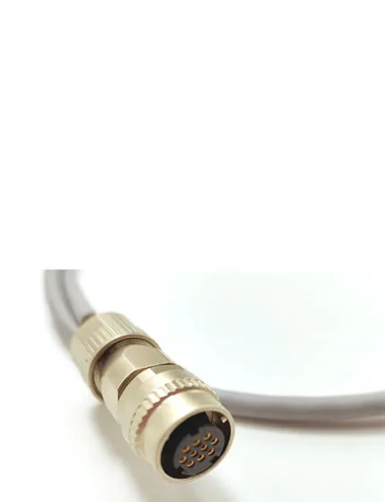
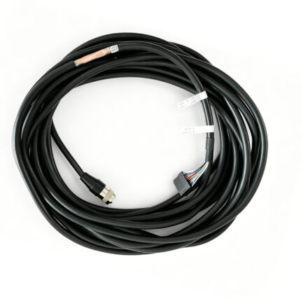
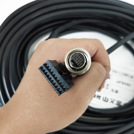
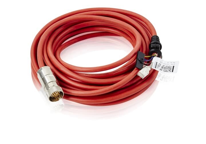
A robot torsion resistant cable built for the twist load case rather than a pure bend cycle. 2 to 60 cores with mixed cross-sections in one sheath, foil and braid shielding applied per functional group, overmolded M23, M40 or Han style inserts. Built to your axis travel.
Last updated: 13 September 2026
Overview
A six-axis robot does not simply flex its harness, it twists it. Every rotation of axis 1 and axis 6 puts the bundle through a controlled twist, and a cable specified only for bending fails there first: cores bunch, shields fracture, and the conductor lay opens up until the link goes intermittent. This robot torsion resistant cable range is built around that load case rather than around a catalog bend cycle.
Key Specifications
| Product type | Torsion-resistant robot body cable |
|---|---|
| Conductor count | 2 to 60 cores, mixed cross-sections |
| Torsion grade | Plus/minus 180 deg or 360 deg per meter by grade – to be confirmed |
| Drag-chain life | Stated as a design target only, pending cycle test |
| Jacket material | PUR, with a TPE option |
| Temperature range | -40 to +90 degrees C – to be confirmed |
| Shielding | Foil and braid applied per functional group |
| Connector options | Overmolded M23 / M40 / Han style inserts, or open ends |
Torsion versus bending: what actually breaks
The two load cases do not damage a cable the same way, which is why a high bend cycle rating tells you nothing about how the harness will survive axis 6. In a bend cycle the neutral axis stays put and fatigue concentrates where the cable leaves the clamp. Under torsion the whole cross-section rotates relative to itself:
| Mechanism | What you see on the failed cable | Build answer |
|---|---|---|
| Cores bunching toward the center | Inner conductors compressed, outer ones stretched and necked | Lay length and core grouping set together for the twist angle |
| Shield fracture | Braid opens in a spiral, screening fails before any conductor does | Foil plus braid per group, braid angle set for the twist |
| Lay opening up | Intermittent faults that move with the arm position | Stranding and fillers chosen to hold the core bundle in place |
| Jacket wear against the dresspack | Abraded sheath, then coolant ingress into the core bundle | PUR jacket, TPE where oil or coolant exposure is higher |
Conductor lay and group shielding
Stranding, lay length and core grouping are specified together so that power pairs, signal pairs and bus pairs can share one sheath without the bus pair picking up switching noise from the drive conductors. Shielding is applied per functional group instead of as one overall braid, which keeps the encoder or fieldbus return path clean while the motor conductors switch. Core count runs from 2 to 60 conductors with mixed cross-sections in a single sheath, so a whole arm can be wired with one part number.
Jacket, temperature and the dresspack
PUR is the default for oil and coolant contact and for the abrasion a harness sees against its own dresspack. TPE is the option where higher oil or coolant resistance is needed, or where the run sees both low temperature and continuous movement. The quoted operating window of -40 to +90 degrees C, the drag-chain cycle count and the torsion grade of plus or minus 180 or 360 degrees per meter are all treated as targets until our own test rig results are in; nothing goes onto a printed datasheet that we cannot reproduce.
Where the harness runs
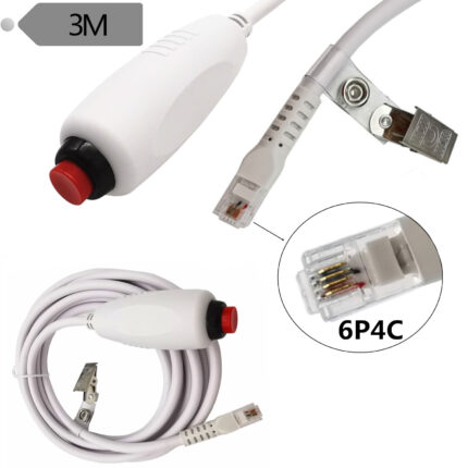
Typical routes are base to axis 3, axis 3 to the wrist, and cabinet to robot base where the harness runs through fixed conduit and then into a moving dresspack. Teach pendant leads and encoder links on the same arm are normally separate, smaller assemblies, so a damaged pendant lead can be swapped without re-pulling the power bundle. If the arm works in a classified or vacuum environment, that changes the material set entirely – our cleanroom robot cable harness covers that case.
How to specify
- Axis travel, and the twist angle per meter at the worst point in the route.
- Core mix – how many power, signal and bus elements, and their cross-sections.
- Fixed or dresspack, and whether the run also sees a drag chain.
- Environment – oil, coolant, welding spark, temperature.
- Termination – overmolded M23, M40 or Han style inserts, or open ends for field assembly.
- Length per section, measured on the installed route.
Typical applications for this robot torsion resistant cable
- Axis 1 and axis 6 harness sections on six-axis welding and handling arms
- Full arm dresspacks built alongside our hybrid robot torsion cable where data pairs are needed
- Cabinet to base runs that pass through conduit into a moving section, with our robot teach pendant cable kept as a separate assembly
- Cobot and small arm installations using a cobot arm cable harness with drag-chain jacket
- Motor and feedback drops terminated in M23 screw lock cable assemblies
Workmanship and testing
The line works to IPC/WHMA-A-620 Class 3 under ISO 9001, terminating 32 to 12 AWG. Every unit gets a continuity and pinout test before it is packed. Seal checking on the production batch is available when an ingress rating is in the specification.
Custom builds and ordering
Prototype quantity starts at 5 pcs with a 3 working day turnaround, and production starts at MOQ 500 pcs shipping 14 working days after approval. Where a new tool is needed, allow about 10 working days. We ship OEM and ODM builds under your part number and labeling, and can provide material certificates and first-article reports.
Related assemblies
- Hybrid Robot Torsion Cable with CAT6 Data Pair, Power and Control Cores
- Robot Teach Pendant Cable with PUR Jacket for Arm Controllers
- Cleanroom Robot Cable Harness for EFEM and Vacuum Transfer Arms
- Custom Industrial Robot Wire Harness
- M23 Screw Lock Cable for Servo Motor Power and Encoder Feedback
- Cobot Arm Cable Harness with Drag-Chain Jacket
Full range: custom wire harnesses.
Frequently Asked Questions
My cable has a high bend cycle rating but fails at axis 6. Why?
Bend and twist are different load cases. A bend rating says nothing about what happens when the whole cross-section rotates relative to itself, which is what axis 1 and axis 6 do every cycle.
How many cores can go in one sheath?
From 2 to 60, with mixed cross-sections. Grouping and lay length are set against the twist angle rather than taken from a catalog.
Can you terminate the arm end?
Yes. Overmolded M23, M40 or Han style inserts, or open ends if your team terminates on site.
What is the minimum order?
5 pcs minimum for prototypes, shipping in 3 working days. Production runs of 500 pcs and up ship 14 working days after approval.
| Product type | Torsion-resistant robot body cable |
|---|---|
| Conductor count | 2 to 60 cores, mixed cross-sections |
| Torsion grade | Plus/minus 180 deg or 360 deg per meter by grade – to be confirmed |
| Drag-chain life | Stated as a design target only |
| Jacket material | PUR, TPE option |
| Temperature range | -40 to +90 degrees C – to be confirmed |
| Shielding | Foil and braid applied per functional group |
| Connector options | Overmolded M23 / M40 / Han style inserts, or open ends |