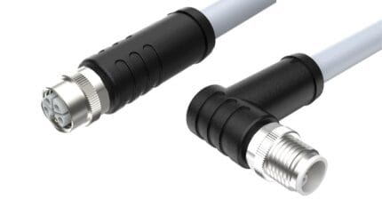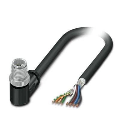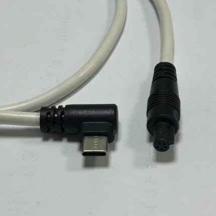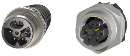
Single Pair Ethernet Cable in M8 and M12 Shells for Sensor Runs
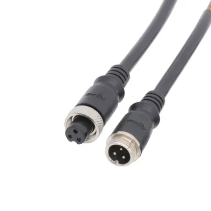
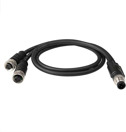
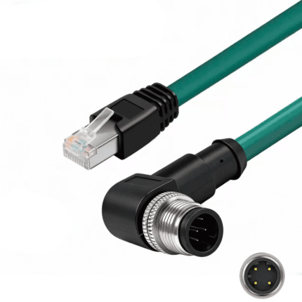
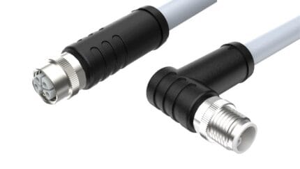
A single pair Ethernet cable runs IP over two conductors instead of four pairs, in M8 or M12 shells to IEC 63171-5 and -7. Thinner, lighter, longer reaching, and PoDL capable. Built to your length and pinout.
Overview
A single pair Ethernet cable carries Ethernet over two conductors instead of four pairs. That is the whole idea, and everything else follows from it: smaller connectors, thinner cable, longer reach at low speed, and a routed network that reaches the devices at the edge of a plant or a building instead of stopping at the nearest fieldbus coupler. We build it in M8 and M12 shells, to the mating face you specify.
Key Specifications
| Interface | Single pair ethernet, 2 conductors |
|---|---|
| Shells offered | M8 and M12 |
| Mating face standards | IEC 63171-5 for IP67 industrial variants, IEC 63171-7 for hybrid (confirm applicable edition) |
| Data rate | Gigabit over short runs, 10 Mbps over long runs (pending supplier datasheet) |
| Reach | up to 1000 m at 10 Mbps quoted in competitor data, pending confirmation |
| Power over data line | PoDL, 50 to 52 W class quoted in competitor data, pending confirmation |
| Conductor cross-section | 0.34 to 2 mm2 depending on variant (pending supplier datasheet) |
| Jacket material | Halogen-free PUR, green or black |
| Temperature range | -40 to +85 C class (pending supplier datasheet) |
| Ingress rating | IP65 / IP67 class (pending supplier test report) |
| Standard lengths | 1 / 2 / 5 / 10 / 25 m |
Why two wires instead of eight
Industrial Ethernet was designed for bandwidth, and a proximity switch does not need any. For thirty years the gap between a sensor and the network was filled by a 4-20 mA current loop or an RS-485 drop, both of which require a gateway, a separate topology and a person who understands them. Single pair Ethernet removes the gateway: the device speaks IP, the switch speaks IP, and the cable in between is two conductors in a shield. In a plant with thousands of discrete points, that changes the cost of the last hundred meters.
Choosing an M8 or an M12 shell
Both shells appear in the IEC 63171 series, and the choice is usually made for you by the device and by what the installation team already stocks.
| Shell | Mating face | Where it wins | Watch out for |
|---|---|---|---|
| M8 | IEC 63171-5 class | Smallest sensors and the tightest sensor heads | Bend radius behind the device |
| M8 hybrid | IEC 63171-7 class | A sensor that needs more power than one pair carries | Supplier specific pinout |
| M12 | IEC 63171-5 class | Installations that already stock M12 tooling and glands | Do not confuse with A-coded sensor ports |
| M12 hybrid | IEC 63171-7 class | Valve islands and actuators on one connector | Power class has to match the device |
The IP67 industrial variants of the mating face are covered by IEC 63171-5, and the hybrid face that puts power contacts beside the pair is covered by IEC 63171-7. Confirm the applicable edition, because the series has been extended more than once.
Reach, speed and 10BASE-T1L
The trade is speed against distance. Short runs can carry gigabit; the same cable at 10 Mbps reaches into the hundreds of meters, and competitor data quotes up to 1000 m at that rate. That long-reach, low-speed mode is the one usually meant when people cite 10BASE-T1L, defined in IEEE 802.3cg: it is what makes a sensor at the far end of a plant a network device rather than a current loop. Power over the data line is the other reason the technology is being adopted at device level, and Power over Ethernet is the nearest concept most engineers already know, except that here the supply rides on the same two conductors as the data. The quoted figures, including a 600 MHz bandwidth claim and a 50 to 52 W power class, come from competitor literature and need supplier confirmation before they appear on our datasheet.
The M12 coding family, and where SPE sits in it
Single pair Ethernet uses its own mating faces rather than the classic coding letters, but on a real machine they live side by side, so this is the map.
| Code or face | Contacts | Carries | Voltage class | Relevance to SPE |
|---|---|---|---|---|
| A | 3 to 12 | Sensor signals, IO-Link | 30-250 V | The port SPE replaces on new builds |
| D | 4 | 100 Mbit/s Ethernet | 60 V | The four-pair alternative |
| X | 8 | 10 Gbit/s Ethernet | 60 V DC | For vision, not for sensor drops |
| IEC 63171-5 M8 | 2 | Single pair Ethernet | Device dependent | Smallest SPE shells |
| IEC 63171-5 M12 | 2 | Single pair Ethernet | Device dependent | Standard SPE in M12 tooling |
| IEC 63171-7 hybrid | 4 to 6 | SPE plus power | Device dependent | Where the load outgrows PoDL |
| B | 4 to 5 | PROFIBUS-DP | 60 V | Legacy fieldbus being migrated |
| C | 3 to 6 | AC power | 250 V AC | Older AC auxiliary circuits |
| M | 5 to 6 | Servo power with brake | 630 V AC | Motion axes |
| P | 4 | EtherCAT P | 60 V | Bus with power on the same cable |
| L | 4+FE | DC power | 63 V DC | Power when you do not use PoDL |
| T | 2 to 4 | DC power | 63 V DC | DC distribution |
| K | 4+PE | Three-phase AC | 630 V AC | Motor feeds |
| S | 2+PE / 3+PE | Single-phase AC | 630 V AC | Mains distribution |
| Y | 8 (4+4) | Power plus Fast Ethernet | 50 V | Two-pair hybrid alternative |
SPE uses its own interface rather than a code letter, so most of the planning is about what else shares the panel. Our download center has a two-page M12 coding reference covering A through Y for exactly that comparison.
Migration, not replacement
Almost nobody replaces a working 4-20 mA installation for the pleasure of it. The usual path is a new machine or a new line where the sensors are specified as SPE from the start, with a gateway where the new segment has to talk to the old network. That is worth planning: the coding, the pinout and the power class have to match on both ends, and the cable you choose should be the one the gateway vendor tested against.
What needs confirming
These figures are taken from published competitor data, not from a verified datasheet for our part. Ask for the supplier document behind it.
Typical applications for this single pair ethernet cable
- Long sensor runs where four-pair Ethernet would need a repeater
- Building management device drops that replace a current loop
- Compact sensors in M8 shells where panel space is the constraint
- Process instrumentation on a new line specified as SPE from the start
How to specify your build
- Shell – M8 or M12, data only or hybrid.
- Mating face – IEC 63171-5 or -7, and the edition.
- Speed and reach you actually need.
- Power class, if the device is PoDL fed.
- Length, jacket color and ingress rating.
- Quantity, prototype or production.
Workmanship and testing
Terminations on Single Pair Ethernet builds run from 32 to 12 AWG, and the work is held to IPC/WHMA-A-620 Class 3 inside an ISO 9001 system. 100% continuity and pinout are checked on every Single unit before packing, and seal checking is quoted whenever an ingress rating is on the drawing.
Every production run can ship with RoHS and REACH declarations and the electrical report agreed at quotation; see certifications and material declarations. UL styles and other named approvals are built to drawing: we source to the style you specify and document it, rather than asserting a listing we do not hold. This assembly is built on the four lines covered under our assembly lines in Longgang, with nothing in the build handed to an undisclosed subcontractor. More background: our industrial automation work. Tooling is quoted separately, cut in-house rather than brokered out, and owned by you.
Custom builds and ordering
Single Pair Ethernet prototypes start from 1 to 50 pcs and ship in 3 working days; series supply starts at 500 pcs and takes 14 working days after sample sign-off. Tooling not already held adds around 10 working days. Single builds ship under your part number and labeling for OEM and ODM orders, and material certificates plus first-article reports are available.
Related SPE and sensor assemblies
- SPE M12 Hybrid Single-Pair Ethernet + Power Cable (IEC 63171-7)
- M12 Hybrid SPE Cable for Actuators and Valve Islands
- SPE Bulkhead Panel Connector for 10BASE-T1L Field Devices
- M8 3-Pin A-Coded Circular Connector Sensor / Actuator Cable
- M8 6-Pin A-Coded Sensor Cable, Straight Male to Female
- M12 IO-Link Cable, Master to Device Drop for 3 and 4 Wire Ports
Full range: circular M8 and M12 cable assemblies.
Frequently Asked Questions
What is the difference between IEC 63171-5 and -7?
The -5 series covers the IP67 industrial single pair mating faces, including the M8 and M12 shells. The -7 series covers the hybrid face that puts power contacts alongside the pair.
How far can it run?
Competitor data quotes up to 1000 m at 10 Mbps. Reach falls as the speed rises, so tell us the rate you need and we will confirm the distance against the supplier document.
Can the pair also carry power?
Yes, via PoDL, up to the power class the device and the power sourcing equipment agree on. Published classes need supplier confirmation before we quote them.
| Interface | Single pair ethernet, 2 conductors |
|---|---|
| Shells offered | M8 and M12 |
| Mating face standards | IEC 63171-5 for IP67 industrial variants, IEC 63171-7 for hybrid (confirm applicable edition) |
| Data rate | Gigabit over short runs, 10 Mbps over long runs class |
| Reach | up to 1000 m at 10 Mbps class |
| Power over data line | Stated per your drawing |
| Conductor cross-section | 0.34 to 2 mm2 depending on variant |
| Jacket material | Halogen-free PUR, green or black |
| Temperature range | -40 to +85 C class |
| Ingress rating | IP65 / IP67 class |
| Standard lengths | 1 / 2 / 5 / 10 / 25 m |