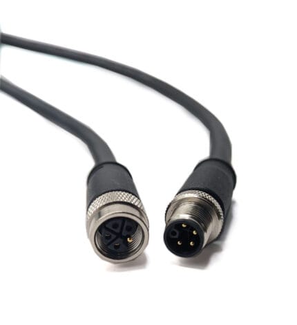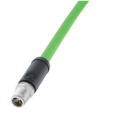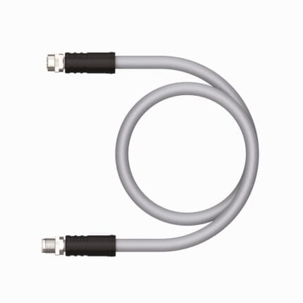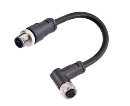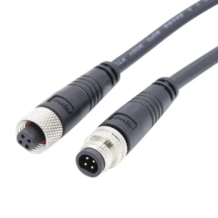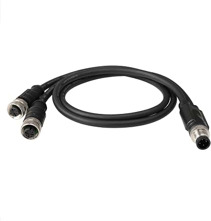
M12 A-Code 4-Pin Y-Splitter Sensor / Actuator Cable
This M12 y splitter sensor cable turns one four-position A-coded port into two, so one home run feeds two sensors or actuators. IEC 61076-2-101, IP67 molded Y block, 4 A / 60 V DC, PVC or PUR. Size the trunk for both loads.
Overview
An M12 Y splitter sensor cable takes one four-position port on a controller or a distribution block and turns it into two. The arithmetic is appealing: one socket becomes two devices, one cable replaces two, and the device count per cabinet doubles without a second home run. The engineering caution is shared current and shared diagnostics, because everything downstream of the split now arrives at the input card as one electrical circuit. Used where that is fine, it is a cheap win. Used where it is not, it creates faults nobody can isolate.
Key Specifications
| Connector A | M12 A-coded 4-pin male, screw lock, IP67 |
|---|---|
| Connector B | 2 x M12 A-coded 4-pin female, screw lock, IP67 |
| Coding | A per IEC 61076-2-101 |
| Pin count | 4-pin (3 plus PE style assignment) |
| Rated | 4 A / 60 V DC |
| Conductor | 4 x 22 AWG class, per branch and trunk |
| Jacket | PVC or PUR, black, drag chain capable on request |
| Splice body | Injection molded Y block under TPE overmold |
| Length | OEM build to required length |
What the Y actually shares
Two branch cables and one trunk, and every conductor in the trunk carries the sum of what the two branches draw. Nothing about the split is electrically isolated; a Y splitter is a wiring device, not a distribution device.
| Shared item | Consequence | Check before ordering |
|---|---|---|
| Supply conductors | Trunk carries the combined current of both devices | Sum both loads and any inrush |
| The switched output | Two outputs land on one input and read as one state | Whether the input can tolerate a combined signal |
| Diagnostics | A fault on either branch looks identical at the card | Whether per-channel diagnostics are required |
| The single port | One failed branch takes down both device feeds if wired as a loop | The wiring topology at the device end |
Build the current budget first
The classic failure is not dramatic. Two devices each drawing a little under their share work individually, and together they pull the trunk past what the contact pair wants to carry continuously, particularly in a warm tray alongside other conductors.
| Question | Why it decides the build | Answer source |
|---|---|---|
| Steady current of each device | Both sum in the trunk conductors | Stated per your drawing |
| Inrush when both switch on together | Two simultaneous inrush events are common after a stop | Device datasheet |
| Ambient temperature at the trunk | Derating is cumulative across the shared path | Confirm at order |
| Length of trunk and branches | Voltage drop usually bites before current does | Stated per your drawing |
| Jacket and duty | Oil, coolant or flexing changes the material | Confirm at order |
Where the answer comes back uncomfortable, split the loads onto separate conductors rather than pushing shared ones harder. An L-coded power splitter is the right tool when the demand is genuinely power rather than signal.
Where a Y splitter is the wrong answer
Four situations, and all of them get discovered during commissioning rather than on the drawing.
| Situation | What goes wrong | Do this instead |
|---|---|---|
| Analog 4-20 mA loops sharing a return | Return currents add and the measurement lies | Individual shielded runs per transmitter |
| Devices needing individual diagnostics | One input cannot tell you which branch failed | Separate channels on the I/O card |
| Shielded or high speed signals | A splice breaks the screen geometry and the impedance budget | One cable per device |
| Two loads with independent control | Switching one affects both through the shared trunk | Two outputs from the controller |
The pin assignment, as built
Each branch carries the same four-position A-coded layout, so existing cordsets plug in unchanged. This is the assignment used for the standard build; if your devices use another, send it and we will terminate to yours.
| Pin | Wire color | Function | Note |
|---|---|---|---|
| 1 | Brown | Power positive | Typically 24 V DC on the trunk |
| 2 | White | Signal | Second output or control conductor, device dependent |
| 3 | Blue | Power negative | Common return shared across branches |
| 4 | Black | Signal | Switched output of the device on that branch |
The splice itself is injection molded and sits inside a TPE overmold, which keeps the junction sealed to the same mated rating as the rest of the assembly. Strain relief on all three legs matters more here than on a straight cordset, because the Y block is the point where the installers hand lands.
A splitter inherits the coding of the body it is built on, which is why a Y in the wrong keyway is a whole assembly to redo. The download center carries a two-page coding reference covering every M12 letter and the pole counts each normally uses.
Typical applications for this M12 Y splitter sensor cable
- Feeding two proximity or photoelectric sensors from one distributed I/O port
- Splitting one controller output to two solenoid coils on a valve manifold
- Doubling device density in a machine cell without running a second trunk back to the cabinet
- Sensor hubs and local junction blocks where devices share one physical location
- Conveyor modules with two limit switches reporting to one counting input
How to specify your build
- Trunk connector and each branch connector, male or female.
- Trunk length and branch lengths, measured separately.
- Load per branch, including inrush.
- Jacket – PVC indoors, PUR where coolant or flexing is present.
- Pin assignment, if it departs from the table above.
- Quantity, prototype or production.
Workmanship and testing
Terminations on M12 A-Code 4-Pin Y-Splitter builds run from 32 to 12 AWG, and the work is held to IPC/WHMA-A-620 Class 3 inside an ISO 9001 system. continuity and pinout are checked on every M12 unit before packing, and seal checking is quoted whenever an ingress rating is on the drawing.
Material declarations against RoHS and REACH are issued per project, alongside the dimensional and electrical reports agreed at quotation; see certifications, compliance and material declarations. Where your drawing names a UL style or another approval, the build follows your drawing and ships with the supporting document rather than a claim of our own. For continuous motion the stranding, lay length and jacket are built to the flex method described under continuous-flex construction and flex-life testing, with the cycle count defined in the test scope. More background: what automation programs ask for. Tooling for this build is cut in our own tool room and belongs to your program, so a repeat run years later starts from the same tool.
Custom builds and ordering
M12 A-Code 4-Pin Y-Splitter prototypes start from 1 to 50 pcs and ship in 3 working days; series supply starts at 500 pcs and takes 14 working days after sample sign-off. Tooling not already held adds around 10 working days. M12 builds ship under your part number and labeling for OEM and ODM orders, and material certificates with first-article reports are available.
Related M8 and M12 assemblies
- M12 IO-Link Cable, Master to Device Drop
- M12 L-Code Power Splitter for Two IO-Link Masters
- M12 3-Pin A-Coded Sensor / Actuator Extension Cable
- M12 12-Pin Bulkhead Cable with Flying Leads
- M12 Hybrid SPE Cable for Actuators and Valve Islands
- M12 A-Coded PVC/PUR Straight or Right-Angle Extension Cable
- 7/8″ 5-Pin T-Splitter, 1 Male to 2 Female, IP67
Full range: circular M8 and M12 cable assemblies.
Frequently Asked Questions
Do both branches carry full current?
Each branch does, and the trunk carries their sum. Size the trunk against the combined load plus any simultaneous inrush.
Can I use this for analog signals?
Generally not. Shared returns corrupt a 4-20 mA loop, so run separate shielded cables per transmitter.
Will the card tell me which branch failed?
No. Everything downstream of the split appears as one circuit, so per-channel diagnostics are not possible through a Y.
Is the splice sealed?
Yes, it is molded and sits under a TPE overmold so the junction matches the mated rating of the rest of the assembly.
Can the two branches be different lengths?
Yes, and that is common. Give us the trunk length and each branch length separately.
| Connector A | M12 A-coded 4-pin male, screw lock, IP67 |
|---|---|
| Connector B | 2 x M12 A-coded 4-pin female, screw lock, IP67 |
| Coding | A per IEC 61076-2-101 |
| Pin Count | 4-pin (3 + PE) |
| Rated | 4 A / 60 V DC |
| Jacket | PVC or PUR, black, drag-chain rated on request |
| Length | OEM build to required length |
| Conductor | 4 x 22 AWG class, trunk and branches |