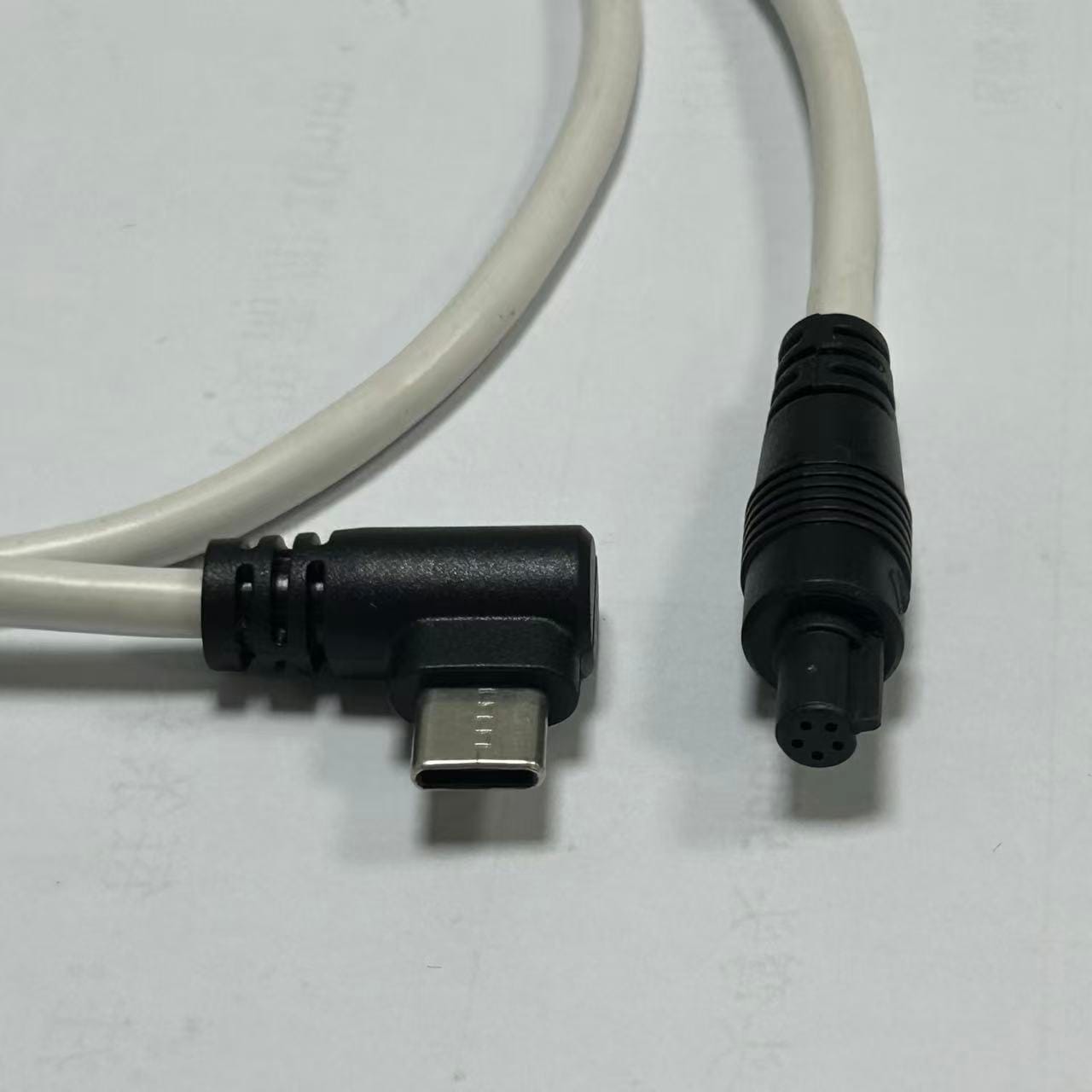
M8 5-Pin to USB Type-C Adapter Cable
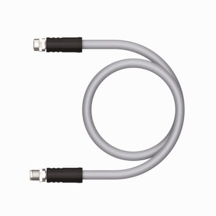
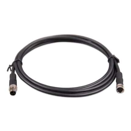
This M8 5 pin adapter cable takes a sealed five-position A-coded port to USB Type-C for configuration laptops and diagnostic logging. IP67 on the M8 end, 5 x 28 AWG, TPU or PVC jacket. Confirm what protocol arrives on the pins before ordering.
Overview
An M8 5 pin adapter cable exists because commissioning always needs a laptop, and laptops stopped shipping industrial connectors about two decades ago. One end is a sealed A-coded M8 interface that stays IP67 when mated; the other is USB Type-C for the service computer, configuration tablet or diagnostic logger. The engineering caution is small but important: an adapter changes the physical and electrical interface, and it does not automatically translate whatever protocol the device speaks on its five pins. Confirm what travels before you order.
Key Specifications
| Connector A | M8 5-pin A-coded male |
|---|---|
| Connector B | USB Type-C male |
| Standards referenced | IEC 61076-2-104 for the M8 interface, USB 2.0 for the Type-C end |
| Ingress rating | IP67 on the M8 end when mated |
| Rated voltage | 5 V DC on the USB side |
| Conductor | 5 x 28 AWG |
| Jacket | TPU or PVC |
| Operating temperature | -25 to +85 °C |
| Mating cycles | >100 |
What an adapter does and does not do
This is where projects lose time. A cable that is wired conductor-to-conductor is a translator of geometry only. If the field device presents USB signaling on its M8 pins, a straight-through build is exactly right. If it presents serial logic levels, an IO-Link style interface or anything else, the Type-C end needs active electronics in the middle, and that is a different product with different lead times.
| What arrives at the M8 pins | What the Type-C end needs | Tell us at quote time |
|---|---|---|
| USB signaling already, or a USB device built into the sensor | Straight-through wiring, no electronics | The pin mapping your device uses |
| Serial logic levels from a microcontroller | An active converter built into the overmold or in a small body at the USB end | Which converter chip or protocol version is expected |
| IO-Link point-to-point | An IO-Link master or USB gateway, not a cable alone | That this is the intended path, so we can say no early |
| Simple power only | Nothing but conductors, sized for the current | The current drawn, so we can size the conductors |
The five conductors, end to end
Five positions give four usable signal conductors plus a reference on most builds, and the mapping onto the Type-C connector is entirely determined by the device you are plugging into. There is no industry default we would be willing to guess at.
| M8 end | Function on the device side | Type-C end |
|---|---|---|
| Signal conductor 1 | Stated per your drawing | Stated per your drawing |
| Signal conductor 2 | Stated per your drawing | Stated per your drawing |
| Signal conductor 3 | Stated per your drawing | Stated per your drawing |
| Signal conductor 4 | Stated per your drawing | Stated per your drawing |
| Reference or shield land | Depends on whether the device bonds its screen | Confirm at order |
Send the device pinout, or the part number and we will look it up. We terminate to your mapping, not to a house standard that happens to be convenient.
How much power can you take off the bus
The USB side supplies 5 V nominally, and how much current is available depends on what the host offers and what the two devices negotiate. Below 3 A a plain USB Type-C plug is the normal build. Above it, Type-C practice expects an identification chip in the plug so the host knows what the assembly can carry, and the conductors have to be sized for it as well. If your device draws more than a couple of amps, say so before quoting: 28 AWG is a signal conductor size, not a power delivery size, and we may well recommend a larger cross-section.
Length is the constraint people forget
USB was designed for desktop peripherals, not for twenty meter machine runs. At 28 AWG the signal arriving at the far end has less margin than it does at one meter, and the adapter sits at the end of a chain where the host, the cable and the device all have to agree. Keep these leads short, or use them for exactly what they are best at: service and configuration access at the machine, not permanent signal runs. Where the run has to be long and reliable, an industrial bus is usually the better answer, and a single pair Ethernet assembly is often what we suggest instead.
Typical applications for this m8 5 pin adapter cable
- Service access to sensors with a configuration port but no USB socket
- Commissioning laptops and tablets plugged in at the machine rather than at the cabinet
- Diagnostic logging at the point of the problem instead of through a remote port
- Laboratory and test benches where equipment must stay sealed against coolant
- Firmware update leads kept in the maintenance trolley rather than the machine
How to specify your build
- Device pinout at the M8 end, and what protocol arrives on those pins.
- Mapping from M8 conductors to the Type-C side.
- Current the device draws, so conductors can be sized.
- Length, kept as short as the job allows.
- Jacket – TPU for oil and coolant exposure.
- Quantity, prototype or production.
Workmanship and testing
M8 5-Pin builds are assembled and inspected to IPC/WHMA-A-620 Class 3 criteria, with ISO 9001 as the quality system over 32 to 12 AWG work. 100% continuity and pinout are checked on every M8 unit before packing, and seal checking is quoted whenever an ingress rating is on the drawing.
RoHS and REACH declarations are provided per project together with the agreed test reports; the documentation scope is listed under certifications and compliance. If your drawing specifies a UL style, we build to that drawing and supply the UL reference with the shipment instead of substituting an equivalent. Termination, molding and verification happen in-house see the assembly lines behind this build so the process that made your sample is the process that runs the order. The wider context is covered under what automation programs ask for. Any tooling we cut for this part stays yours, maintained in our own tool room under your part reference.
Custom builds and ordering
M8 5-Pin prototype builds start from 1 to 50 pcs and are out in 3 working days. Production is quoted from 500 pcs at 14 working days after approval. Tooling not already held adds around 10 working days. Private-label M8 runs ship under your part number and labeling, and material certificates plus first-article reports are available.
Related M8 and M12 assemblies
- M8 6-Pin A-Coded Sensor Cable
- M8 D-Coded Ethernet Cable, 4-Pin 100 Mbit Cordset
- Single Pair Ethernet Cable in M8 and M12 Shells
- M12 8-Pin A-Coded IP67 Waterproof Extension Cable
- USB Type-C to M12 8-Pin Industrial Cable
- Aramid Reinforced USB-C Cable with Sealed Shells
Full ranges: circular M8 and M12 cable assemblies and signal and data cables.
Frequently Asked Questions
Will this convert any sensor to USB?
No. It maps conductors one-for-one. If the device does not already speak USB on those pins, you need an active converter, and we will tell you that rather than sell you a cable that will not work.
How long can the lead be?
Keep it short. USB was designed for desktop distances and long runs at 28 AWG leave very little signal margin.
Can it carry more than 3 A?
Not with 28 AWG conductors. Tell us the current and we will either size the conductors properly or recommend a different approach.
Is the cable end sealed?
The M8 end is IP67 when mated. The Type-C end is not sealed to that degree, so treat it as the service connection it is.
Do you need the device part number?
It helps. A part number or a pinout drawing is usually enough to confirm the mapping before we start.
| Connector A | M8 5-Pin A-Coded Male |
|---|---|
| Connector B | USB Type-C Male |
| Standards | IEC 61076-2-104 (M8) / USB 2.0 Type-C |
| IP Rating | IP67 (M8 mated) |
| Rated Voltage | 5 V DC (USB) |
| Conductor | 5 x 28 AWG |
| Jacket | TPU / PVC |
| Operating Temperature | -25 to +85 °C |
| Mating Cycles | >100 |