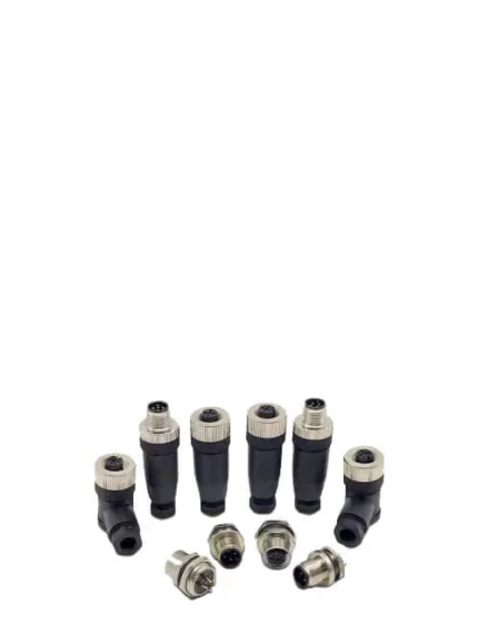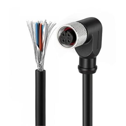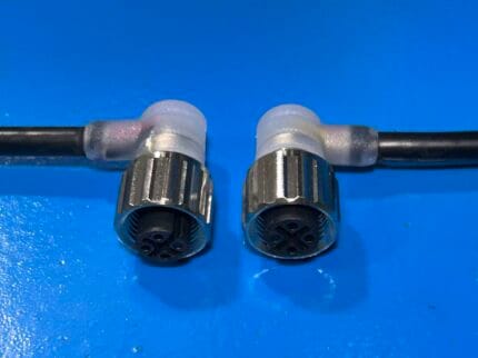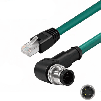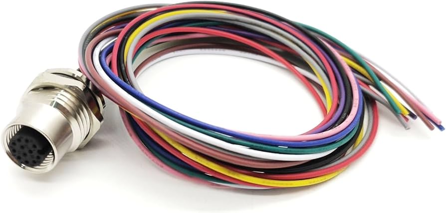
M12 12-Pin Bulkhead Cable with Flying Leads
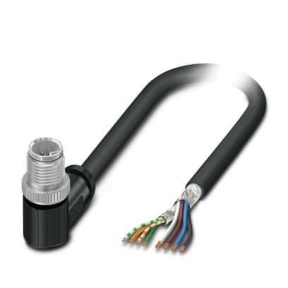
An M12 12 pin bulkhead feedthrough to open flying leads, front or rear mount, each lead marked to your pinout and cut to your panel thickness. Twelve signals through one cutout, with the panel seal carried at the flange.
Last updated: 13 September 2026
Overview
Drilling twelve holes in a cabinet is not a plan. An M12 12 pin bulkhead gets a dozen signals through one cutout, carries the panel seal at the same time, and hands the inside of the cabinet a bundle of leads that are already cut, stripped and marked. The bulkhead takes the outside abuse; the flying leads land on your terminal block. Built to your panel thickness and your pinout, it turns a wiring job into a reading job.
Key Specifications
| Connector | M12 12-position female, bulkhead mount |
|---|---|
| Coding | M12 A-coded, 12-position |
| Mounting | Front-panel or rear-panel thread, to order |
| Signal side | Flying leads, individually marked |
| Lead marking | Numbered sleeve, printed flag or heat-shrink legend, to order |
| Lead end | Tinned, ferrule or stripped, to order |
| Lead length | OEM build to your terminal layout |
| Jacket | PVC standard; PUR for oil-exposed cabinets |
| Sealing | Panel gasket; O-ring options per build |
Front mount or rear mount?
Decide this before the panel is cut, because it changes the cutout, the gasket position and the assembly sequence on your line. Front mount is the common answer for machine cabinets; rear mount is what you want when the panel can only be reached from one side, or when the connector has to be replaceable without opening the enclosure.
| Mounting | How it goes together | Best for | Note |
|---|---|---|---|
| Front mount | Nut goes on from outside the panel | Cabinets with clear access to the front face | The gasket sits between the flange and the panel |
| Rear mount | Body pushes through from inside | Blind panels and doors opened from one side | Needs a cutout tolerance the flange can cover |
| Threaded body with nut | M12 panel feedthroughs are commonly supplied with an M16 x 1.5 thread | General machine panels | Confirm the thread and cutout on the receptacle you specify |
| Flange with screw holes | Two or four screw fixings instead of a nut | Thin panels and composite enclosures | Screw pitch follows your panel drilling |
The 12-position shell is part of the same M12 connector family as the 4-pin and 8-pin bodies, so the coding, the thread and the mating face all follow the same series of standards.
M12 panel feedthroughs are commonly supplied with an M16 x 1.5 mounting thread, but there is no single figure that covers every maker. Give us the receptacle part number or the drawing and we machine and assemble to it. Our M12 bulkhead panel connector with pigtail covers the same decision in A, D and X coding.
Panel cutout and sealing
The seal is a system, not a part. There is the gasket or O-ring between the connector flange and the panel, the interface seal between the two connector halves, and the cable entry on the inside. An ingress rating applies to the assembled, mated pair — an unmated connector on a spare port is an open hole.
- Panel thickness — tell us the range you work to. The thread engagement has to cover the thinnest panel in the family.
- Gasket material — the gasket sits under the flange and is compressed by the nut, so over-torquing does not improve the seal.
- Surface finish — a painted or powder-coated panel seals better than a scratched one; a rough cutout edge will not.
- Torque — bulkhead nuts are tightened to the connector maker’s figure at final inspection, and the seal is checked on every unit where a rating is specified.
- Cutout — size and any anti-rotation flat, per the receptacle you specify.
M12 12-position conductor colors
The twelve-position A-coded arrangement and its conductor colors are the industry-standard convention for M12 A-coding under IEC 61076-2-101. It is a convention, not a law: we build to the pinout you send, and the color set below is the default only when nothing else is specified.
| Pin | Conductor color |
|---|---|
| 1 | Brown |
| 2 | Blue |
| 3 | White |
| 4 | Green |
| 5 | Pink |
| 6 | Yellow |
| 7 | Black |
| 8 | Gray |
| 9 | Red |
| 10 | Violet |
| 11 | Gray and pink |
| 12 | Red and blue |
Flying leads: marking and end finish
Twelve identical conductors arriving at a terminal block is where commissioning time goes. Marking is the cheapest thing you will ever add to a harness. Pick the combination that matches the cabinet:
| Marking | End finish | Best for |
|---|---|---|
| Numbered sleeve | Tinned or stripped | Fast commissioning, terminals in any order |
| Printed flag | Ferrule | Dense cabinets where sleeves will not fit |
| Heat-shrink legend | Tinned | Builds that see vibration or oil |
| Bare copper, bundled | Stripped | Soldered board terminations |
Typical applications for this M12 12 pin bulkhead
- Encoder and valve-block terminations in dense cabinets
- Panel transitions on packaging and assembly machinery
- Test fixtures needing a single-hole 12-signal pass-through
- OEM machine retrofits where the existing cutout has to be reused
- Cabinet service interfaces, alongside our control cabinet service interface with RJ45 and USB-C
- High-density signal runs that would otherwise use M12 12-pin cordsets
How to specify your build
- Coding and pin count — 12-position A-coded here; other counts on request.
- Mounting — front or rear, thread size, and panel thickness range.
- Panel cutout, including any anti-rotation feature.
- Mating face gender — what plugs into it from outside.
- Lead length, measured to each terminal rather than as one overall figure.
- Marking — numbered sleeve, printed flag, or heat-shrink legend.
- End finish — tinned, ferrule or stripped.
- Jacket and sealing, and what the panel face is exposed to.
Workmanship and testing
Workmanship follows IPC/WHMA-A-620 Class 3 and the line runs under ISO 9001. Conductors from 32 to 12 AWG are in range. Continuity and pinout are verified on 100% of units before packing; if you specify an ingress rating, seal checking on the batch can be quoted.
Custom builds and ordering
Prototype builds start from 5 pcs and ship in 3 working days; production orders start at MOQ 500 pcs and ship 14 working days after approval. New overmold tooling adds about 10 working days. OEM and ODM builds ship under your part number and labeling, with material certificates and first-article reports available on request.
Related panel and M12 assemblies
- M12 bulkhead panel connector with pigtail, A, D and X coding
- M12 12-pin cable for encoders and valve blocks
- M12 8-pin A-coded IP67 waterproof extension cable
- M12 A-coded PVC and PUR straight or right-angle extension cable
- M12 drag chain cable for continuous flexing
- IP67 RJ45 panel coupler, Cat6A shielded bulkhead feedthrough
Full range: circular M8 and M12 cable assemblies and panel mount cable assemblies.
Frequently Asked Questions
What thread and cutout does it need?
M12 panel feedthroughs are commonly supplied with an M16 x 1.5 mounting thread, but it varies by maker. Send the receptacle part number or the drawing and we machine to it rather than guessing.
Can the leads be different lengths?
Yes. Give us the terminal layout and each lead is cut to reach its own position, which keeps the bundle tidy instead of leaving a foot of slack coiled in the cabinet.
Will it seal against a painted panel?
Yes, provided the surface around the cutout is flat and the gasket is compressed evenly. A rough or scratched cutout edge is the usual cause of a panel that leaks.
Do you mark the leads?
Every lead can be marked with a numbered sleeve, a printed flag or a heat-shrink legend. It costs little and saves the most time at commissioning.
What is the minimum order?
Prototypes start from 5 pcs and ship in 3 working days. Production runs start at 500 pcs and ship 14 working days after approval.
| Connector | M12 12-position female, bulkhead mount |
|---|---|
| Mounting | Front-panel or rear-panel thread, to order |
| Signal side | Flying leads, individually marked |
| Lead length | OEM build to your terminal layout |
| Jacket | PVC standard; PUR for oil-exposed cabinets |
| Sealing | Panel gasket; O-ring options per build |
| Coding | M12 A-coded, 12-position |
| Lead marking | Numbered sleeve, printed flag or heat-shrink legend, to order |
| Lead end | Tinned, ferrule or stripped, to order |