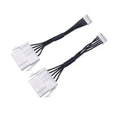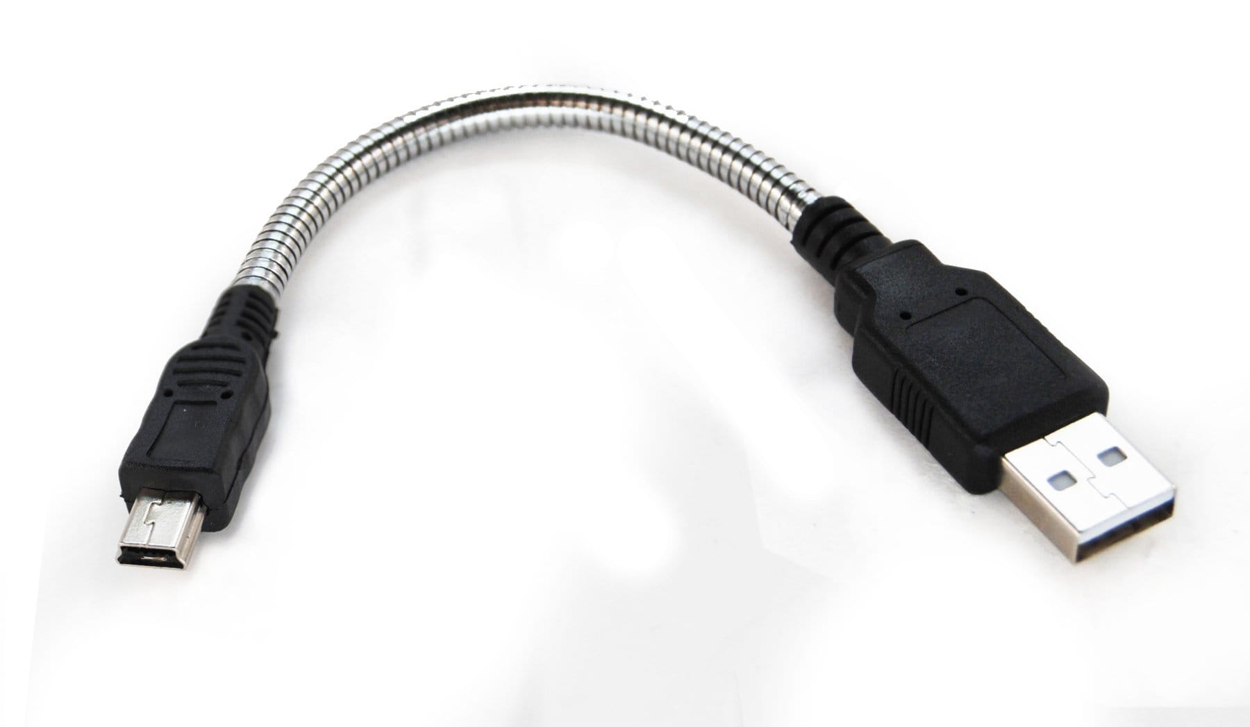
Shapeable USB Cable with Formable Stainless Core
A shapeable USB cable holds the bend you set, so a camera, scanner or POS lead stays routed without a clip or a tie. The stainless core carries no current: power and data conductors are sized in copper to your drawing.
A shapeable usb cable answers a complaint that never appears in a datasheet. The connector is right, the link works, and the lead simply refuses to stay put. A webcam droops between shifts. A counter scanner drags its own cord across the benchtop. Someone re-tapes a test fixture every morning. Slip a stainless shaping element into the cable and the lead keeps the curve you give it, so it holds position with no clip, no tie and no molded stiffener needed.
Most of what we run winds enamelled copper around that steel element. Current and data travel in the copper. The steel contributes nothing electrically – it is there purely to hold a position. Nearly everything below follows from that division of labor, and from one distinction worth reading before a drawing goes out.
Formable, not heat-activated: the distinction that saves a sample round
The name memory wire gets attached to two materials that behave nothing alike. Settling which one you mean costs nothing now and a fortnight later.
| What we build | What we do not build | |
|---|---|---|
| Response to a bend | Keeps the shape you put in | Recovers a trained shape on heating |
| Physical basis | The metal yields and stays yielded | A reversible phase change |
| Metal | Stainless shaping wire | Nickel-titanium |
| Typical job | Leads that must stay routed | Thermal triggers, latches, actuators |
| Price | A small fraction of the alloy | Many times the stainless figure |
| Joining the end | Crimp, weld, or held in the overmold | Crimp or weld; tin will not take |
The middle column is ours. A cord that hauls itself back to a remembered curve when warmth or current is applied is an actuator built from a shape memory alloy. We do not build those, they are sourced through a different supply chain, and they are not what this page is about. Say which you mean in the first message and nobody pays for samples to find out.
The steel inside does not carry current
This is the correction we make most often on incoming drawings. Stainless resists current something like forty times as much as copper does, so a shaping element stout enough to hold a curve is not a power path and not a substitute for copper area. On a USB cord that cuts two ways at once: the supply conductors have to be sized in copper for whatever the load draws, and the pairs carrying data have to be sized and laid up for the rate the link runs.
So the element does a single job, and the cord is otherwise specified as an ordinary USB cord. If a design wants the element tied to ground or used as a shield drain, we will build that, but we will also say what it does to the resistance of the path you just created – quietly accepting it would not help either of us.
Sizing copper for the power your device negotiates
There is no amperage stamped on this page on purpose. The figure depends on which profile the two ends settle on, how long the run is, how much drop the load tolerates and how hot it gets – so a number borrowed from some table ends up on drawings where it does not hold.
| Give us | What it settles |
|---|---|
| The charging profile the two ends negotiate | How much current the copper must carry |
| The length of the run | Voltage drop, which is usually what actually limits you |
| Drop you can live with at the load | Turns a preference into something we can test to |
| Ambient temperature, and whether it is bundled | How hard the same copper can be worked |
With those four we size the conductors, build, and continuity-test to the drawing. What we will not do is print a current figure because it reads well in a listing. Where an assembly has to be verified against a named standard, tell us which and we will price the test.
The connector itself and the way power is negotiated are covered in the general reference on USB-C.
What wears out first on a wound conductor
In this build the enamelled copper lies against steel, and steel is the harder of the two. Flex the cord and the coating gets rubbed. Rub it enough times and the coating gives way, copper meets steel, and a fault appears that only shows itself at one particular angle. On the bench that looks like a flaky peripheral: connects, drops out, comes back when the cord is nudged.
How soon that happens comes down to three things, all decided on paper. The tightness of the curve leads – a sharp hook stresses the winding far more than a lazy sweep does. Next comes whether some layer keeps the copper off the steel, which is the whole point of a served element. Last is the coating itself, and that one forces a genuine compromise.
| Coating | Stripped by a solder bath | Rubbing resistance | Right when |
|---|---|---|---|
| Polyurethane, solderable grade | Yes, at the bath temperature the wire maker states | Fair | Throughput and termination yield lead |
| Polyester or polyesterimide, solderable grade | Yes, bath runs hotter | Good | A higher thermal class without losing solder stripping |
| Polyesterimide, polyamideimide, polyimide | No – chemical, mechanical or laser | Excellent | Bend life leads and slower stripping is fine |
That compromise is the one place where a shaping element really changes how the part gets made. Solderable coatings come off and tin in a single controlled dip, which protects yield on thin conductors. Tougher coatings survive the rubbing but want a different stripping route, and we flag which your drawing implies before quoting rather than afterwards.
Fast data and a metal core: verify, do not assume
Drop a metal element into a cord and the space the high-speed pairs occupy changes. On a charging lead that barely matters. At superspeed rates it can, and we will not hand you a figure for it: geometry, pair lay and screening all interact, so the straightforward answer is that the build gets measured, not asserted.
So tell us the rate and the length up front. On a link that is already marginal we would rather say that a shaping element is a poor fit than take the order.
Routed leads that also have to stay locked together usually end up on one of these instead: the USB-C screw locking cable, the circular USB-C screw cable, or the sealed USB-C screw cable. Where the cord has to leave a housing sideways, the right angle USB-C cable is the tidier fix.
Joining the core at each end
Tin does not wet stainless the way it wets copper. Plain rosin flux gives a cold joint, and anything fierce enough to cut into the steel leaves residue behind a connector where we would rather it were not. So the element stays out of the circuit: crimped, spot welded, or anchored inside the overmold at the strain relief.
Anchoring is where the cheap copies of this part come apart. An element left free to slide slowly backs out of the strain relief and ends up either through the jacket or jammed into the connector shell. Assemblies that get repositioned a lot need more of it anchored, and that is worth a line on the drawing.
When a shapeable USB cable is the wrong tool
Two situations, and we would sooner decline the work than ship the wrong part.
Continuous movement, to begin with. A shaping element is set-and-leave; put it in a carrier and it work-hardens and snaps. Anything traveling on an axis belongs on a drag-chain harness or a teach pendant cable. Cords that get yanked rather than posed are better served by a tougher jacket, as on the aramid reinforced USB-C cable.
The other is a run that is dressed once during install and never touched again. A molded or pre-formed strain relief beats a shaping element there: it costs less, it repeats better, and there is nothing for the installer to set.
Where the job genuinely is an aimable head, look at the USB3 vision camera cable and the POS USB-C PD cable. The same shaping construction also turns up in the memory wire composite harness and the formable probe cable.
Seven lines to put on the drawing
| Write this | Because |
|---|---|
| Conductor count, and copper size per conductor | The element carries nothing |
| Coating grade, or the bend life you need | Sets the stripping route and the yield |
| The radius the lead will be posed to | Dominates how long the winding lasts |
| Whether the element is served or bare | A wrap keeps copper off the steel |
| How each end anchors it | Stops it backing out of the strain relief |
| Data rate and overall length | Decides whether the geometry needs measuring |
| Jacket compound and color | Feel in the hand, and survival in the environment |
How the build and the inspection work
Four lines and roughly forty assemblers at our Longgang plant in Shenzhen turn out close to a million pieces a year, to IPC-WHMA-A-620 Class 3 inside an ISO 9001 system. We work 32 to 12 AWG and check continuity and pinout on every piece before it is packed. Over a hundred tool sets are cut in-house, so an overmold does not sit waiting on a toolmaker. A jacketed sample leaves in three working days; series work opens at 500 pcs and ships fourteen working days after you sign the sample off.
The rest of the family sits under custom wire harnesses.
Frequently asked questions
Does the shaping element carry power or data?
No. Stainless resists current roughly forty times as much as copper, so the element only holds a position. Power and data travel in the copper conductors, sized to your drawing.
Can the element be soldered to a terminal?
Not with ordinary flux. It is normally crimped, spot welded, or anchored inside the overmold at the strain relief, and it stays out of the electrical path entirely.
Will it survive a drag chain or a moving axis?
No. A shaping element is pose-and-leave; cycling it work-hardens the steel until it cracks. For continuous motion you want a drag-chain harness or a teach pendant cable instead.
Can you strip any enamel we specify?
Solderable grades come off in a controlled bath. The harder high-temperature grades need chemical, mechanical or laser removal, and we will tell you which your drawing implies before we quote rather than after.
Do you publish a current rating for the cord?
No. It depends on the profile the two ends negotiate, the length, the drop you allow and the ambient temperature. Give us those four and we size the copper, then build and test to the drawing.
Do you stock these?
No. Every one is built to your drawing, which is also why there is no amperage printed on this page.
Each assembly is built and inspected against the drawing you send. Nothing here is a published rating.
| Construction | Enameled copper wound on a stainless shaping core |
|---|---|
| Core Material | Stainless steel shaping wire, formable / dead-set |
| Core Function | Holds position; carries no current |
| Conductor | Enameled copper, wound on the steel core |
| Conductor Count | Stated per your drawing |
| Conductor Size | Stated per your drawing |
| Enamel Grade | Stated per your drawing (solderable or scrape-resistant) |
| Shielding | Stated per your drawing |
| Jacket Material | Stated per your drawing |
| Overall Diameter | Stated per your drawing |
| Bend Cycles | Stated per your drawing |
| Termination | Stated per your drawing |
| Build and Inspection | IPC-WHMA-A-620 Class 3, 100% continuity and pinout, ISO 9001 |
Related products