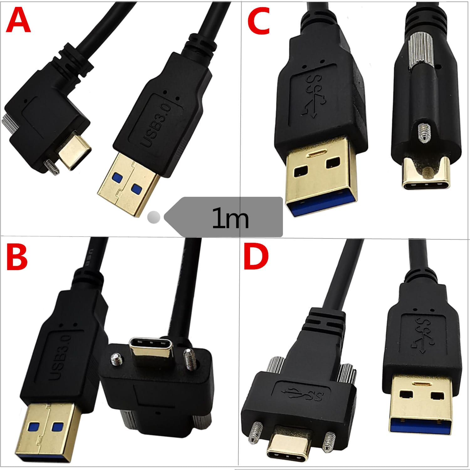
USB-C Screw Locking Cable, Side or Top 10Gbps 100W / 240W
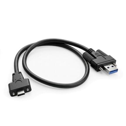
A USB-C screw locking cable offered with the retention screws on the side or on the top face of the plug, so the assembly matches the receptacle your panel was already tooled for. 10 Gb/s data, 100 W or 240 W power delivery, knurled M2 screws held captive in the overmold.
Overview
Once an enclosure faceplate is tooled, the position of the two threaded posts beside the receptacle is fixed, and the plug has to follow it. This USB-C screw locking cable is built both ways — screws on the broad faces of the plug, or on the narrow face — so a customer is never forced to redesign a panel after the mechanical layout has been frozen. Both variants run 10 Gb/s data and carry 100 W or 240 W.
Key Specifications
| Category | Screw-Lock Molded Cable |
|---|---|
| Interface | USB-C, USB 3.2 Gen 2 |
| Data rate | 10 Gb/s |
| Power delivery | PD 3.0 100 W or PD 3.1 EPR 240 W |
| Retention | Side screw or top screw, knurled M2, captive |
| Shielding | Aluminum foil plus mylar, approx. 85 percent braid |
| Jacket material | TPE |
| Jacket OD | approx. 4.8 mm |
| Lengths | 0.5 / 1 / 2 m |
| Application | Docks, drive enclosures, kiosks, industrial tablets |
| Conductor | Per your specification |
| Screw thread | M2, pitch and post depth confirmed to your receptacle |
Side screws or top screws: choosing the variant
Both variants use the same plug, the same cable and the same captive knurled M2 screws. The only question is which two faces of the receptacle carry the threaded posts, and that is decided by the hardware around the port rather than by preference.
| Variant | Where the screws sit | Choose it when | Watch out for |
|---|---|---|---|
| Side screw | On the two broad faces of the plug, one each side | The port has clear space left and right, and the cable should dress flat against a surface | Needs clearance on both sides for a finger or a driver |
| Top screw | On the narrow face, above and below the connector tongue | A kiosk bezel, a tight backplane or neighboring connectors leave no room at the sides | The cable stands off the panel, so allow depth in the enclosure |
| Either, screws omitted | No retention | The device has an unthreaded consumer port and the run is static | The plug then relies on friction alone |
What the screws actually engage
The screws pass through the overmold and pick up threaded posts that are part of the device receptacle, so the retention load goes into the panel and not into the plug tongue. The screws are captive in the overmold and removable, which means a damaged thread can be replaced in the field without discarding the cable. Screw post depth varies between receptacle manufacturers even when the pitch matches, so we confirm both against the drawing and recommend a sample evaluation on the actual hardware.
Data and power
- USB 3.2 Gen 2 signaling at 10 Gb/s over the standard four-lane USB-C wiring.
- Power delivery at 100 W under PD 3.0, or 240 W under PD 3.1 EPR, selected by build.
- Aluminum foil plus mylar wrap with roughly 85 percent braid coverage over the high-speed pairs.
- TPE jacket, chosen for a small bend radius inside tight enclosures.
- Standard lengths 0.5 m, 1 m and 2 m; other lengths on request.
The 240 W build is the one to specify when the cable also carries display and data to a dock or a drive enclosure that powers downstream devices. An EPR power contract depends on the source, the sink and the cable electronics all supporting the same profile, so we confirm it on your hardware before volume release rather than assuming it. Where the run is longer than a passive assembly can hold, see the USB-C active optical cable.
Identifying the variant on an existing cable
Look at the plug end on, with the USB-C tongue centered. If the two screws sit left and right of the tongue you have a side-screw build; if they sit above and below it, a top-screw build. If the plug has no screws at all but the receptacle has posts, you are holding a standard cable that was never going to stay put. A photograph of the plug face and of the receptacle is usually enough for us to identify the build. The connector itself is a standard USB-C plug, so it still mates and still charges on an unthreaded port — you simply lose the retention.
Typical applications for this USB-C screw locking cable
- Docking stations and multi-port expansion enclosures
- External drive enclosures where a disconnection during a write is unacceptable
- POS terminals, kiosks and self-service machines that are serviced but not supervised — see our POS USB-C PD cable
- Industrial tablets and panel PCs mounted on vehicles or machinery
- USB-C ports built into a panel front plate, alongside the flush mount USB-C receptacle
How to specify your build
- Variant: side screw or top screw, read off the receptacle or the device drawing.
- Screw thread and the depth of the threaded posts on the receptacle.
- Power profile: 100 W or 240 W, and whether the device actually supports EPR.
- Length, and whether the run bends tightly inside an enclosure.
- Other end: USB-C, USB-A, a right-angle plug, or a panel receptacle.
- Quantity, and whether this is a prototype or a production order.
Ordering and lead time
USB-C Screw Locking prototype builds start from 1 to 50 pcs and are out in 3 working days. Production is quoted from 500 pcs at 14 working days after sample approval. Tooling not already held adds around 10 working days. Your part number and labeling go on OEM and ODM USB-C shipments, and material certificates plus first-article reports are available.
Workmanship and testing
USB-C Screw Locking builds are assembled and inspected to IPC/WHMA-A-620 Class 3 criteria, with ISO 9001 as the quality system over 32 to 12 AWG work. Every USB-C unit is checked for 100% continuity and pinout before packing, and seal checking is quoted whenever an ingress rating is on the drawing.
RoHS and REACH declarations are provided per project together with the agreed test reports; the documentation scope is listed under certifications and compliance. If your drawing specifies a UL style, we build to that drawing and supply the UL reference with the shipment instead of substituting an equivalent. Injection parameters for this part are developed against the jacket material using the approach documented under overmolding and injection molding. More background: our build-to-print process. Any tooling we cut for this part stays yours, maintained in our own tool room under your part reference.
Related USB-C assemblies
- USB4 screw lock cable, 80 Gb/s dual screw
- Right-angle USB Type-C screw-lock cable
- IP67 waterproof USB-C screw cable
- USB-C Gen2 data cable, 10 Gbps with 100 W
- Circular USB-C screw cable with M12 style coupling
Full range: screw-lock molded cable.
Frequently Asked Questions
How do I know whether I need the side or the top variant?
Look at the receptacle. The screws have to line up with the threaded posts, and there is no adapter between them. Send a photo of the port if you are not sure.
Do the screws work on a normal consumer USB-C port?
No. An unthreaded port gives the screws nothing to engage, and the plug then behaves as a standard friction-fit USB-C cable.
Is 240 W available on every build?
It is available as a build option, but the power contract is only reached if the source, the sink and the cable electronics all support the EPR profile. We confirm that on your hardware first.
Can the screws be replaced if a thread is damaged?
Yes. They are removable knurled M2 screws, captive in the overmold so they stay with the assembly.
What is the minimum order?
Evaluation units run from 1 to 50 pcs, turned around in 3 working days. Volume starts at 500 pcs and ships 14 working days after approval.
| Category | Screw-Lock Molded Cable |
|---|---|
| Interface | USB-C, USB 3.2 Gen 2 |
| Data rate | 10 Gb/s |
| Power delivery | PD 3.0 100 W or PD 3.1 EPR 240 W |
| Retention | Side screw or top screw, knurled M2, captive |
| Shielding | Aluminum foil plus mylar, approx. 85 percent braid |
| Jacket material | TPE |
| Jacket OD | approx. 4.8 mm |
| Lengths | 0.5 / 1 / 2 m |
| Application | Docks, drive enclosures, kiosks, industrial tablets |
| Conductor | Per your specification |
| Screw thread | M2, pitch and post depth confirmed to your receptacle |