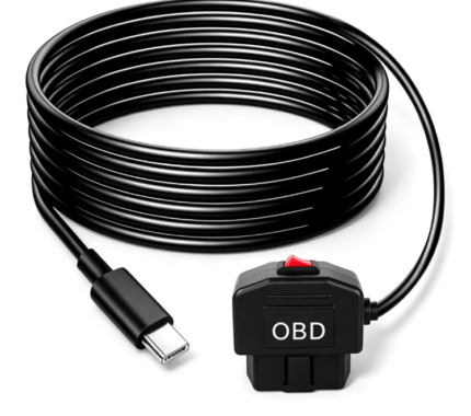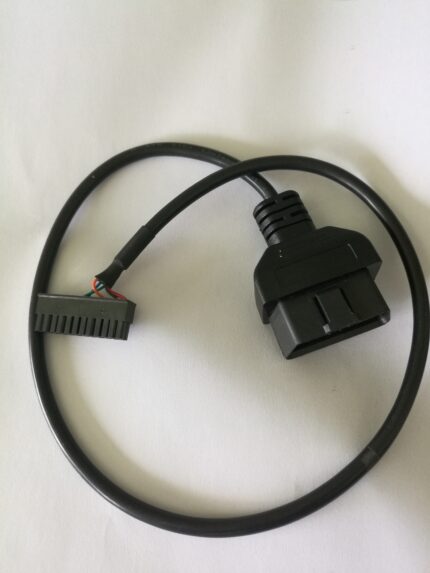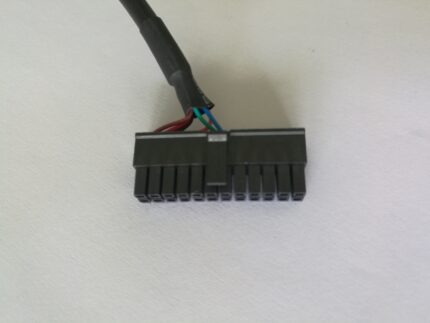
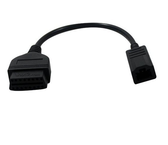
OBD-II 16-Pin Female to 3-Pin Diagnostic Lead Cable
An obd2 lead cable that taps power, ground and one signal off a J1962 16-pin port and brings them out to a 3-pin male plug. Short by design, so low-level sensor lines stay clean. Built to the pinout, gauge and length you send.
Overview
An obd2 lead cable of this type is a tap, not a scanner. One end carries a J1962 16-pin female socket, the other a 3-pin male plug, and there is nothing electronic in between: no chip, no level shifter, no protocol conversion. It exists to pull three conductors off a diagnostic port or a sensor loom so you can feed a tachometer, a data logger, a trigger input on test equipment, or a small accessory you would rather not splice into the factory harness. Which three of the sixteen cavities get wired is a decision you make on the order, and it is the only decision that really matters on this part.
Key Specifications
| Cable Type | Diagnostic Lead Cable |
|---|---|
| Connector A | OBD-II J1962 16-Pin Female |
| Connector B | 3-Pin Male |
| Application | Engine / Sensor Harness Tapping |
| Function | Passive tap, no active electronics in line |
| Pins wired | 3 of 16 cavities, selected on the order |
| Length | Stated per your drawing |
| Jacket material | Stated per your drawing |
| Testing | 100% continuity and pinout check before packing |
Three conductors is a small budget: spend it on purpose
Sixteen cavities sit behind the port and you get three of them. That constraint is the point of the part, and it is also why so many of these leads end up in a drawer unused: somebody ordered the right plug with the wrong three pins. Think about what the far end actually needs before you choose, and remember that a tap is not a power distribution point.
| What you are feeding | The three lines to bring out | Why that combination |
|---|---|---|
| A tachometer or trigger input | Signal, signal ground, chassis ground | Signal ground is the reference the instrument measures against; chassis ground alone drifts with body currents |
| A data logger or small accessory | Battery positive, chassis ground, ignition or a switched line | Switched feed stops the device flattening the battery between jobs |
| A CAN logger | CAN high, CAN low, signal ground | The pair has to stay twisted right up to the contact or the common-mode rejection is gone |
| A sensor under test | Sensor output, sensor reference, ground | Low-level outputs are exactly what a long lead ruins |
| A bench supply for a module | Battery positive, chassis ground, signal ground | Size the conductor for the current, not for the connector |
The J1962 pinout, and which cavities are safe to commit to
The OBD-II connector defined by SAE J1962 allocates its sixteen positions by protocol rather than by function, which is why several of them are left to the vehicle maker. Four positions are effectively fixed on every vehicle, and those are the ones worth committing to on a three-wire tap.
| Pin | Assignment | What it gives you on a tap |
|---|---|---|
| 16 | Battery positive, unswitched | The feed most people are buying the tap for |
| 4 | Chassis ground | The current return; always safe |
| 5 | Signal ground | The clean reference; keep it separate from chassis ground |
| 6 | CAN high (ISO 15765-4) | Bus logging on modern vehicles |
| 14 | CAN low (ISO 15765-4) | The other half of the pair |
| 7 | K line (ISO 9141-2 / ISO 14230-4) | Legacy serial diagnostics |
| 2 | J1850 bus positive | Older North American protocol |
| 10 | J1850 bus negative | Older North American protocol, J1850 PWM only |
| 1, 3, 8, 9, 11, 12, 13 | OEM discretion | Varies by maker and by model year; verify before wiring to any of them |
Why this lead is short by design
Length is the enemy of a tap. A long conductor hanging off a low-level sensor output behaves like an antenna, and the capacitance of the run rolls off exactly the fast edges you are trying to capture on a scope or feed to a counter input. There is a second effect that bites people on the power pin: the port is fed from a fused circuit in the vehicle, and every meter of conductor between that fuse and your accessory takes voltage out of the budget. Keep the lead as short as the job allows, and if you genuinely need distance, order the run with a twisted, shielded pair and a heavier conductor on the power line rather than just asking for more length.
Construction
- J1962 16-pin female socket to a 3-pin male plug, straight through, no electronics.
- Stranded copper conductors; the cross section is stated on your drawing.
- Jacket material per your drawing, with oil-resistant compounds available for engine bay routing.
- Overmolded strain relief at both bodies, which is where a lead like this normally fails first.
- Unused cavities left unpopulated unless you ask for them to be wired.
What to send with the order
- The three pins you want brought out, read off the port or off your service documentation.
- Conductor cross section, decided by the current you will draw and by the run length.
- Length, and whether the lead has to cross a hot or moving part of the bay.
- Jacket – PVC for cab routing, something tougher for under-hood.
- Quantity, and whether this is an evaluation piece or a production run.
Typical applications for this obd2 lead cable
- Feeding a tachometer, a shift light or a trigger input on a data acquisition box during road testing
- Bench work where a module needs power without cutting into the vehicle harness, often alongside an OBD2 extension flat cable
- Powering a small accessory during diagnosis, paired with an OBD2 splitter and USB charger lead
- ECU and sensor loom work on the bench with a J1962 female to ECU board harness
- Fleet workshops that would rather replace a tap than repair a factory loom, next to the SAE J1939 OBD2 diagnostic cable
Workmanship and testing
OBD-II 16-Pin Female builds are assembled and inspected to IPC/WHMA-A-620 Class 3 criteria, with ISO 9001 as the quality system over 32 to 12 AWG work. Every OBD-II unit is checked for continuity and pinout before packing, and seal checking is quoted whenever an ingress rating is on the drawing.
Material declarations against RoHS and REACH are issued per project, alongside the dimensional and electrical reports agreed at quotation; see certifications, compliance and material declarations. Where your drawing names a UL style or another approval, the build follows your drawing and ships with the supporting document rather than a claim of our own. Overmold tooling for this part is designed and cut in our own tool room under overmold tooling cut in our own tool room, so the tool belongs to your program and a revision is a machining job rather than a new negotiation. More background: cable assemblies for automotive and EV.
Custom builds and ordering
OBD-II 16-Pin Female prototype builds start from 1 to 50 pcs and are out in 3 working days; production is quoted from 500 pcs at 14 working days after sample approval. Tooling not already held adds around 10 working days. Your part number and labeling go on OEM and ODM OBD-II shipments, and material certificates and first-article reports come with them on request.
Related diagnostic leads
- OBD2 Extension Flat Cable, 16-Pin Male to Female
- OBD2 Splitter USB Charger Cable, 16-Pin Pass-Through
- 16-Pin J1962F OBD2 Female Connector to ECU Board, Tyco 8-Pin Harness
- SAE J1939 OBD2 Diagnostic Cable, Type 2 Green 9-Pin
- OBD Power Cable for Dash Camera, OBD to USB Type-C
- 2+6 eBike Battery Connector Cable, IP67 Overmolded
- 7-Way RV Trailer Wiring Harness, Overmolded Blade Plug
Full range: automotive cable and wire harness.
Frequently Asked Questions
How many of the sixteen pins are actually wired?
Three, unless you ask for more. That is what keeps the lead cheap and the signal clean. Tell us which three when you order.
Can I run an accessory off the power pin?
Yes, but read the fuse label on the vehicle first. The port is fed from a fused circuit whose rating you should confirm, and size the conductor for that current over the length you are ordering.
Does it convert between protocols?
No. It is a passive tap. It carries whatever the vehicle puts on those pins, and your instrument still has to understand it.
Can I have all sixteen pins brought out instead?
Yes. That is a different build – a breakout to a 2×7 DIP header – and it is the right choice when you do not yet know which lines matter.
| Cable Type | Diagnostic Lead Cable |
|---|---|
| Connector A | OBD-II J1962 16-Pin Female |
| Connector B | 3-Pin Male |
| Application | Engine / Sensor Harness Tapping |
| Function | Passive tap, no active electronics in line |
| Pins wired | 3 of 16 cavities, selected on the order |
| Length | Stated per your drawing |
| Jacket material | Stated per your drawing |
| Testing | 100% continuity and pinout check before packing |
Related products
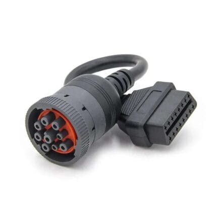
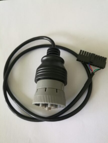
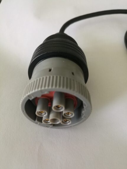
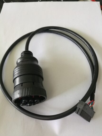
Heavy-Duty 9-Pin Industrial Diagnostic Cable Assembly
A heavy duty 9 pin cable with a 9-pin round industrial plug and a 14-pin 2x7 DIP bare end, for engine management diagnostics on trucks, marine diesel and heavy equipment benches. Verify the pinout against your service manual, since 9-pin assignments follow the engine maker rather than one specification.