2+6 eBike Battery Connector Cable, IP67 Overmolded
A 2+6 eBike battery connector cable is a sealed hybrid harness that carries two high-current power contacts and six low-current signal contacts inside one keyed housing, so a battery pack needs a single opening for both the main power path and its BMS communication.
Overview
A 2+6 eBike battery connector cable is a sealed hybrid harness that carries two high-current power contacts and six low-current signal contacts inside one keyed housing, so a battery pack needs a single opening for both the main power path and its BMS communication.
The obvious alternative is two connectors: a heavy power plug for the main current and a separate plug for the sense and communication lines. Two connectors mean two openings in the battery bay, two sealing interfaces to keep clean, two harness branches to route, and two chances to mate a plug onto the wrong half. Folding both into one housing removes all four problems, at the cost of a connector that has to be designed properly the first time.
That is why the format only works when the layout is treated as one system. The power contacts run hot and radiate magnetic noise; the signal contacts carry voltages the BMS has to read cleanly at millivolt level. Contact spacing, separation and return routing decide whether the six signal positions are genuinely usable or merely present. HKWIRE builds the assembly to your drawing or sample, so the pinout, the separation and any screening follow the design rather than a fixed catalog arrangement.
Assemblies are built to drawing or to sample, tested against limits agreed in writing before production release, and shipped as a finished cable rather than a loose connector.
Key Specifications
| Property | Value |
|---|---|
| Build Type | Build to drawing or build to sample |
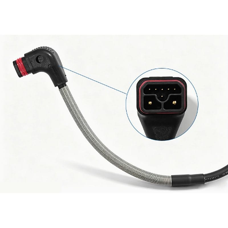
| Contact Layout | 2 power + 6 signal, 8 positions in one keyed housing |
| Power Contacts | 2 large gold-plated contacts for the main DC path |
| Signal Contacts | 6 small contacts for BMS, sense and control lines |
| Body Orientation | 90° right-angle, overmolded |
| Sealing | IP67 mated; IP68 on request |
| Face Seal | Molded silicone gasket at the mating interface |
| Cable Protection | Braided metallic sleeve, overmolded at both transitions |
| Power Conductors | High-strand copper, typically 12 to 8 AWG, sized to the duty |
| Signal Conductors | 26 to 22 AWG |
| Jacket Options | Silicone, TPE or PUR per the drawing |
| Marking | Printed or laser marking per node list |
| Testing | 100% continuity and pinout, dielectric withstand, crimp pull; seal test on request |
Where a Hybrid eBike Battery Connector Fits
An eBike battery connector that carries both the main current and the control signals is the usual answer once the pack has its own battery management system. The pack is no longer a dumb block of cells with two terminals; it is a device that reports temperature, state of charge and fault state, and it will not discharge unless the controller tells it to. All of that needs conductors, and those conductors have to reach the same place the power does.
The six signal positions typically divide into three functional groups. A pair carries BMS communication — most often CAN, sometimes a UART link — between the pack and the controller or charger. One or two lines carry NTC temperature sense from inside the pack. The remaining positions carry the wake, enable or interlock lines that decide whether the pack is allowed to discharge or charge. Which position does which job is a design decision recorded on the drawing, not something fixed by the connector.
It is worth being precise about what this interface is not. The 2+6 arrangement is a widely used layout across light electric vehicles, not a numbered international standard with one guaranteed pinout. Related variants exist with different signal counts, keying and current contacts, and two makers can use the same layout with different assignments. That is the practical reason a drawing or a physical sample is the only reliable way to specify one, and the reason we do not publish a single generic pinout here.
The 90° Overmolded Body
The cable leaves the connector at a right angle to the mating axis. On a battery pack, the space directly behind the interface is usually the space you do not have: the connector faces out of the pack while the route runs back along the frame, inside the downtube or under the deck. A straight exit forces the cable to turn immediately behind the connector, and that turn is where a jacket fails first.
Overmolding fuses the body and the cable into one piece. There is no separate backshell, no compression nut and no rear boot to be left loose or cross-threaded, and the strain relief is built into the transition rather than added to it. Our overmolding page covers how the tool and the material are chosen for that joint.
The trade-off is honest and worth stating. An overmolded assembly cannot be re-terminated in the field: if the cable is damaged, the whole assembly is replaced. For a battery-pack connector that is usually the right trade, because a field-repairable backshell is also a field-repairable leak path.
The Braided Sleeve: What It Protects Against
The braided metallic sleeve over the cable is there for mechanical reasons, not electrical ones. Its job is to stop the jacket being cut through by a sharp frame edge, chafed by a bracket it vibrates against, or chewed by rodents in a shed or a barn — the last being a real and frequently underestimated failure mode on equipment that lives outdoors.
It also spreads bending load. Instead of the bend concentrating at the point where the cable leaves the overmold, the braid holds the cable to a defined curve over its whole free length, which keeps the conductor and the jacket below their fatigue limits at the same stress cycle count. The flex and pull tests we run on finished assemblies are described on our testing and validation page.
Two things the sleeve is not. It is not the strain relief — that comes from the overmolded transition at the connector, and a braid whose ends are terminated badly is simply a stiff section. And it is not screening on its own. A braid only behaves as an EMI shield when it is bonded to the connector shell and its drain is terminated properly at both ends; if the drawing asks for screening, say so, because a decorative braid and a working shield look identical in a photograph.
Sealing at the Mating Interface
A molded silicone gasket sits in a groove around the face of the housing and is compressed when the two halves mate. Because the seal is a separate elastomer rather than a lip formed in the plastic molding, it keeps its resilience at low temperature, which matters on equipment parked outside through a winter.
On the cable side there is no second sealing interface: the overmold is the cable entry. A single-piece body leaves the mating face as the only path for water, and the gasket closes it. The assembly is rated IP67 with the halves mated, and IP68 is available on request.
Ingress ratings carry conditions. The figure applies to a connector that is fully mated, with a clean and undamaged gasket. An interface that is part-mated, or a gasket that has picked up grit or been nicked, is not sealed whatever the label says — which is why it is worth specifying the locked position and a service interval along with the connector itself.
Applications
The layout suits any pack that has to deliver current and report its own state through one serviceable connection:
- e-bike and e-motorcycle battery packs — main charge and discharge current together with BMS communication, temperature sense and enable lines
- Controller to battery bay — one interface carrying both supply and data, which removes a second branch and a second opening from the frame
- V2L discharge and fast-charge adapters — power and the protocol handshake on the same connector; see our V2L discharge adapter cable
- AGV and AMR battery modules — swappable packs docked and undocked many times a day, where one connector is easier to align than two
- Portable energy storage — expansion battery links that carry power and state-of-charge data between packs
- Outdoor power equipment — robotic mowers, ground station supplies and other outdoor machines that need sealing and abrasion protection together
Main power in this format commonly sits in the 20 A to 40 A continuous class, with short peaks set by the controller. Treat that as a starting point rather than a rating: the real continuous figure is fixed by the conductor size, the contact, the ambient and the duty cycle together, and the wire is selected against the actual duty rather than against a headline number.
Custom Builds, Testing and Ordering
A drawing for this assembly needs the connector series and its keying, the pinout with the function of each of the eight positions, the power and signal conductor sizes and stranding, the jacket material, the sleeve type and length, the overall length with tolerance, and the marking. Where the cable does not run straight, send the routing and the minimum bend radius as well as a length, because a length that works in a straight line can still be wrong once it is bent into a downtube.
Every assembly gets a 100% continuity and pinout check and a dielectric withstand test. Crimp pull testing is run to the applicable section, and seal testing is available for mated assemblies. Limits, sampling and records are agreed in writing before production release, so the acceptance criteria are the ones on your drawing rather than a default.
HKWIRE is ISO 9001 certified. Workmanship follows the IPC/WHMA-A-620 Class 3 acceptance criteria when the drawing specifies them; we do not claim to hold an independent IPC certification. RoHS and REACH declarations are issued per project. See also our eBike battery harness for packs without a signal interface and our BMS communication harness for rack-scale battery systems.
Material declarations against RoHS and REACH are issued per project, alongside the dimensional and electrical reports agreed at quotation; see certifications, compliance and material declarations. Where your drawing names a UL style or another approval, the build follows your drawing and ships with the supporting document rather than a claim of our own. The ingress rating is built into the joint, following the sealing structures set out in waterproof sealing design and validation and validated against IEC 60529 before release. More background: cable assemblies for automotive and EV. Tooling for this build is cut in our own tool room and belongs to your program, so a repeat run years later starts from the same tool.
Related Cable Ranges
| Build Type | Build to drawing or build to sample |
|---|---|
| Contact Layout | 2 power + 6 signal, 8 positions in one keyed housing |
| Power Contacts | 2 large gold-plated contacts for the main DC path |
| Signal Contacts | 6 small contacts for BMS, sense and control lines |
| Body Orientation | 90° right-angle, overmolded |
| Sealing | IP67 mated; IP68 on request |
| Face Seal | Molded silicone gasket at the mating interface |
| Cable Protection | Braided metallic sleeve, overmolded at both transitions |
| Power Conductors | High-strand copper, typically 12 to 8 AWG, sized to the duty |
| Signal Conductors | 26 to 22 AWG |
| Jacket Options | Silicone, TPE or PUR per the drawing |
| Marking | Printed or laser marking per node list |
| Testing | 100% continuity and pinout, dielectric withstand, crimp pull; seal test on request |