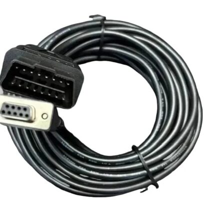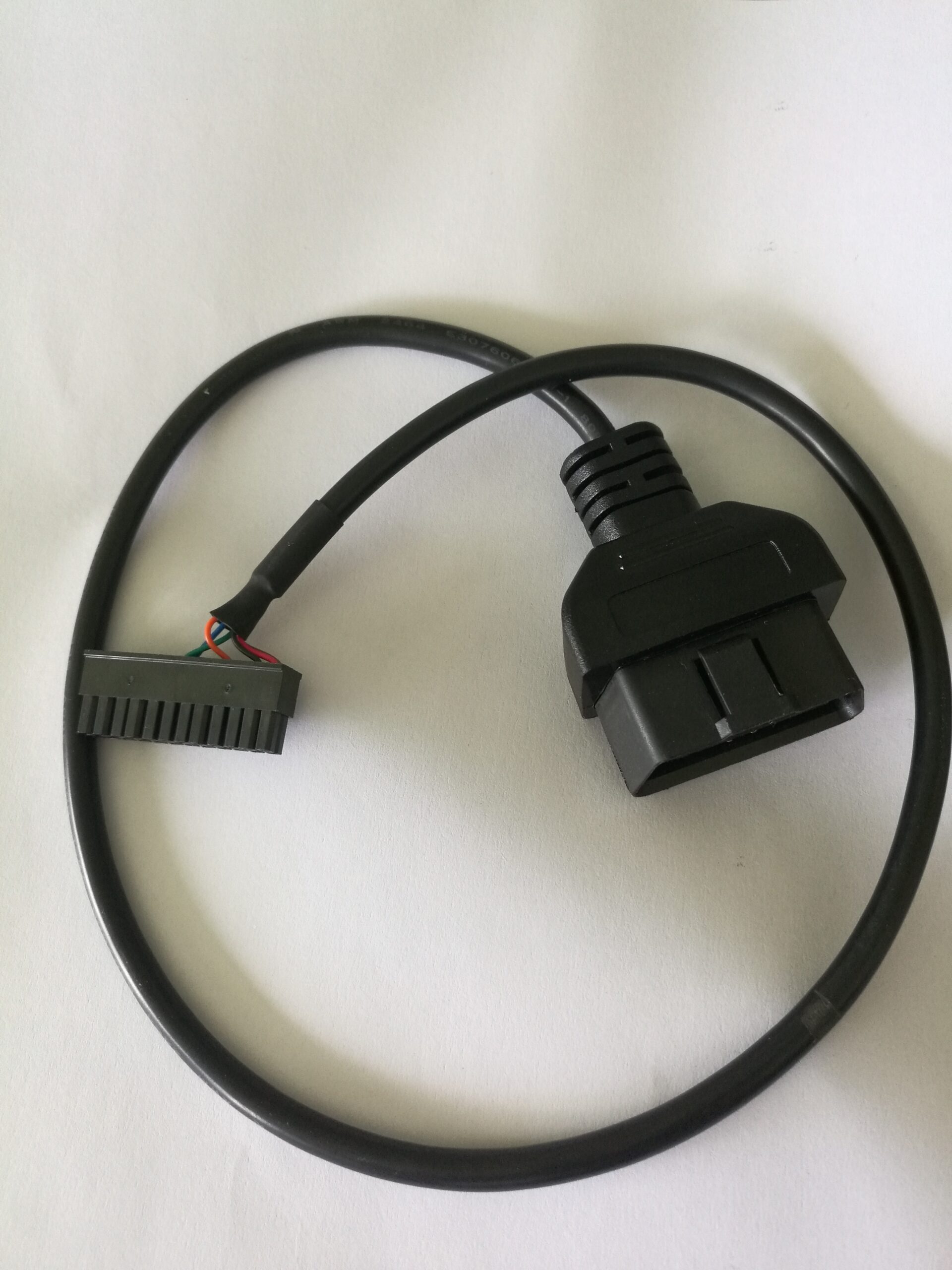
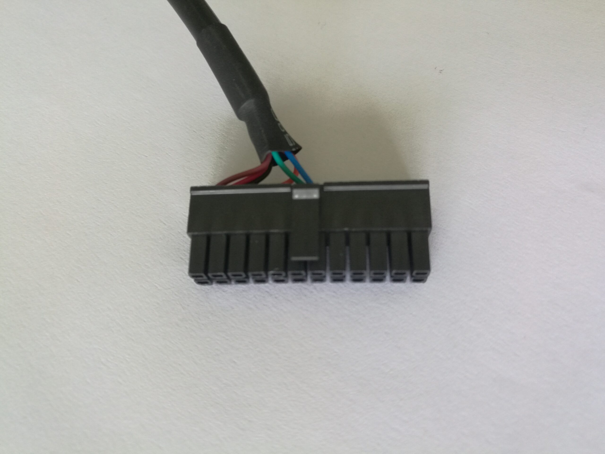
OBD-II 16-Pin Female to 14-Pin DIP Diagnostic Breakout Cable
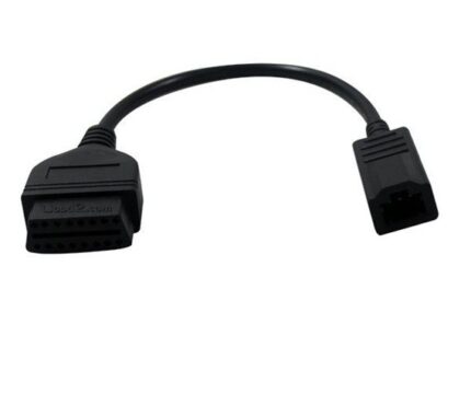
An obd2 16 pin dip cable breakout that brings fourteen of the sixteen J1962 signals out to a 2×7 DIP male header, so each line can be scoped, clipped or pushed into a breadboard on the bench. Straight through, no protocol conversion.
Overview
An obd2 16 pin dip cable is the tool you reach for when you do not yet know which line matters. The J1962 16-pin female socket goes on the vehicle side; the other end is a 14-position 2×7 DIP male header where each signal can be scoped, clipped with a grabber, or pushed straight into a breadboard. Fourteen positions for sixteen signals means two cavities are left behind, and deciding which two is the first real engineering decision on this part. It is a breakout, not a power lead: the header is a signal-level termination and should not be asked to carry starter-scale current.
Key Specifications
| Cable Type | Diagnostic Breakout Cable |
|---|---|
| Connector A | OBD-II J1962 16-Pin Female |
| Connector B | 14-Pin 2×7 DIP Male Header |
| Application | ECU Test Bench / CAN Tapping |
| DIP pitch | 2.54 mm between pins, 7.62 mm between rows |
| Mapping | 14 of 16 J1962 signals brought out; mapping per your drawing |
| Function | Breakout lead, no protocol conversion |
| Length | Stated per your drawing |
| Testing | 100% continuity and pinout check before packing |
Sixteen signals, fourteen positions: which two do you drop?
This is the question that makes the part interesting. If you drop the wrong two, the breakout is useless for the job you bought it for. The sensible default is to drop two of the OEM-discretion cavities, because those are the ones that vary by maker anyway, and keep every position that a published protocol uses. The table below is our default build; send your own map if you need something else.
| Header position | J1962 pin | What it carries | Why it is kept or dropped |
|---|---|---|---|
| 1 | 2 | J1850 bus positive | Kept – a published protocol line |
| 2 | 3 | OEM discretion | Kept – sometimes Ethernet or a maker bus |
| 3 | 4 | Chassis ground | Kept – always useful on a bench |
| 4 | 5 | Signal ground | Kept – the reference every measurement needs |
| 5 | 6 | CAN high | Kept |
| 6 | 7 | K line | Kept – ISO 9141 and ISO 14230 work |
| 7 | 8 | OEM discretion | Kept – often a second K line |
| 8 | 10 | J1850 bus negative | Kept – a published protocol line |
| 9 | 11 | OEM discretion | Kept |
| 10 | 12 | OEM discretion | Kept |
| 11 | 13 | OEM discretion | Kept |
| 12 | 14 | CAN low | Kept |
| 13 | 15 | L line | Kept – initialization on older protocols |
| 14 | 16 | Battery positive | Kept – the reason a bench module can run at all |
| Not brought out | 1 and 9 | OEM discretion | Dropped by default – the two that vary most by maker |
What the header can take, and what it cannot
A 2×7 DIP header is a prototyping convenience, not a power connector. Its posts are small, there is no locking and no strain relief, and it is designed to be plugged into a socket or a breadboard rather than to carry current. Two rules follow from that: keep the currents at signal level, and support the cable so its weight does not hang off the header.
- Fine: scope probes, logic analyzer leads, grabber clips, breadboard jumpers, a bench module drawing well under an amp.
- Not fine: anything that looks like a starter, a winch, an inverter or a compressor load. Use a dedicated power lead for those.
- Avoid: leaving the header lying on a bench where a stray strand or a tool can short pin 16 to a neighbor. Cap it or sleeve it when it is not in use.
Reading the J1962 side
The OBD-II connector in SAE J1962 allocates positions by protocol, so several of them are left to the vehicle maker. That matters on a breakout because it means some header positions will be live on one car and dead on another. Confirm with a meter before you wire anything permanent to pins 1, 3, 8, 9, 11, 12 or 13.
| J1962 pin | Assignment | What you would typically do with it |
|---|---|---|
| 4 and 5 | Chassis and signal ground | Reference for a scope or a bench supply |
| 6 and 14 | CAN high and CAN low | Bus capture with an interface or an analyzer |
| 7 | K line, ISO 9141-2 and ISO 14230-4 | Legacy serial sessions |
| 2 and 10 | J1850 bus positive and negative | Older North American protocol work |
| 15 | L line | Initialization on some older protocols |
| 16 | Battery positive | Feed a bench module through a fused lead |
| 1, 3, 8, 9, 11, 12, 13 | OEM discretion | Meter them first; treat as unknown until measured |
Construction
- J1962 16-pin female socket to a 2×7 DIP male header, straight through, no electronics.
- Stranded copper conductors; cross section stated on your drawing.
- The CAN pair kept twisted up to the header so the bus stays balanced on the bench.
- Overmolded strain relief at the socket, and a short body so the header carries no leverage.
- Optional shrouded header, or labeled positions, if the breakout will live on a bench.
How to specify your build
- The two pins to drop, or the full map you want instead of the default.
- Header style – plain posts, shrouded, or with a keyed shroud.
- Whether you want the CAN pair kept twisted to the header.
- Length, and whether a right-angle socket would suit the bench.
- Labeling – printed position numbers save a lot of bench time.
Typical applications for this obd2 16 pin dip cable
- Reverse engineering where you need a scope on every line before you know which matters
- ECU test benches and bench flashing rigs, alongside a J1962 female to ECU board harness
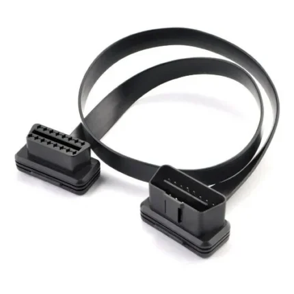
- Bus capture and analyzer work, paired with an OBD2 extension flat cable to keep the port clear
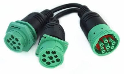
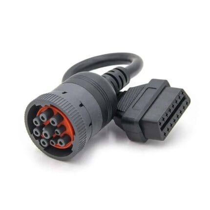
- Training and demonstration rigs where every signal needs to be visible, next to a Type 2 green 9-pin J1939 cable
- Machine harness work where the far end is a DT connector pigtail
Workmanship and testing
OBD-II 16-Pin Female builds are made to IPC/WHMA-A-620 Class 3 workmanship inside an ISO 9001 system, over a 32 to 12 AWG range. No OBD-II assembly is boxed before continuity and pinout are confirmed, and seal checking is quoted whenever an ingress rating is on the drawing.
Material declarations against RoHS and REACH are issued per project, alongside the dimensional and electrical reports agreed at quotation; see certifications, compliance and material declarations. Where your drawing names a UL style or another approval, the build follows your drawing and ships with the supporting document rather than a claim of our own. Where this build needs an overmold, the tool is designed, cut and maintained in our own shop under in-house mold making and overmold tooling, and it is never used for another customer’s program. More background: what changes on vehicle harness builds.
Custom builds and ordering
For OBD-II 16-Pin Female builds, prototypes run from 1 to 50 pcs with a 3 working day turnaround; volume orders begin at 500 pcs and ship 14 working days after approval. Tooling not already held adds around 10 working days. OBD-II builds go out under your part number and labeling, and material certificates and first-article reports are on offer.
Related breakout and bench leads
- 16-Pin J1962F OBD2 Female Connector to ECU Board Harness
- OBD2 Extension Flat Cable, 16-Pin Male to Female
- SAE J1939 OBD2 Diagnostic Cable, Type 2 Green 9-Pin
- 16-Pin OBDII Y Splitter Extension Cable, Heavy-Duty Extender
- DT Connector Pigtail Harness, 2 / 3 / 4-Pin Sealed
Full range: automotive cable and wire harness.
Frequently Asked Questions
Which two pins are left out, and can I change that?
The default build drops pins 1 and 9, both of which are OEM discretion positions. Yes, send your own map and we build to it.
Can I power a module from the header?
Only at signal-level current. The header has no locking and no strain relief; use a dedicated power lead for anything that draws real current.
Is the breakout shielded?
Shielding is stated on your drawing. Where the CAN pair is being captured we recommend keeping the twist to the header and terminating the drain properly.
Will every position be live on my vehicle?
No. Several J1962 positions are OEM discretion, so meter them before you wire anything permanent to them.
| Cable Type | Diagnostic Breakout Cable |
|---|---|
| Connector A | OBD-II J1962 16-Pin Female |
| Connector B | 14-Pin 2×7 DIP Male Header |
| Application | ECU Test Bench / CAN Tapping |
| DIP pitch | 2.54 mm between pins, 7.62 mm between rows |
| Mapping | 14 of 16 J1962 signals brought out; mapping per your drawing |
| Function | Breakout lead, no protocol conversion |
| Length | Stated per your drawing |
| Testing | 100% continuity and pinout check before packing |