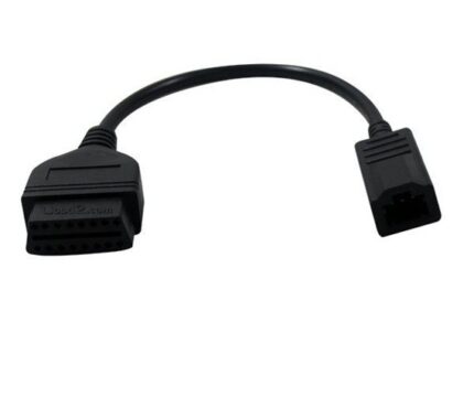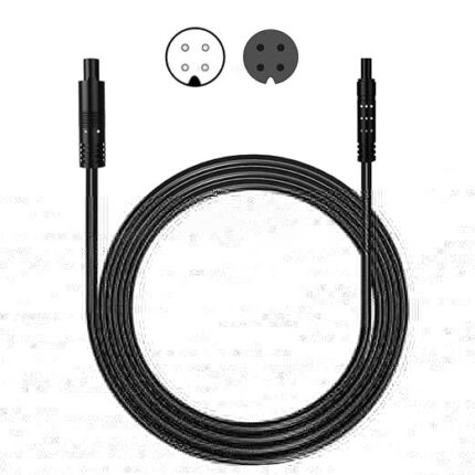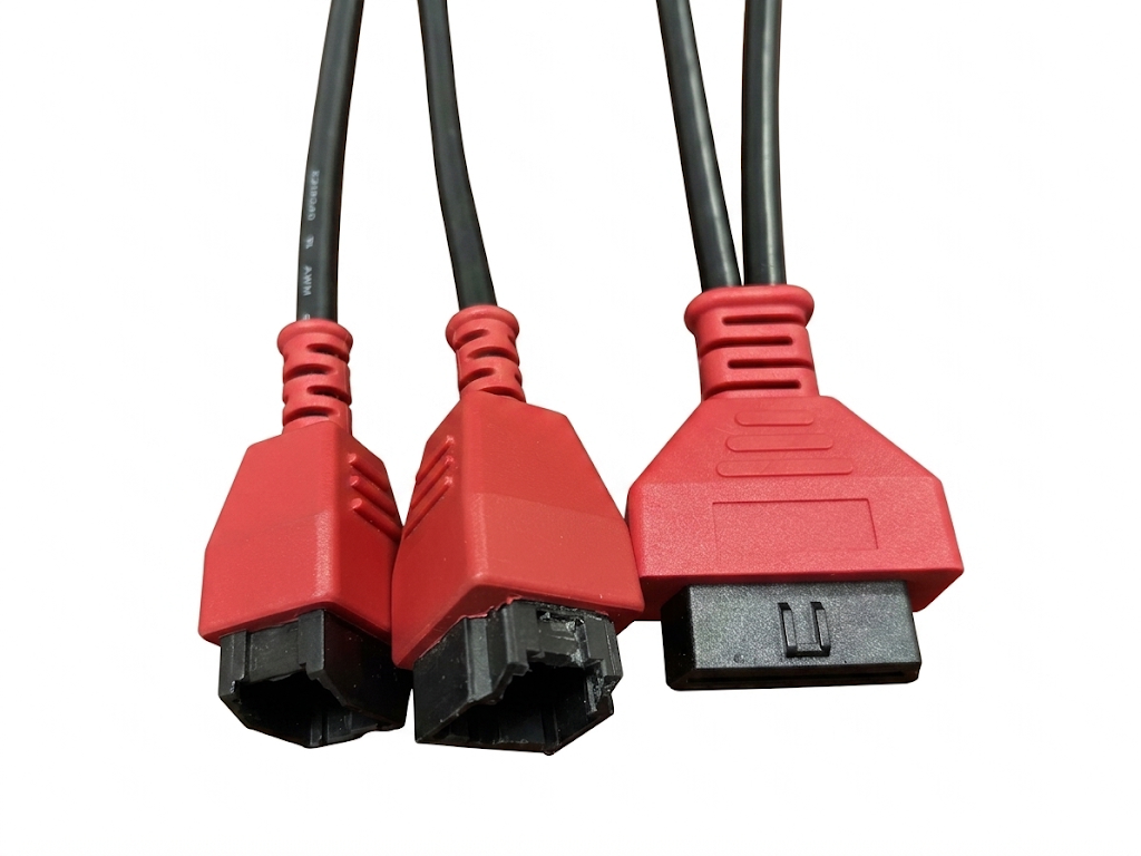
16 Pin OBDII Y Splitter Extension Cable, Heavy Duty OBD2 Male to Female Car Diagnostic Extender Adapter Cord
A 16 pin OBDII Y splitter extension lets a permanent device and a scan tool share one diagnostic port, and takes the mating cycles off the socket in the dash. Full 16-wire passthrough or a power-only tap.
Overview
Every vehicle has one diagnostic port and most fleets want two things plugged into it: a device that stays permanently, and a scan tool that visits once a quarter. A 16 pin OBDII Y splitter extension is the cheap way to have both without cycling the plug, and without wearing out the socket in the dashboard — which is the part that is expensive to replace. One leg feeds the permanent device, the other stays free for the tool.
Key Specifications
| Connector A | OBDII 16-pin J1962 male, molded plug |
|---|---|
| Connector B | Two OBDII 16-pin J1962 female sockets on the Y body |
| Pins wired | Full 16-wire pass-through, or a subset tap to order |
| Conductor | 32 to 12 AWG, per build |
| Cable | Flat ribbon standard; round jacket on request |
| Jacket | PVC standard; PUR where the lead runs through a door jamb or footwell |
| Length | 0.3 m standard; OEM build to order |
| Mounting | Loose lead, or a bracket and screw bosses on the Y body |
Why a splitter beats unplugging things
The vehicle-side connector is rated for a finite number of mating cycles, and in a working shop or a fleet service bay it gets cycled far more often than the vehicle designer imagined. A bent or spread contact in the dashboard socket turns into intermittent CAN errors that look like a module fault and cost an afternoon to find. A Y lead takes the wear: the tool plugs into the splitter, not into the car. The second reason is access. Many ports sit where a permanent device body will not fit, and a 0.3 m lead moves the working point out from under the dash. Background on the port itself sits in the OBD-II reference.
OBDII pin groups and what a splitter does with them
SAE J1962 assigns the pins by protocol, and which of them a splitter needs depends entirely on what is hanging off the second leg. A pure power tap needs two pins; a full pass-through needs all sixteen. The assignment below is the industry-standard one for a 12 V passenger vehicle port, quoted as a reference — your build is wired and tested to the pinout on your order.
| Pin(s) | Signal per SAE J1962 | What a Y build does with it |
|---|---|---|
| 4 | Chassis ground | Pass through to both sockets |
| 5 | Signal ground | Pass through to both sockets |
| 6 | CAN High (ISO 15765-4 and SAE J2284) | Pass through; keep the pair together |
| 14 | CAN Low (ISO 15765-4 and SAE J2284) | Pass through; keep the pair together |
| 7 | K line (ISO 9141-2 and ISO 14230-4) | Pass through for older protocol vehicles |
| 15 | L line (ISO 9141-2) | Pass through on legacy ISO builds |
| 16 | Battery positive | Pass through, or tap off to a device lead |
| 2 and 10 | SAE J1850 Bus + and Bus – | Pass through on Ford PWM vehicles; often left open |
| 1, 3, 8, 9, 11, 12, 13 | Manufacturer discretion | Populated only when your device needs a make-specific pin |
Which Y layout do you need?
This is the decision that decides the price and the risk. Populating fewer conductors makes the lead cheaper, thinner and easier to route, and it also means fewer ways for two devices to argue.
| Layout | Pins populated | Right for | Trade-off |
|---|---|---|---|
| Full 16-wire pass-through | All 16 | Two scan tools, or one tool plus a data-hungry device | Every device on the port sees every bus — the most flexible and the most exposed |
| Power tap | 16 and 4, sometimes 5 | Dash cameras, trackers and chargers that only need 12 V | Data pins are not connected, so a tool on the other leg is unaffected |
| Power plus CAN subset | 16, 4, 5, 6, 14 | Telematics that report speed, RPM and fuel data | Two CAN nodes on one bus will both wake the network |
| Power plus ignition sense | 16, 4 and a discretion pin | Devices that need to know the key position | The sense pin is make-specific; confirm it on the target vehicle |
When two devices share one port
Sharing works until it does not. These are the failure modes we get asked about most, and all of them are decided at the specification stage rather than on the vehicle:
- A scan tool and a tracker both talking on pins 6 and 14 at the same time. Most tools recover, some do not, and the symptom is a no-comm session that clears when you unplug the tracker.
- A permanently powered device keeping the network awake. Any node on the bus can hold modules out of sleep, which is the classic overnight battery drain.
- A charging device on pin 16 pulling more current than the port fuse was sized for.
- A cheap splitter with only four wires fitted being sold as a 16-pin lead, then failing the first time someone runs a bidirectional test.
- Two devices that both expect to terminate the bus. Only the backbone ends get terminators; a drop should not have one.
Flat ribbon or round jacket
Flat ribbon is the default for under-dash work: it lies flat against trim, it does not roll under a foot, and it tucks behind the panel without a bulge. Round jacket is the better choice when the lead has to cross a door jamb, run through a console, or survive being pulled on. Both are built on the same contacts and the same overmold, so the choice is about routing rather than electrical performance. Where the permanent device is a charger rather than a data device, our OBD2 splitter USB charger lead is the shorter path.
Typical applications for this 16 pin OBDII Y splitter extension
- Fleet telematics and GPS trackers installed alongside service access
- Insurance dongles and driver-behavior devices on leased vehicles
- Dash cameras powered from the port while diagnostics stay available, with our OBD power cable for dash camera on the device leg
- Workshop extension leads that keep the vehicle socket off the duty cycle
- Heavy truck and bus work where the port sits behind a kick panel, next to our J1939 9-pin Y splitter cable
How to specify your build
- Layout — full pass-through, power tap, or a named subset.
- What is on each leg, in plain terms: a tool, a tracker, a camera, a charger.
- Cable form — flat ribbon or round, and the length of each leg.
- Socket gender on the Y body — two female sockets is standard; mixed on request.
- Mounting — loose, or with a bracket and screw bosses so it does not rattle.
- Jacket — PVC for the cabin, PUR where it meets heat, oil or a door jamb.
- Marking — your part number and leg labeling on the overmold.
- Quantity, and whether you need samples first.
Workmanship and testing
Build standard for 16 Pin OBDII Y builds is IPC/WHMA-A-620 Class 3 under ISO 9001, with terminations from 32 to 12 AWG. 100% continuity and pinout are checked on every 16 unit before packing, and seal checking is quoted whenever an ingress rating is on the drawing.
Every production run can ship with RoHS and REACH declarations and the electrical report agreed at quotation; see certifications and material declarations. UL styles and other named approvals are built to drawing: we source to the style you specify and document it, rather than asserting a listing we do not hold. The strain relief and molded body are produced on tooling we cut ourselves see the overmold tooling we build in-house so the tool is quoted separately, owned by you, and available for repeat runs years later. The wider context is covered under cable assemblies for automotive and EV.
Custom builds and ordering
On 16 Pin OBDII Y builds, prototype lots run from 1 to 50 pcs and leave in 3 working days; production runs of 500 pcs and up ship 14 working days after approval. Tooling not already held adds around 10 working days. 16 builds go out under your part number and labeling, and material certificates plus first-article reports are available.
Related diagnostic and power leads
- OBD2 extension flat cable, 16-pin male to female ribbon lead
- OBD2 dashcam power cable with low-voltage cutoff and parking timer
- 16 pin J1962F OBD2 female connector to ECU board Tyco 8-pin harness
- OBD-II 16-pin to 3-pin diagnostic lead cable
- OBD-II 16-pin female to 14-pin DIP diagnostic breakout cable
- M8 circular 8-pin to OBDII dash camera power and video cable
Full range: automotive cable and wire harness assemblies.
Frequently Asked Questions
Will a splitter stop my scan tool from connecting?
A properly wired pass-through should not. Problems come from a second active node on the bus or from a lead that is sold as 16-pin but only has a few conductors fitted. Tell us what sits on each leg and we will size the build to it.
Can I have power only on one leg?
Yes, and it is often the better build. A power tap on pins 16 and 4 with no data connection cannot interfere with a diagnostic session on the other leg.
How long can the legs be?
Short is better. The port leads are not part of the bus design, and long unterminated stubs on pins 6 and 14 degrade the signal. We build to the length your install needs and flag it if the run looks too long for CAN.
Is there a bracket option?
Yes. The Y body can be molded with screw bosses or supplied with a bracket so the lead stays put under the dash instead of hanging off the vehicle port.
What is the minimum order?
On 16 Pin OBDII Y builds, prototype lots run from 1 to 50 pcs and leave in 3 working days; production runs of 500 pcs and up ship 14 working days after sample approval.
| Connector A | OBDII 16-pin J1962 male, molded plug |
|---|---|
| Connector B | Two OBDII 16-pin J1962 female sockets on the Y body |
| Pins wired | Full 16-wire pass-through, or a subset tap to order |
| Conductor | 32 to 12 AWG, per build |
| Cable | Flat ribbon standard; round jacket on request |
| Jacket | PVC standard; PUR where the lead runs through a door jamb or footwell |
| Length | 0.3 m standard; OEM build to order |
| Mounting | Loose lead, or a bracket and screw bosses on the Y body |
Related products
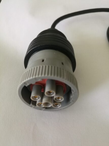
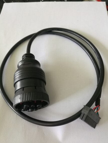
Heavy-Duty 9-Pin Industrial Diagnostic Cable Assembly
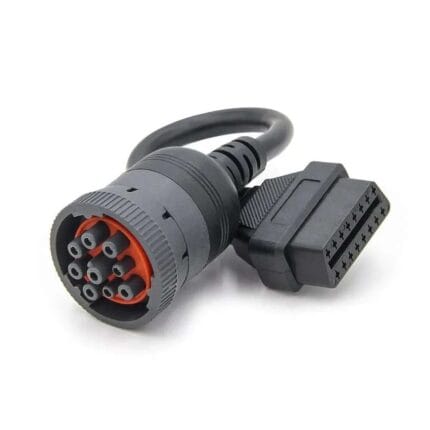
A heavy duty 9 pin cable with a 9-pin round industrial plug and a 14-pin 2x7 DIP bare end, for engine management diagnostics on trucks, marine diesel and heavy equipment benches. Verify the pinout against your service manual, since 9-pin assignments follow the engine maker rather than one specification.