
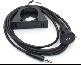
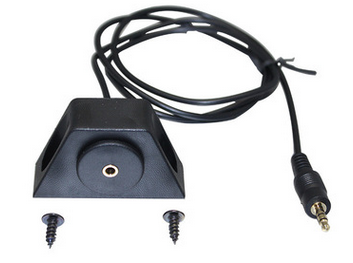
3.5 mm AUX Audio Female Panel Mount Extension Cable with Bracket
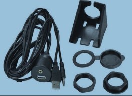
An aux audio cable with a 3.5 mm stereo socket on a flush panel bracket, so a phone or player plugs into the dash instead of the head unit. 4C x 28 AWG, OD 3.5 mm, gold or nickel contacts, black PVC jacket, 1 m / 2 m / 3 m.
Overview
An aux audio cable with a panel socket solves a problem that has nothing to do with sound quality and everything to do with ergonomics: the AUX input on the head unit is behind the trim, and nobody wants to plug into it directly. This build puts a 3.5 mm stereo female socket in a 28-30 mm round cut-out, held by a bracket and a screw nut from behind, and runs a 4-conductor 28 AWG lead back to the source. Gold or nickel-plated contacts, black PVC jacket at 3.5 mm OD, in 1 m, 2 m and 3 m. In a 4-conductor build like this one the spare conductor is normally tied to the sleeve at both ends, which halves the return resistance; if you want a microphone channel instead, the panel socket has to be a 4-pole TRRS part and that has to be on the order.
Key Specifications
| Connector A | 3.5 mm Stereo Male |
|---|---|
| Connector B | 3.5 mm Stereo Female, panel mount |
| Audio channels | Stereo left and right |
| Conductor | 4C x 28 AWG |
| Outer diameter | OD 3.5 mm |
| Contact plating | Gold plated / nickel plated |
| Jacket material | Black PVC |
| Cable length | 1 m / 2 m / 3 m |
| Mounting | Flush mount bracket, 28-30 mm cut-out, screw and cap |
| Application | Car, marine and motorcycle AUX input; furniture and desk ports |
The hum problem: where it comes from and how to kill it
Alternator whine and a buzz that rises with engine speed are the two complaints that follow every vehicle AUX install. Both are ground loop symptoms. The source device is referenced to one ground through its charger, the head unit is referenced to another, and because those two grounds are not at exactly the same potential, current flows in the shield of the audio cable and that current is amplified along with the music. Changing the cable does not fix it; breaking the loop does.
| Symptom | What it usually is | First thing to try | If that fails |
|---|---|---|---|
| Whine that tracks engine speed | Alternator ripple entering through a shared ground | Run the player on battery – if the noise stops, it is the charger | A ground loop isolator on the audio path |
| Steady buzz regardless of engine | Charger leakage into the audio ground | Try a different charger, ideally one with no earth reference | Isolate the shield at one end only |
| Noise when a phone is charging | Switch-mode charger noise on the 5 V rail | Charge from a different supply than the head unit | Separate the power and audio routes physically |
| One channel quiet or absent | Wrong plug seating or a broken conductor | Push the plug fully home and wiggle-test both ends | Continuity check pin to pin – this is a warranty call |
| Crackle when the plug is touched | Worn socket contacts or a bent tip | Replace the plug lead first, it is the cheap part | Replace the panel socket; check for a cracked flange |
Shield or no shield, and where to bond it
On a short unbalanced run inside a vehicle, a shield bonded at both ends is usually the wrong answer, because a second ground path is exactly what creates the loop you are trying to avoid. The conventional practice is to bond the shield at the source end and leave it floating at the receiving end, so it still drains the electric field but cannot carry ground current. If the run passes a motor, an inverter or a fuel pump, shield it; if it is a 1 m run from a console socket to a head unit, the twisting and the shared return matter more than the foil.
| Run | Recommended construction | Shield bonding | Why |
|---|---|---|---|
| Console socket to head unit, under 2 m | 4C x 28 AWG, shared return | One end, at the source | No second path, so no loop current |
| Run past a motor, inverter or DC-DC converter | Shielded pair construction | One end only | The drain takes the field, not the return |
| Long run to a rear amplifier | Heavier conductors, star ground at the amp | At the amplifier ground point | A single ground reference at the far end |
| Boat or motorcycle, exposed to spray | Sealed socket with a cap | Per the head unit grounding scheme | Corrosion is the real enemy, not noise |
Four conductors on a three-pole plug: what the spare wire is for
A 3.5 mm stereo plug has three contacts – tip, ring and sleeve – so a four-conductor cable has one conductor more than the connector strictly needs. The two sensible uses are to parallel the sleeve return, which lowers the return resistance and slightly improves crosstalk between channels, or to carry a microphone or a second ground for a TRRS headset. The second one changes the socket, so say it at order time rather than discovering it when the customer plugs in a headset and the microphone does not work.
Where an aux audio cable belongs in the build
- Car, marine and motorcycle dashboards where the AUX input has to be reachable from the seat
- Center consoles and glove boxes on fleet vehicles that still run legacy head units
- Furniture, conference tables and hotel-room multimedia panels with a flush 3.5 mm socket
- AV receiver and amplifier rear-panel hookups where the input is buried behind the rack
- Industrial control panels and kiosks that play an audio prompt, see our Kiosk and Self-Service Terminal Harness
- Retrofit panels that combine AUX with charging, see the Dual-Port USB 3.0 Panel Flush-Mount Extension
- Marine and medical carts where a serviceable panel socket beats a hidden input, see the Medical Panel Feedthrough Set
- Legacy AV installs that still carry a DIN or D-sub audio path, see the 8-Pin DIN Panel-Mount Extension
Failure modes on panel audio sockets
The mechanical one is a bracket screw done up far too tight: on a thin plastic trim panel that cracks the panel around the hole and the socket then works loose, so every plug insertion moves it. The electrical one is a cable tie pulled hard over the jacket close to the socket, which crushes the conductors and produces exactly the intermittent one-channel fault that is hardest to diagnose. The environmental one is a socket in a motorcycle or boat install left uncapped, where a season of spray leaves a green contact surface and a channel that comes and goes. Fit the cap, tie lightly, and snug – not tight – on the bracket nut.
How to specify your build
- Poles – 3-pole TRS stereo as standard, or 4-pole TRRS if you need a microphone.
- Cut-out – 28-30 mm round; confirm against the bracket drawing.
- Length – 1 m, 2 m or 3 m, or your measured route length.
- Shielding – unshielded as standard; shielded where the run passes a motor or inverter.
- Contact plating – gold or nickel, and whether the environment is damp.
- Cap – fitted, tethered, or open socket.
- Quantity and whether this is a prototype or a production order.
Workmanship and testing
Build standard for 3.5 mm AUX Audio builds is IPC/WHMA-A-620 Class 3 under ISO 9001, with terminations from 32 to 12 AWG. continuity and pinout are tested on each 3.5 unit before it is packed, and seal checking is quoted whenever an ingress rating is on the drawing.
Material declarations against RoHS and REACH are issued per project, alongside the dimensional and electrical reports agreed at quotation; see certifications, compliance and material declarations. Where your drawing names a UL style or another approval, the build follows your drawing and ships with the supporting document rather than a claim of our own. Termination, molding and verification happen in-house see the assembly lines behind this build so the process that made your sample is the process that runs the order. More background: engineering support and design for manufacture review. Tooling for this build is cut in our own tool room and belongs to your program, so a repeat run years later starts from the same tool.
Custom builds and ordering
On 3.5 mm AUX Audio builds, prototype lots run from 1 to 50 pcs and leave in 3 working days. Production runs of 500 pcs and up ship 14 working days after approval. Tooling not already held adds around 10 working days. 3.5 OEM and ODM shipments carry your part number and labeling, and we provide material certificates and first-article reports when asked.
Related audio and panel hardware
- 8-Pin DIN Male to Female Panel-Mount Extension
- Dual-Port USB 3.0 Panel Flush-Mount Extension
- Medical Panel Feedthrough Set for Cart and Monitor Arms
- Control Cabinet Service Interface with RJ45 and USB-C
- Coiled Retractable Cable for Instruments and Test Leads
Full ranges: panel mount cable, signal and data cables and custom wire harnesses.
Frequently Asked Questions
There is a whine that follows the engine. Is the cable faulty?
Almost never. That is a ground loop between the player and the head unit. Run the player on battery: if the noise stops, it is the charger, and a ground loop isolator or a different charger is the fix.
Can I have a microphone channel on the same socket?
Yes, but the panel socket has to be a 4-pole TRRS part instead of a 3-pole stereo socket. That has to be specified before we build, because it changes the connector.
Should the shield be connected at both ends?
Usually not. Bonding at both ends gives the loop current a path to flow in, which is the noise you are trying to remove. One end, at the source, is the normal answer on a short unbalanced run.
Gold or nickel contacts?
Gold resists corrosion better and is the right call in a damp or marine install. Nickel is perfectly serviceable in a dry cabin and costs less.
| Connector A | 3.5 mm Stereo Male |
|---|---|
| Connector B | 3.5 mm Stereo Female, panel mount |
| Cable length | 1 m / 2 m / 3 m |
| Audio channels | Stereo left and right |
| Conductor | 4C x 28 AWG |
| Outer diameter | OD 3.5 mm |
| Contact plating | Gold plated / nickel plated |
| Jacket material | Black PVC |
| Mounting | Flush mount bracket, 28-30 mm cut-out, screw and cap |
| Application | Car, marine and motorcycle AUX input; furniture and desk ports |
Related products
SPE Bulkhead Panel Connector for 10BASE-T1L Field Devices
An SPE bulkhead panel connector brings 10BASE-T1L single pair Ethernet and Power over Data Line into a field device box through one sealed penetration. IEC 63171-6 mating face or M8 coupling, front or rear mounting. The cut-out is smaller and the termination is faster than a four-pair Ethernet entry.