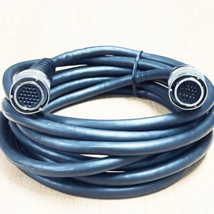
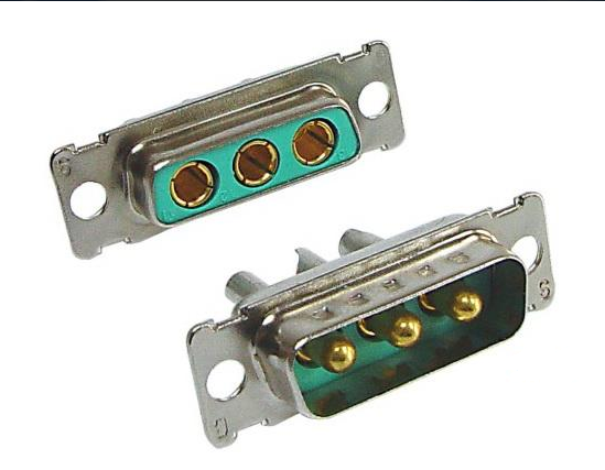
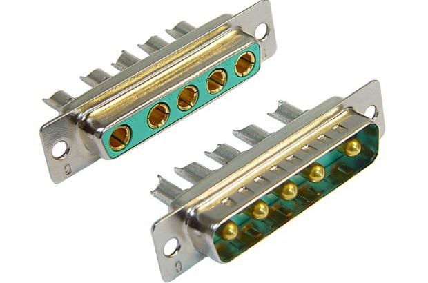
2V2 / 3W3 / 5W5 Mixed-Contact D-Sub Cable
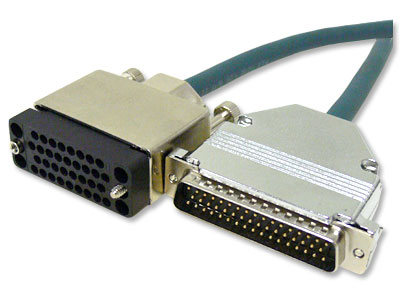
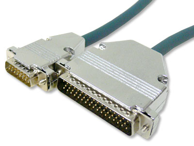
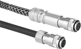
This mixed contact combo cable carries 2, 3 or 5 coaxial contacts in a 2V2, 3W3 or 5W5 D-Sub shell, in 50 ohm or 75 ohm RG-178 or RG-316 under foil and braid. Built to your contact count, gender, impedance and length for test fixtures, broadcast and aerospace panels.
Overview
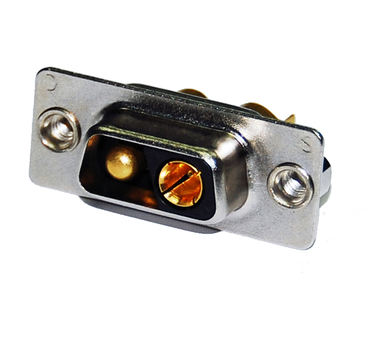
A mixed contact combo cable puts coaxial contacts into a D-Sub shell. The 2V2, 3W3 and 5W5 layouts carry two, three or five coaxial contacts in the standard D-Sub frame, which is why they turn up on test fixtures, broadcast patch panels and aerospace breakouts where the panel cut-out was designed years ago and is not going to change. Ours is two, three or five 50 ohm or 75 ohm miniature coaxial lines in RG-178 or RG-316, under an overall foil plus braid shield, in a PVC jacket, with metal hoods and thumbscrews. Contact count, impedance and length are set by your drawing.
Key Specifications
| Connector A | 2V2, 3W3 or 5W5 male, mixed contact, metal hood |
|---|---|
| Connector B | 2V2, 3W3, 5W5 or BNC breakout, per inquiry |
| Coaxial Impedance | 50 ohm or 75 ohm, per contact |
| Signal Conductors | Coaxial, RG-178 or RG-316 typical |
| Shielding | Overall foil + braid |
| Jacket | PVC, black, 6 mm to 10 mm OD |
| Length | 0.5 m to 5 m standard; OEM on request |
| Build | Built and verified to your drawing and contact layout |
Shell sizes on this mixed contact combo cable
The naming is cryptic but consistent: the number is the contact count and the letters describe what those contacts are. W means a coaxial (high-frequency) contact in a size 8 cavity, and the digit in front of it tells you how many. So 3W3 is three coax contacts in a shell the size of a DB25, with the remaining cavities unused or populated with signal pins depending on the build. What matters when you order is the shell size, the contact count and the gender, and the table below covers the three layouts we build most.
| Layout | Coax contacts | Matches shell size | Where you meet it |
|---|---|---|---|
| 2V2 | 2 coax | DB15-size frame | Compact RF breakouts, two-channel test fixtures |
| 3W3 | 3 coax | DB25-size frame | RGB video, three-channel RF patching |
| 5W5 | 5 coax | DB25-size frame | Five-channel RF and multi-way video breakouts |
| BNC breakout | 2, 3 or 5 | Flying BNC connectors | Where the far end is individual BNC jacks |
50 ohm or 75 ohm: which one is on your panel
This is the question that decides whether the assembly works, and it cannot be answered from the shell. 50 ohm is the RF and data convention – test equipment, radio, most coaxial instrumentation. 75 ohm is the video convention – analog video, broadcast, and anything with a BNC carrying a picture. Mixing them does not stop the signal, it degrades it: every impedance step is a reflection, and at video frequencies a reflection is a visible ghost. If the panel is legacy and undocumented, look at what is plugged into it today, or measure a known-good cable with an ohmmeter between center pin and shield. We build either, and we verify the impedance of the coax lines before the assembly is packed.
| Impedance | Convention | Typical use | If you get it wrong |
|---|---|---|---|
| 50 ohm | RF and data | Test instruments, radio, coaxial digital | Mismatch loss and reflections on an RF link |
| 75 ohm | Video | Broadcast, analog video, BNC picture feeds | Ghosting and level error on a video path |
What this cable is not for
These shells carry analog or RF signals over coax. They are not a digital signal carrier. If you are moving TMDS, USB 3.0 or Ethernet, use a cable built for that interface: a mixed-contact D-Sub has neither the controlled impedance nor the pair geometry a differential digital link needs, and the most common way these assemblies get mis-applied is someone inheriting a panel full of 3W3 connectors and assuming they can carry anything. They cannot. They carry what they were designed to carry, and they do it very well.
Contact termination: crimp or solder
Coaxial contacts for these shells come in both flavors, and the choice is usually made for you by the tooling you have. Crimp contacts are faster and more repeatable in production and are the default for a volume build. Solder contacts are what you want for a prototype, or where the contact is being reworked in the field by a technician with a soldering iron and no crimp tool. Either way the important part is the preparation: the braid has to be trimmed clean, the dielectric must not be nicked, and the center conductor has to be the right length in the contact. That is workmanship rather than materials, and it is what IPC/WHMA-A-620 Class 3 inspection is looking at on every unit.
Typical applications for this mixed contact combo cable
- Test fixtures and patch panels using mixed-contact D-Sub shells
- Broadcast studio video and audio patching
- Aerospace and high-frequency signal breakout
- Replacement cable for legacy 2V2, 3W3 or 5W5 chassis wiring
- BNC breakout leads where a multi-way shell feeds individual instruments
How to specify your build
- Shell size – 2V2, 3W3 or 5W5 – and the gender of each end.
- Impedance – 50 ohm or 75 ohm – confirmed, not assumed.
- Cable type – RG-178 or RG-316, or your specified coax.
- Far end – same shell, or a BNC breakout.
- Length and jacket color.
- Quantity, and whether this is a sample or a production order.
Workmanship and testing
2V2 / 3W3 / builds are assembled and inspected to IPC/WHMA-A-620 Class 3 criteria, with ISO 9001 as the quality system over 32 to 12 AWG work. continuity and pinout are checked on every 2V2 unit before packing, and seal checking is quoted whenever an ingress rating is on the drawing.
Material declarations against RoHS and REACH are issued per project, alongside the dimensional and electrical reports agreed at quotation; see certifications, compliance and material declarations. Where your drawing names a UL style or another approval, the build follows your drawing and ships with the supporting document rather than a claim of our own. The strain relief and molded body are produced on tooling we cut ourselves see overmold tooling cut in our own tool room so the tool is quoted separately, owned by you, and available for repeat runs years later. More background: cable assemblies for test and measurement.
Custom builds and ordering
2V2 / 3W3 / prototype builds start from 1 to 50 pcs and are out in 3 working days. Production is quoted from 500 pcs at 14 working days after approval. Tooling not already held adds around 10 working days. Private-label 2V2 runs ship under your part number and labeling, and material certificates and first-article reports can be supplied.
Related D-Sub and coaxial assemblies
- 13W3 to VGA (HD15) Mixed-Contact D-Sub Cable
- DB50 to DB25 DTE Serial Cable
- SCSI Cable Assembly, HD68 to HD68
- SMA to BNC RF Coax Patch Cable, 50 Ohm RG-58
- CoaXPress Machine Vision Cable Assembly
- LFH60 to DB37 RS-449 / V.35 DCE Serial Cable
Full range: signal and data cable assemblies.
Frequently Asked Questions
How do I know if my panel is 50 or 75 ohm?
Check what is plugged into it today, or measure a known-good cable between center pin and shield. The shell does not tell you.
Can I mix coax and signal contacts in one shell?
Yes. That is what a mixed-contact shell is for. Send the contact layout you need and we will populate accordingly.
Can this carry Ethernet or USB 3.0?
No. Use a cable built for that interface. These shells carry coaxial RF and video signals.
Do you supply the BNC breakout version?
Yes. A 2V2, 3W3 or 5W5 shell at one end and individual BNC connectors at the other is a common build.
| Connector A | 2V2, 3W3 or 5W5 male, mixed contact, metal hood |
|---|---|
| Connector B | 2V2, 3W3, 5W5 or BNC breakout, per inquiry |
| Coaxial Impedance | 50 ohm or 75 ohm, per contact |
| Signal Conductors | Coaxial, RG-178 or RG-316 typical |
| Jacket | PVC, black, 6 mm to 10 mm OD |
| Length | 0.5 m to 5 m standard; OEM on request |