Motoman Robot Teach Pendant Cable for DX100 / DX200 / FS100
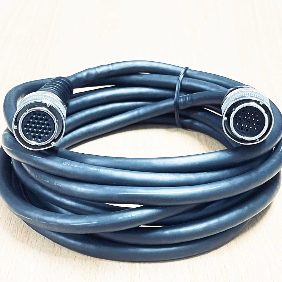
This motoman teach pendant cable is wired to the DX100, DX200 and FS100 controller pin layout, carrying pendant power, enable, serial data and the emergency stop loop. Eight 24 AWG shielded conductors in an oil-resistant PUR drag-chain jacket, built to your length and connector orientation.
Overview
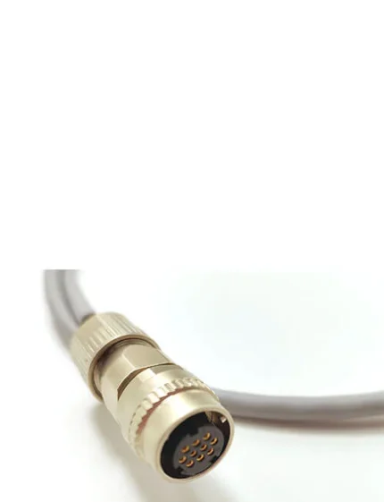
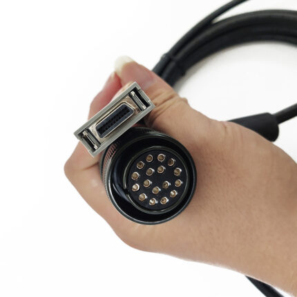
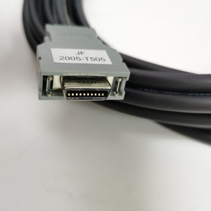
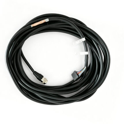
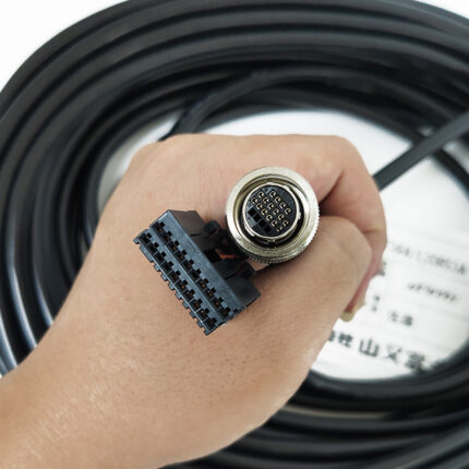
A motoman teach pendant cable carries everything the pendant needs to be a safe control point: pendant power, the enable circuit, serial data and the emergency stop loop. This one is wired to the DX100 / DX200 / FS100 controller pin layout, with eight 24 AWG stranded tinned copper conductors in a tight bundle under an overall foil plus braid shield and drain wire, in a halogen-free PUR jacket rated for drag-chain use. The pendant end is a Motoman-compatible locking rectangular shell; the controller end is the matching receptacle or an open lead with numbered ferrules. It is a compatible replacement, not an OEM Yaskawa Motoman product.
Key Specifications
| Connector A | Motoman teach pendant side, locking rectangular shell |
|---|---|
| Connector B | Controller side, DX100 / DX200 / FS100 receptacle or open lead |
| Cable | 8-core, 24 AWG stranded tinned copper |
| Shielding | Overall foil + braid, drain wire |
| Jacket | PUR, black, drag-chain rated, oil-resistant |
| Bend Radius | 10 x OD static, 7.5 x OD dynamic |
| Length | 5 m to 30 m standard; OEM on request |
| Build | Built and verified to your drawing and pinout |
What this motoman teach pendant cable carries
Eight conductors sounds like more than a pendant should need until you list the functions. Power and return take two. The enable device takes two more, and it is wired as a loop rather than a single line precisely so that an open circuit is detectable. The serial data pair needs a twisted pair and a real screen, because a pendant that drops its link mid-move is dangerous rather than merely inconvenient. The emergency stop loop takes the remainder, and it is the function that governs how we build the rest: the screen is bonded rather than pigtailed, and every conductor is continuity checked, so a degrading cable announces itself as a fault instead of as intermittent behavior.
| Function | Conductors | What it does |
|---|---|---|
| Pendant power | 2 cores | Powers the pendant logic and the display backlight |
| Enable circuit | 2 cores | Enables motion in teach mode; wired as a loop so an open is detectable |
| Serial data | Twisted pair | Pendant to controller comms; needs the screen intact |
| Emergency stop loop | 2 cores | Safety function; a cable fault must be a hard stop, not a glitch |
| Screen | Foil + braid + drain | Bonded at both ends so a broken braid shows up as a fault |
DX100, DX200 or FS100: does it matter which?
Yes, and mostly at the controller end. The pendant-side shell is the same family across the three, but the far end differs: some cabinets present a receptacle, others expect an open lead landed on terminals with numbered ferrules, and the length you need changes with where the pendant lives on the cell. Tell us the controller generation and how the far end terminates and the rest follows. If you are replacing an existing lead, a photo of both connector faces and the label on the controller is enough to identify it, and it removes the one variable that most often produces a wrong first article.
Why the pendant end fails before the controller end
The controller end sits still for years. The pendant end gets picked up, put down, dragged across the floor, hung on a hook and occasionally driven over. Every one of those events puts the same few centimeters of cable at the connector exit into a bend tighter than the jacket is rated for, and that is where the conductors work-harden and part. Two things extend the life, and neither is exotic: a longer strain-relief transition that spreads the bend, and a jacket compound that survives the coolant and oil the lead picks up off the floor. We mold both as part of the assembly rather than fitting a boot afterwards.
How to confirm the connector before you order
Pendant connectors are rectangular, locking, and easy to confuse with each other in a photograph taken at an angle. Three checks are enough: shell outline and keyway, latch position, and pin count visible on the face. If the old lead is still in one piece, send it – reading a sample is faster and cheaper than exchanging drawings.
| Check | How to capture it | What it rules out |
|---|---|---|
| Shell outline and keyway | Photo of the connector face, straight on, lit from the side | A mirrored or wrong-size shell |
| Latch position and type | Note whether it is a thumb latch or a slide | A housing that will not lock |
| Pin count on the face | Count the positions in the photo | An 8-position shell against a different pinout |
| Controller end termination | Receptacle, or open lead into the cabinet | A plug you cannot land |
| Routed length | From the controller to the furthest point the operator stands | A lead that pulls at the extreme |
Typical applications for this motoman teach pendant cable
- Teach pendant cable replacement on DX100 controllers
- Drop-in lead for the DX200 and FS100 controller family
- Yaskawa Motoman MH, MA and HP series robot teach pendants
- High-flex production cells using drag-chain cable tracks
- Spare-lead programs for cells that cannot take an unplanned stop
How to specify your build
- Controller generation – DX100, DX200 or FS100.
- Pendant model, from the label on the back of the pendant.
- Far end – receptacle or open lead with ferrules.
- Length, measured to the furthest point the operator stands.
- Connector orientation, straight or right-angle.
- Quantity, and whether this is a sample or a production order.
Workmanship and testing
Workmanship on Motoman Robot Teach Pendant builds follows IPC/WHMA-A-620 Class 3, the line is run under ISO 9001, and the termination range is 32 to 12 AWG. continuity and pinout are verified on each Motoman assembly before packing, and seal checking is quoted whenever an ingress rating is on the drawing.
RoHS and REACH declarations are provided per project together with the agreed test reports; the documentation scope is listed under certifications and compliance. If your drawing specifies a UL style, we build to that drawing and supply the UL reference with the shipment instead of substituting an equivalent. Flex life is a construction decision made before tooling, following the conductor and jacket approach set out under high-flex drag chain harness builds. Related reading: what instrument builds require. Any tooling we cut for this part stays yours, maintained in our own tool room under your part reference.
Custom builds and ordering
Quote Motoman Robot Teach Pendant builds from 1 to 50 pcs and they ship in 3 working days. At volume the minimum is 500 pcs with 14 working days after approval. Tooling not already held adds around 10 working days. Your part number and labeling go on Motoman shipments, and material certificates and first-article reports can be supplied.
Related robot and feedback assemblies
- Robot Teach Pendant Cable with PUR Jacket
- Robot Torsion Resistant Cable for Six-Axis Arms
- Custom Industrial Robot Wire Harness
- Cobot Arm Cable Harness with Drag-Chain Jacket
- Encoder Feedback Cable with PUR Jacket for Digital Drives
- Cleanroom Robot Cable Harness for EFEM and Vacuum Tools
Full range: signal and data cable assemblies.
Frequently Asked Questions
Is this an original Yaskawa Motoman part?
No. It is a compatible replacement wired to the DX100 / DX200 / FS100 pin layout and built to your drawing.
Can you build the controller end as an open lead?
Yes. Open ends come with numbered ferrules so the cabinet end lands directly on terminals.
What if my pendant has a different pinout?
We build to the pinout you send. Your drawing is the reference we verify each unit against.
How long can the lead be?
5 m to 30 m as standard. Give us the routed length to the furthest point the operator stands, not the straight-line distance.
| Connector A | Motoman teach pendant side, locking rectangular shell |
|---|---|
| Connector B | Controller side, DX100 / DX200 / FS100 receptacle or open lead |
| Cable | 8-core, 24 AWG stranded tinned copper |
| Shielding | Overall foil + braid, drain wire |
| Jacket | PUR, black, drag-chain rated, oil-resistant |
| Bend Radius | 10 x OD static, 7.5 x OD dynamic |
| Length | 5 m to 30 m standard; OEM on request |