MJ32 3-Pin Push-Pull Quick-Lock Cable
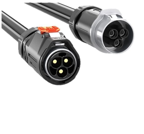
A MJ32 3 pin push pull quick lock cable is a build-to-print assembly joining a male pin plug to a female panel mount receptacle through a push-pull self-latching coupling. The MJ32 series is supplied in a 3-position layout, with the pinout, cable length, jacket and rear seal set on the approved drawing. Connector supplier ingress ratings apply in the mated condition; the finished assembly IP class, all electrical ratings and pricing are confirm per build or confirm per RFQ.
Overview
A MJ32 3 pin push pull quick lock cable is a build-to-print cable assembly that joins a male pin plug to a female panel mount receptacle through a push-pull self-latching coupling. We supply the interconnect: the connector pair, the jacketed lead, the rear strain relief and the terminations on the pinout you provide. The 3-position MJ32 shell is selected for three-position duty, and the panel cut-out, contact arrangement, cable length and jacket are all fixed on the approved drawing. Electrical ratings, ingress class of the finished assembly and all pricing are confirm per build or confirm per RFQ; this page publishes no catalog rating and no approval claim.
Read the MJ32 3 pin push pull quick lock cable as a construction description rather than a fixed part number. Two assemblies built on the same shell can differ in gender, keying, pinout, jacket, length and rear sealing, and each of those changes what ships. The sections below explain the coupling, the sealing paths and the items we need from you to quote.
What the MJ32 3-Pin Push-Pull Quick-Lock Cable Includes
Four elements are joined in one build: a circular plug with its contact insert, a mating panel receptacle with a gasket and jam nut, a jacketed multiconductor cable, and a rear transition that carries strain from the flexible lead into the rigid housing. On the panel side, the receptacle is fixed to the enclosure so the internal harness is not disturbed when the field plug is disconnected. On the cable side, the conductors are terminated to the contact positions shown on the drawing, and the exit is captured by a backshell or an overmold so a pull on the lead loads the jacket rather than the individual terminations.
We work from a sample or a drawing. Where a receptacle already exists in your equipment, we match the series, contact count, gender and keying to it; where the equipment is new, we take those items from the connector datasheet you specify. No brand name is claimed for the finished lead, and no electrical or ingress value is asserted without a corresponding document. Optional features such as a right-angle exit, a different jacket compound or a dust cap are quoted rather than assumed, confirm per RFQ.
MJ32 Series Shell Sizes and Contact Counts
The three-position MJ32 variant keeps the larger power shell while adding a third conductor for control, sense or earth duty. It is not a signal connector with a bigger body; contact geometry, cable outer diameter and termination differ from the smaller MJ series members. Series designations track shell and panel cut-out, so mating parts must be from the same family. All electrical limits come from the connector datasheet and are confirm per build.
Contact count is the other half of the selection. A 3-position insert is not a subset of a larger insert that can be reworked in the field; the insert, the shell and the keying are one matched set. If a design might grow to more conductors later, decide the shell at the layout stage, because the panel cut-out is expensive to change after machining. We also quote inline cable-to-cable versions where no panel is involved; that changes the receptacle to a cable-mounted female body and is quoted separately, confirm per build.
How the Push-Pull Quick-Lock Works
The coupling is a self-latching mechanism: pushing the plug home engages a spring latch, and pulling the outer sleeve withdraws it. There is no thread to cross, no torque value to hit and no bayonet twist, so mating is quick even with gloves or when the connector sits behind other fittings. The latch resists accidental release from vibration or a straight pull on the cable, which is why this coupling is common on instruments and serviceable equipment. It is not a substitute for correct installation, though; a plug that is not fully seated cannot seal or carry its rated load.
Our connector locking mechanism selection guide compares push-pull, threaded, bayonet and screw-retained couplings. For this build, the relevant checks are that the keying matches, that the latch clicks into place and that the cable has a strain relief before it leaves the housing. Mating cycle life and retention force are properties of the selected connector and are confirm per build from its datasheet.
Reference Build and Items Confirmed per Build
The table below is the configuration we quote from, not a fixed catalog part. It deliberately leaves electrical values, dimensions and approvals open, because those come from the connector datasheet and the equipment design. Anything not listed is quoted rather than assumed.
| Item | Reference configuration |
|---|---|
| Connector series | MJ32 push-pull circular connector family |
| Contact positions | 3 positions; arrangement confirm per build |
| Coupling | Push-pull quick lock, self-latching |
| Configuration | Male pin plug to female panel mount receptacle; inline cable-to-cable quoted separately |
| Contact gender and keying | Set on the approved drawing; confirm per build |
| Panel cut-out | From the connector datasheet for the selected series; confirm per build |
| Panel seal | Gasket at the receptacle-to-panel interface |
| Rear cable entry | Backshell plus optional adhesive-lined heat-shrink sleeve; confirm per build |
| Ingress rating | Connector supplier rating applies in the mated condition; finished assembly IP class confirm per build |
| Conductor and jacket | Stranded copper; PVC, PUR or TPE jacket; confirm per build |
| Cable length and exit | Cut to the drawing, straight or right-angle; confirm per build |
| Electrical rating | Set from the connector datasheet on the approved drawing; confirm per build |
| Test plan | 100% continuity, pinout and insulation check; limits confirm per build |
| Order quantity | Prototype 1-50 pieces; volume from 500 pieces; confirm per RFQ |
Ingress Protection and the Mated Condition
Public connector specifications for this family list IP67 in the mated condition, stated against IEC 60529 as a temporary-immersion test. Some published variants of the series are listed differently, so the exact class for your connector pair is taken from its datasheet rather than from a product page. That rating belongs to the connector pair: it describes a plug and receptacle that are correctly mated and latched. It does not automatically become a rating of our finished cable assembly, which adds a panel cut-out, a gasket compression, a cable outer diameter and a rear cable-entry seal. Ingress protection of the finished assembly is therefore confirmed per build in the mated condition.
There is a second distinction worth stating plainly. The jet-spray class and the temporary-immersion class are separate tests: the second characteristic digit above six is not a simple greater-than scale, so passing one does not stand in for the other. If your equipment must withstand a directed water jet, say so on the drawing and the test plan is set accordingly. We do not mark the finished lead with an ingress class or an approval claim, and we do not copy current, voltage or cycle figures from public listings.
What makes the biggest practical difference is a test report on the whole installed assembly: the same connector pair, the same cable outer diameter and the same rear sealing process that will ship. A report of that kind settles a buyer’s question faster than any number of qualifying sentences. Until such a report exists for a given build, the conservative wording above is what we use.
Panel Interface, Gasket and Rear Cable Entry
A sealed connection is a chain of separate seal points, and a failure at any one of them defeats the rest. The red gasket visible on a panel receptacle seals the receptacle to the enclosure only. The interfacial seal between plug and receptacle, the backshell to cable jacket transition, the dust cap used when unmated and the blocking between conductor strands are independent items. The table separates them.
| Seal point | Component | What controls it |
|---|---|---|
| Receptacle to panel | Panel gasket and jam nut | Cut-out size, panel thickness, compression, torque |
| Plug to receptacle | Interfacial seal at the mating face | Fully mated and latched; correct keying |
| Backshell to cable jacket | Adhesive-lined sleeve or gland | Shrink ratio, overlap length, clean jacket, visible adhesive at both ends |
| Open unmated port | Dust cap | Fitted whenever the connector is disconnected |
| Between conductors | Blocked or potted cable construction | Cable construction and potting, confirm per build |
Where a sleeve is fitted over the connector-to-cable transition, an adhesive-lined dual-wall tube can act as strain relief and as a cable-entry seal: the inner adhesive melts and fills the gap during shrinking. A plain single-wall tube provides abrasion protection and strain relief but little sealing. Either way, the tube has no ingress class of its own; the combination of tube, cable outer diameter and shrink process is what a test would cover. Our sealing and torque notes cover the installation side in more detail, and the overmolded assembly guide explains the one-piece alternative.
Pinout, Conductors and Jacket Options
We ask for a pinout table rather than a verbal description. For each contact position, state the signal or power function, the wire color or marker, the gauge and whether a shield is terminated to the shell or to a dedicated position. Mixed duty in one connector is common, but the equipment designer must confirm that the chosen contact geometry and creepage distances suit it; we do not make that judgment on your behalf. Polarity and keying are recorded on the approved drawing before any tooling or cutting starts.
Jacket compound is chosen for the installed environment: PVC for general cabinet wiring, PUR where abrasion and flexing dominate, TPE where a softer hand or a wider temperature window is needed. Flame, halogen and smoke requirements are specified per build with their test documentation, not claimed generically. Cable outer diameter must be within the range the selected backshell and any rear sleeve can seal, so it is checked against the connector datasheet at the quoting stage. Length, exit direction and any right-angle requirement are confirm per RFQ.
Typical Applications
Power plus pilot or earth conductors. Three contacts give a power pair and an additional pilot, sense or earth conductor in one latched interface. That combination appears on drive and distribution equipment where a control or monitoring lead has to follow the same path as the supply. The function of the third contact is equipment-specific, so we take it from the schematic; we do not assume it is a protective earth. Contact assignment, wire gauge and rating are confirm per build.
Three-phase or split-feed subassemblies. Some cabinets bring a three-conductor feed out through one panel opening to keep the harness simple. Whether that feed is three phases, two conductors plus earth, or a supply plus two control lines changes the connector selection and the cable construction, so the drawing must state it. Our scope is the interconnect and its strain relief, not the system electrical design. Polarity, keying and mating cycles are confirm per build.
Outdoor and marine-adjacent enclosures. Where the connection sees weather or washdown, a gasketed panel receptacle and a sealed rear cable entry are specified together with the plug. An adhesive-lined heat-shrink sleeve can be fitted over the connector-to-cable transition, but it does not replace the interfacial seal or the panel gasket. The connector supplier’s published ingress rating applies in the mated condition; the class achieved by the finished cable assembly depends on installation and is confirm per build. Material choice for salt or UV exposure is confirm per RFQ.
These are application contexts for the interconnect, not claims about the equipment that uses it. We build cable assemblies; we do not design the machine, and we do not certify the finished system. If your application carries a specific approval, environmental or documentation requirement, put it in the RFQ so the quotation and the test plan cover it, confirm per build.
Installation and Handling Notes
Machine the panel cut-out to the connector datasheet value for the exact series and part, then deburr and clean the mating face before fitting the gasket. Compress the gasket evenly with the jam nut; an uneven panel or an over-tightened nut can distort the seal. Route the cable so a service loop, not the termination, takes any pull, and keep the minimum bend radius of the chosen jacket in mind when the cabinet is closed. Fit the dust cap whenever the connector is unmated.
When a heat-shrink sleeve is used at the rear entry, clean the jacket, match the shrink ratio to the largest and smallest substrate, allow enough overlap and heat evenly until adhesive is visible at both ends. Overheating can damage the jacket and underheating leaves the adhesive inactive; either condition breaks the very seal the sleeve was meant to provide. These are process controls we put in the work instructions for the build, confirm per build.
Custom Builds and Ordering
Prototype quantities of 1-50 pieces are quoted for fit checks and field trials; volume production starts from 500 pieces. Both are built to the same approved drawing, and a sample from an existing harness is the fastest way to fix the pinout and the physical details. We have built more than 3,000 tooling sets since 2012 and keep over 100 active molds, so many exit geometries and overmold shapes can be reused; whether an existing tool fits your series is confirm per RFQ.
The RFQ preparation guide lists what to send. Open a written quote through the RFQ form. Prices, lead times and any minimum order variation are confirm per RFQ; this site does not publish a price list.
Quality, Testing and Compliance
Every assembly is checked for continuity, pinout correctness and insulation before it leaves the bench, with the pass limits set on the approved drawing. Where the drawing calls for a specific environmental test, the test is quoted and documented for that build rather than asserted from the connector datasheet. Material declarations, flame ratings and any third-party approval documents are available on request when they apply to the components actually used, confirm per build.
We keep the distinction between component data and assembly claims explicit. A connector supplier datasheet supports statements about that connector; it does not by itself support a statement about our finished cable. If a buyer needs a particular certificate or test report for the whole assembly, that requirement is agreed before production so the documentation matches what ships.
Frequently Asked Questions
What does the quick-lock coupling do?
The plug pushes straight into the receptacle and latches without a torque tool. Pulling the outer sleeve releases the latch. It gives a repeatable engaged state on panels that are connected and disconnected often, and it avoids the clearance a threaded coupling needs.
Can I mix parts from different MJ series?
No. Series designations in this family track shell and panel cut-out size, and the contact inserts differ. Specify the series, contact count, gender and keying together on the drawing, and check the cut-out against the connector datasheet before machining the panel.
Is the finished cable rated IP67?
The connector supplier publishes an ingress rating for the connectors in the mated condition. That is a rating of the connector pair, not of our finished cable assembly. The class achieved by the assembled lead depends on the mated condition, panel cut-out, gasket compression, cable outer diameter and rear cable-entry seal, and is confirmed per build.
What do you need to quote this cable?
Send the connector series and contact count, the pinout or schematic, the plug and receptacle gender, the cable length and jacket, the panel cut-out if the receptacle is already chosen, and the target quantity. A sample or an existing drawing is the fastest route. All electrical ratings and lead times are confirm per RFQ.
Related Cable Ranges
This build sits in our Panel Mount Cables range. For multi-conductor signal work see Signal and Data Cables, for branched builds to a drawing see Custom Wire Harnesses, and for center-screw retained molded connectors see Screw-Lock Molded Cables. Related push-pull builds already on the site include the DC waterproof push-pull quick-lock cable, the M16 DC push-pull quick-lock cable and the RJ45 push-pull quick-lock cable. Panel cut-outs and mounting are covered in how to select a panel mount connector. Send your drawing through the RFQ form.
| Connector series | MJ32 push-pull circular connector family |
|---|---|
| Contact positions | 3 positions; arrangement confirm per build |
| Coupling | Push-pull quick lock, self-latching |
| Configuration | Male pin plug to female panel mount receptacle; inline cable-to-cable quoted separately |
| Contact gender and keying | Set on the approved drawing; confirm per build |
| Panel cut-out | From the connector datasheet for the selected series; confirm per build |
| Panel seal | Gasket at the receptacle-to-panel interface |
| Rear cable entry | Backshell plus optional adhesive-lined heat-shrink sleeve; confirm per build |
| Ingress rating | Connector supplier rating applies in the mated condition; finished assembly IP class confirm per build |
| Conductor and jacket | Stranded copper; PVC, PUR or TPE jacket; confirm per build |
| Cable length and exit | Cut to the drawing, straight or right-angle; confirm per build |
| Electrical rating | Set from the connector datasheet on the approved drawing; confirm per build |
| Test plan | 100% continuity, pinout and insulation check; limits confirm per build |
| Order quantity | Prototype 1-50 pieces; volume from 500 pieces; confirm per RFQ |