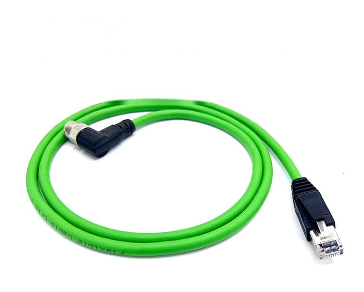
IP67 Right-Angle M12 D-Code 4-Pin Industrial Ethernet Cable
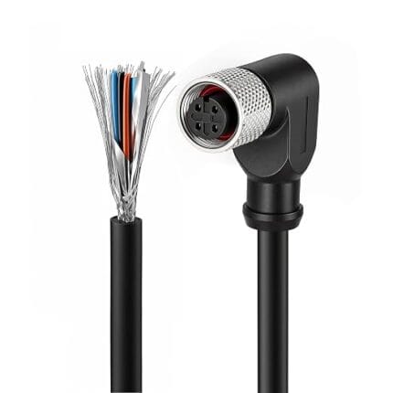
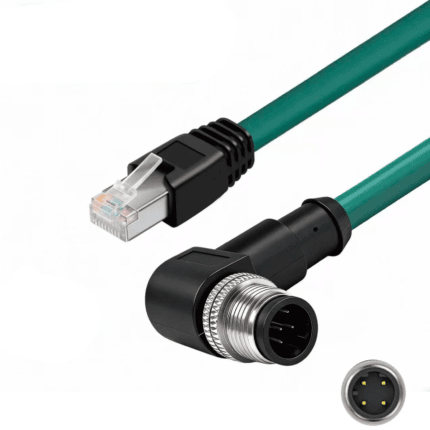
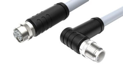
This IP67 right angle m12 d-code cable brings a 90-degree, 4-position D-coded M12 connector to machine vision cameras, switches and other PROFINET endpoints where a straight overmold would bend the cable too sharply at the port.
Overview
This IP67 right angle m12 d-code cable brings a 90-degree, 4-position D-coded M12 connector to machine vision cameras, switches and other PROFINET endpoints where a straight overmold would bend the cable too sharply at the port.
The 4-position D-coded contact layout carries a single 100 Mbit/s industrial Ethernet channel, which is the configuration PROFINET and many industrial camera platforms specify for real-time I/O and image traffic. Because the connector housing turns the cable ninety degrees, the cordset sits flush against camera housings, junction boxes and control cabinets whose ports face a wall, a bracket or another connector.
Key Specifications
The table below lists the configuration shown in the product photo.
What D-Coding Buys You
D-coding is the four-position Ethernet member of the M12 family, defined in IEC 61076-2-101 alongside A, B and C coding, and rated for 100 Mbit/s industrial networks. Its two shielded pairs carry one channel of Fast Ethernet, which is exactly the transport class PROFINET RT and EtherNet/IP device-level rings run on.
The value of keeping Ethernet on a circular connector rather than an RJ45 is environmental. A standard RJ45 relies on a plastic latch and leaves the port open to dust; a D-coded M12 joint screws together, seals against the mating face, and survives vibration without working loose. On a machine that is washed down or mounted on moving equipment, that difference determines whether the network stays up.
D-Code Versus X-Code: Not Interchangeable
The M12 Ethernet family has two members and they are not compatible with each other. D-code has four contacts and handles 100 Mbit/s. X-code has eight contacts, a different keyway and a different insulator geometry, and handles gigabit and ten-gigabit industrial Ethernet.
They do not mate, and substituting one for the other is a common purchasing error because both are described simply as “M12 Ethernet”. Check the device datasheet for the coding letter: a camera specified with a D-coded port needs a D-coded cordset, and no amount of adapter stacking is a good answer on a machine that vibrates.
Why the Right-Angle Version Exists
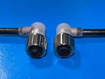
Clearance is nearly always the reason this version gets specified. Industrial cameras are typically mounted on a bracket with the port facing sideways; the space between that port and whatever the camera is bolted to is often a few centimeters. A straight M12 body plus its required bend radius needs more than that, so either the cable gets bent past its minimum radius or the camera has to move.
The right-angle body puts the turn inside the molded shell. The cable then runs along the mounting face instead of projecting from it, which also means the whole assembly can sit inside an enclosure whose depth was never designed around the connector.
Shielding and Where to Ground It
D-coded Ethernet expects screened cable, and this build uses shielded twisted pairs under an overall screen. The pairs stop crosstalk between transmit and receive; the screen stops external noise from reaching them, which matters because industrial Ethernet runs sit next to motor leads, contactors and variable-frequency drive outputs.
Good shielding that is grounded badly is worse than none, because it becomes an antenna at one end. Follow the grounding practice your network specification calls for, keep the drain short at the point where it lands, and avoid creating a path that lets the screen carry current between two grounds at different potentials.
Construction and Materials
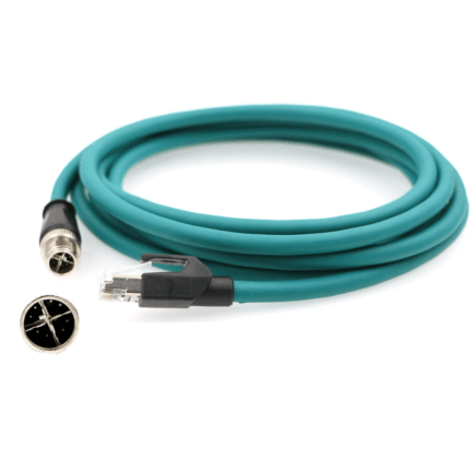
The M12 end is molded directly onto a green circular jacket, and the threaded metal coupling nut is knurled so technicians can finger-tighten it in enclosed spaces. Inside, the four contacts land on twisted pairs with an overall shield, matching the screened wiring that D-coded Ethernet ports expect. The opposite end is a standard RJ45 plug with a strain-relief boot, so the cordset runs from any conventional Ethernet port straight into the sealed M12 field connection.
Sealing only exists across a mated pair. The IP67 rating describes the joint when the two halves are coupled and correctly tightened — an unmated plug left open on a machine is not protected by anything.
Typical Applications
Typical mounts include industrial area-scan and line-scan cameras, IO-Link masters with Ethernet uplinks, compact switches mounted on DIN rail close to a cabinet wall, and any PROFINET device installed with its port facing a mounting surface. The right-angle exit also shortens the clearance a service loop needs behind the device, which helps in shallow enclosures.
Machine vision is the biggest user of this exact form. Area and line-scan cameras are bolted into tight guarding, and their Ethernet port almost always points somewhere inconvenient.
Vision-guided robot cells add motion to the problem. The camera moves with the cell, the cable has a defined path, and anything standing proud of the housing risks being caught.
Remote I/O blocks and DIN-rail switches in shallow cabinets round out the list — situations where the port sits within a few centimeters of a surface and there is simply nowhere for a straight body to go.
Where the RJ45 End Belongs
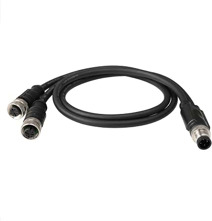
This cordset is a hybrid by nature: sealed circular at one end, office-standard RJ45 at the other. That is the right arrangement when one side sits in a protected cabinet. The RJ45 plugs into ordinary structured cabling or a switch, and only the field end needs to be sealed.
It is the wrong arrangement when both ends are outdoors or in a washdown zone, because the office-standard end becomes the weak link. In that case use a cordset that is sealed at both ends, or put the RJ45 inside an enclosure.
Compatibility and Fitment
The connector follows the D-coded keyway defined in IEC 61076-2-101, so it mates with standard D-coded M12 ports regardless of manufacturer. The RJ45 end works with ordinary Cat5e and Cat6 structured cabling ports. Confirm the port gender on your device before ordering: this assembly presents a female M12 field side and is commonly used where the device carries male D-coded contacts.
Where both ends of the run terminate in a cabinet rather than out in the field, an screened RJ45 patch lead is usually the simpler answer than a sealed cordset.
Installation Notes
Decide the exit direction when ordering. Because the body is molded, the direction the cable leaves is fixed relative to the keyway and cannot be rotated in the field.
Respect the minimum bend radius at the RJ45 end too. Both ends of a cordset get ruined by the same handling.
Keep the coupling firm but hand-tight. Overtightening with tools deforms the seal rather than improving it.
Custom Builds and Ordering
Length, jacket material and labeling can be specified when you order. If your drawing calls for a different exit direction, additional shielding classes or a special overmold shape, send us the sketch and target quantity and we will quote tooling and lead time. Prototype and sample lots run from 1 to 50 pieces; production orders start at 500 pieces per part number.
Packaging and Shipping
Each cordset is bagged with a labeled dust cap on the M12 interface, then packed in a protective carton. Bulk packaging on reels or in individual boxes is available for OEM volumes.
Quality and Compliance
Assemblies are tested for continuity and shield integrity before shipment, and the molding process is checked for full encapsulation around the connector shell. See the IEC 61076-2-101 circular connector standard for the governing interface specification.
Material declarations against RoHS and REACH are issued per project, alongside the dimensional and electrical reports agreed at quotation; see certifications, compliance and material declarations. Where your drawing names a UL style or another approval, the build follows your drawing and ships with the supporting document rather than a claim of our own. The 90-degree exit is formed in the tool itself; the exit options and their clearances are set out under right-angle exit tooling options. The wider context is covered under cable assemblies for industrial automation and robotics. Tooling for this build is cut in our own tool room and belongs to your program, so a repeat run years later starts from the same tool.
Frequently Asked Questions
Is this a gigabit cordset? No. D-coding carries 100 Mbit/s; gigabit and above belong to X-coded eight-position parts.
Can the exit angle be swapped after purchase? No. Orientation is set in the molding step, so specify it with the order.
Will the RJ45 end fit a standard switch? Yes. It is an ordinary RJ45 plug and mates with conventional structured cabling ports.
Is the connection sealed when unplugged? No. IP67 describes the mated pair; cap any open branch.
Related Cable Ranges
Browse the related ranges: Circular M-Series Cable Assemblies Ethernet Patch Cords Signal and Data Cables.
Compare the straight-coupling version in the M12 D-code to RJ45 screw-lock cable, or if neither end sees the outdoors consider an RJ45 screw-lock patch cable.
| Connector A | M12 D-coded, 4-position, female, right angle |
|---|---|
| Connector B | RJ45 plug, straight |
| Coding | D-coded, keyed to IEC 61076-2-101 |
| Application | Industrial Ethernet, PROFINET, machine vision |
| Shielding | Shielded twisted pairs |
| Ingress Rating | IP67 when mated |
| Orientation | 90-degree right angle at the M12 end |
| Jacket Color | Green |