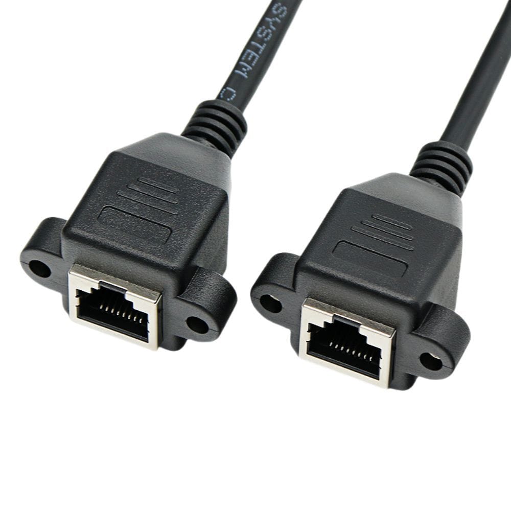
Cat6A RJ45 Screw-Lock Patch Cable, Both Ends Thumbscrew
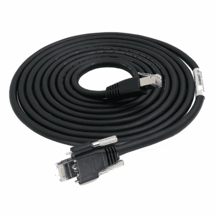
An RJ45 screw lock patch cable with thumbscrew locking on both plugs turns an Ethernet drop into a mechanically fixed connection, which is what you want when the two devices do not sit still relative to each other. Shielded S/FTP build, PoE capable, made to your length.
Overview
An RJ45 screw lock patch cable carries thumbscrew locking on both plugs, so an Ethernet drop stops being a friction-fit connection and becomes a mechanically fixed one. That is what you want when the two devices do not sit still relative to each other: a camera on a moving bracket, a switch inside a cabinet mounted on a press, a control box on an AGV. The cordset is shielded S/FTP with 26 AWG stranded bare copper, so the locking arrangement costs nothing in bandwidth, and it carries Power over Ethernet across all four pairs. The category your build is marked to is confirmed on the order – see the note below.
Key Specifications
| Connector A | RJ45 8P8C male with twin thumbscrew lock |
|---|---|
| Connector B | RJ45 8P8C male with twin thumbscrew lock |
| Locking Hardware | 4-40 UNC thumbscrews, horizontal or vertical orientation |
| Category | ISO/IEC 11801 Class EA / TIA-568.2-D Category 6A |
| Data Rate | 10GBASE-T to 500 MHz, IEEE 802.3an |
| PoE | Supports IEEE 802.3af, 802.3at and 802.3bt over 4 pairs |
| Conductor | 26 AWG stranded bare copper, S/FTP |
| Jacket | PVC standard; PUR or TPE on request |
| Mating Cycles | 750 minimum, IEC 60603-7 series connector rating |
| Length | OEM build to required length |
Which category does this plug actually say?
Ask, because this listing inherited inconsistent markings: the page address reads Category 6A, the product name reads Category 5, and the two appear in different places in the legacy copy. Rather than guess, we build to the category you state on the order and print it on the jacket. So when you enquire, tell us which one you need – Cat5e, Cat6 or Cat6A – and the plug, the cable print and the test sheet will all carry that marking. The mechanical build is the same; what changes is the cable construction, the frequency the assembly is verified to, and the channel budget it consumes. If you are matching an existing installation, send a photograph of the jack or the plug print and we will match it.
Shielded or unshielded: what S/FTP buys you here
| Construction | What it is | EMC behavior next to drives and weld power | When to specify it |
|---|---|---|---|
| UTP | Four pairs, no screen | Relies on pair twist alone; alien crosstalk rises in bundles | Office drops in clean electrical environments |
| F/UTP | One overall foil, no per-pair screen | Good against external noise, weaker between pairs inside the cable | General industrial runs where cost matters |
| S/FTP | Foil on each pair plus overall tinned copper braid | Best of the three for both internal crosstalk and external noise | Machine enclosures, camera links, anything near variable-frequency drives |
| SF/UTP | Braid plus foil over unscreened pairs | Strong against external noise, pairs still couple to each other | A cost compromise that rarely makes sense on a short machine run |
This build is S/FTP: each of the four pairs is wrapped in aluminum foil and a tinned copper braid covers the whole core. The metal connector shells bond to the braid at both ends so the screen stays continuous through the plugs instead of stopping at the crimp. A screen that is not terminated at both ends is decoration, so check that the equipment side actually provides a shielded receptacle – if it does not, the shield has nowhere to drain to.
How an extension eats your channel length budget
Structured cabling sets a channel limit, and that limit is shared between the permanent link in the wall and the patch cords plugged into each end. Adding an extension does not add length allowance; it spends the allowance you already had. The figures below are the industry-standard channel model, and the numbers your job is built to are the ones on your drawing.
| Part of the channel | Industry-standard model | What an extension does to it |
|---|---|---|
| Permanent link | Up to 90 m as defined in the ISO/IEC and TIA channel model | Not affected – it is already in the wall |
| Patch cords, both ends combined | Up to 10 m in the same model | Every extension you add comes out of this allowance |
| Total channel | 100 m including cords | Go over it and the link does not negotiate, or negotiates down |
| PoE reach | Set by the Ethernet distance limit, not by the power supply | A longer run means more voltage drop and more heat in the bundle |
Locking both ends: when it is worth it
- Both devices are on structure that moves or vibrates – a press, a gantry, a vehicle body, an AGV deck.
- The run is inside a machine and only reachable at service, so a plug that has walked out is a stoppage, not a five-second fix.
- The equipment is moved or re-configured between production runs.
- The receptacles are upside down or facing down, where a latch tab takes the whole weight of the cord.
The thumbscrews are captive in the molded shell so they cannot be lost during installation, and the orientation – horizontal or vertical – is specified to suit the receptacle layout on your equipment. Thread is 4-40 UNC, which is what industrial camera and vision receptacles use.
Power over Ethernet on the same cord
The assembly supports IEEE 802.3af, 802.3at and 802.3bt across four pairs, so the same cord that carries data feeds the device. Two things follow. First, all eight conductors are in play, so a cord with a missed pair is not a data problem alone. Second, current in every conductor generates heat, and bundled cords dissipate it badly: if you are running a dozen PoE devices through one tray, derate by routing, not by hope. Tell us the PoE class and the bundle size and we will size the conductor accordingly – the reference for the power levels is the Power over Ethernet family of IEEE amendments, and the values your build is verified to are the ones on your drawing.
Where an RJ45 screw lock patch cable is the right call
- Device-to-device Ethernet runs inside machines where both ends sit on vibrating structure
- Camera to switch links on packaging, printing and assembly equipment
- PoE powered devices – cameras, access points, readers, LED fixtures – that must not lose power when the machine shakes
- Extending a drop to a device that gets moved between cells, next to the right angle RJ45 screw lock cable where the plug has to leave sideways
- Temporary or semi-permanent installations in a cabinet that gets re-configured seasonally
Ordering and lead time
Five pieces is where a prototype starts and it ships in 3 working days. Production requires 500 pcs minimum and takes 14 working days after approval. Non-stock tooling adds around 10 working days. Private-label builds ship under your part number and labeling; material certificates and first-article reports are available on request.
Workmanship and testing
IPC/WHMA-A-620 Class 3 is the workmanship standard and ISO 9001 is the quality system behind it. We work from 32 to 12 AWG. Nothing ships without a continuity and pinout check, and seal checking can be added where an ingress rating is part of the specification.
Frequently Asked Questions
<div class="
For a related configuration, see the Right-Angle RJ45 Screw-Lock Cable (90 Degree Thumbscrew Plug, Cat6A S/FTP).
hkw-faq”>
Is this Cat5 or Cat6A?
Whichever you order. The legacy listing carries both markings in different places, so we build to the category you state and print it on the jacket and the plug. Send a photograph of the existing jack if you are matching an installed base.
Can I use a screw-lock cord with an ordinary unshielded jack?
Mechanically yes, but the screen then has nowhere to terminate and you lose most of the reason for specifying S/FTP. If one end lands on unshielded office equipment, tell us and we will quote the build accordingly.
Does a screw-lock extension really cost me channel length?
Yes. In the standard 100 m channel model the allowance for patch cords at both ends is 10 m, and every extension spends part of it. On machine runs this is rarely the binding constraint; on a drop fed from a distant cabinet it can be.
Why 26 AWG stranded rather than 23 AWG solid?
Stranded conductors survive being routed and re-routed inside an enclosure, which is where these cords live. Solid conductor belongs in the wall, not in a cord that gets dressed around a machine.
Related assemblies
| Connector A | RJ45 8P8C male with twin thumbscrew lock |
|---|---|
| Connector B | RJ45 8P8C male with twin thumbscrew lock |
| Locking Hardware | 4-40 UNC thumbscrews, horizontal or vertical orientation |
| Category | ISO/IEC 11801 Class EA / TIA-568.2-D Category 6A |
| Data Rate | 10GBASE-T to 500 MHz, IEEE 802.3an |
| PoE | Supports IEEE 802.3af, 802.3at and 802.3bt over 4 pairs |
| Conductor | 26 AWG stranded bare copper, S/FTP |
| Jacket | PVC standard; PUR or TPE on request |
| Mating Cycles | 750 minimum, IEC 60603-7 series connector rating |
| Length | OEM build to required length |