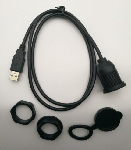
8-Pin DIN Male to Female Panel-Mount Extension Cable
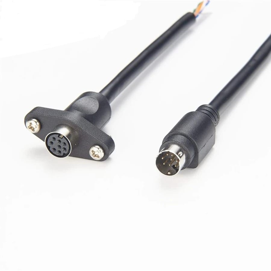
An 8 pin DIN panel mount cable that brings an 8-pin DIN socket out to a chassis or rack panel on a two-screw flange.
Last updated: 13 September 2026
Overview
An 8 pin DIN panel mount cable moves a connection from the back of a device to the surface of a cabinet. The free end is an 8-pin DIN plug for the equipment; the other end is an 8-pin DIN socket carried on a two-screw flange that drops into a panel cutout. Once it is fitted, patching happens at the front of the rack instead of behind it, and the socket on the equipment itself stops taking the wear.
Key Specifications
| Connector A | 8-pin DIN male |
|---|---|
| Connector B | 8-pin DIN female (panel mount) |
| Panel Mount | 2-screw flange |
| Shell | Standard 13.2 mm DIN body |
| Cable | Shielded multi-core, conductors to your pinout |
| Jacket | PVC |
| Strain Relief | Molded at the free end, clamped at the flange |
| Build standard | Built to the pinout you send; straight-through by default |
Which 8-pin DIN you have
The eight-pin shell is used for multi-channel audio, for control links and by a handful of manufacturers for power and data combined. There is no single pinout across all of them, so the shell gets you the mechanical fit and nothing else:
| Shell | Pin layout | Commonly used for | Check before ordering |
|---|---|---|---|
| 8-pin DIN, 270 degree | Outer ring of seven plus one center pin | Multi-channel audio and broadcast | Whether the center pin is used |
| 8-pin DIN, 180 degree | Two rows on an arc | Older consumer and industrial gear | Row spacing and keyway position |
| 8-pin mini-DIN | Smaller body, about 9.5 mm | Some data and power ports | Body diameter; it will not mate with standard DIN |
| 8-pin DIN on a panel | Same shell, flange mounted | Rack and enclosure feedthroughs | Cutout size and screw pitch |
These are industry-standard mechanical definitions for the DIN connector family. Your assembly is built and verified to the shell and pinout stated on your drawing.
Planning the panel cutout
- Cutout shape. An 8-pin DIN flange is round with a flat or a notch. Cut to the drawing, not by eye.
- Screw pitch. Measure center to center between the two fixing holes.
- Panel thickness. Sets the screw length and whether the flange sits flush.
- Depth behind the panel. The socket body plus the bend radius of the cable needs more room than it looks like on a drawing.
- De-burr the opening. A rough edge is what cracks a flange under tightening.
If you are fitting several, a patch panel layout with the ports labeled saves more time than any other part of the job.
Why the equipment socket fails instead of the cable
- Repeated re-patching at the back of a rack wears the socket on the device, which is soldered to the board and expensive to replace.
- Blind connection. Plugs get forced in at an angle when the operator cannot see the socket, and the pins bend.
- Cable weight hanging off a rear panel socket levers it until the joints crack.
- Dust and oxidation on a socket that is only used twice a year.
- Vibration in mobile racks working an unclamped plug loose.
Fitting a flange-mounted socket moves all of that wear onto a part you can replace in two minutes.
Fitting and verifying the panel mount
- Cut and de-burr the panel opening, then test-fit the flange before wiring anything.
- Fix the flange with both screws, evenly, without overtightening into a thin panel.
- Connect the free plug to the equipment with the power off.
- Confirm every conductor you need is present at the panel socket before you close the rack.
- Label the panel port. It takes ten seconds and saves an afternoon later.
Typical Applications for This 8 Pin DIN Panel Mount Cable
- Bringing a legacy multi-pin DIN port to the front of a rack
- Industrial control enclosures needing an operator-accessible connection
- Broadcast and studio patch panels built around multi-channel DIN
- Custom equipment where the original port sits somewhere inaccessible
- Mobile and touring racks where rear access is impossible once loaded
How to specify your build
- Shell and pin layout, from a photo of the connector face.
- Pinout, or a statement that straight-through is what you want.
- Flange style, screw pitch and panel cutout.
- Cable length from the equipment to the panel.
- Shielded or unshielded.
- Marking for the panel port if it is one of several.
- Quantity, and whether this is a prototype or a production order.
Workmanship and testing
Assembly and inspection follow IPC/WHMA-A-620 Class 3 workmanship criteria under our ISO 9001 quality management system, and every unit passes 100% continuity and pinout testing before it is packed. Conductor range is 32 to 12 AWG. Flange builds get a fit check against the stated cutout on the production batch. Any dimension quoted for the shell is the industry-standard value; your assembly is built and verified to your drawing.
Custom builds and ordering
Prototype builds start from 5 pcs and ship in 3 working days; production orders start at MOQ 500 pcs and ship 14 working days after approval. New flange tooling adds about 10 working days. OEM and ODM builds ship under your part number and labeling, with material certificates and first-article reports available on request. Factory audits and video line tours can be arranged.
Related panel mount and DIN assemblies
Putting a port on a panel usually means one of these alongside it:
- 6-Pin DIN Male to Male Dual Right-Angle Cable
- 5-Pin DIN Dual Right-Angle MIDI Audio Cable
- 4-Pin MIDI DIN Male to Female Extension Cable
- 3.5 mm AUX Audio Female Panel Mount Extension Cable
- Dual-Port USB 3.0 Panel Flush-Mount Extension Cable
- Control Cabinet Service Interface with RJ45 and USB-C Front Plate
- M12 Bulkhead Panel Connector with Pigtail
Full range: panel mount cable assemblies.
Questions Before You Order
Does the flange come with the cutout dimension?
Yes, per body style. Send your panel drawing and we will confirm the opening and the screw pitch before we build.
Can you wire it straight through?
That is the default. If your equipment uses a different pinout, send it and we build to that.
Standard or mini-DIN shell?
This is the standard 13.2 mm body. If your plug is about 9.5 mm across it is a mini-DIN and needs a different flange.
Can I have a longer cable to the panel?
Yes, to order. Measure the route rather than the straight-line distance.
What is the minimum order?
Minimum for a prototype run is 5 pcs, out the door in 3 working days. Volume production starts at 500 pcs and ships 14 working days after you approve the sample.
| Connector A | 8-pin DIN male |
|---|---|
| Connector B | 8-pin DIN female (panel mount) |
| Panel Mount | 2-screw flange |
| Jacket | PVC |
| Shell | Standard 13.2 mm DIN body |
| Cable | Shielded multi-core, conductors to your pinout |
| Strain Relief | Molded at the free end, clamped at the flange |
| Build standard | Built to the pinout you send; straight-through by default |